EP0365929A2 - System for the optimal gas distribution in reactors and walls thereof - Google Patents
System for the optimal gas distribution in reactors and walls thereof Download PDFInfo
- Publication number
- EP0365929A2 EP0365929A2 EP89118951A EP89118951A EP0365929A2 EP 0365929 A2 EP0365929 A2 EP 0365929A2 EP 89118951 A EP89118951 A EP 89118951A EP 89118951 A EP89118951 A EP 89118951A EP 0365929 A2 EP0365929 A2 EP 0365929A2
- Authority
- EP
- European Patent Office
- Prior art keywords
- gas
- catalyst
- airspace
- walls
- thickness
- Prior art date
- Legal status (The legal status is an assumption and is not a legal conclusion. Google has not performed a legal analysis and makes no representation as to the accuracy of the status listed.)
- Withdrawn
Links
Images

Classifications
-
- B—PERFORMING OPERATIONS; TRANSPORTING
- B01—PHYSICAL OR CHEMICAL PROCESSES OR APPARATUS IN GENERAL
- B01J—CHEMICAL OR PHYSICAL PROCESSES, e.g. CATALYSIS OR COLLOID CHEMISTRY; THEIR RELEVANT APPARATUS
- B01J8/00—Chemical or physical processes in general, conducted in the presence of fluids and solid particles; Apparatus for such processes
- B01J8/02—Chemical or physical processes in general, conducted in the presence of fluids and solid particles; Apparatus for such processes with stationary particles, e.g. in fixed beds
- B01J8/0207—Chemical or physical processes in general, conducted in the presence of fluids and solid particles; Apparatus for such processes with stationary particles, e.g. in fixed beds the fluid flow within the bed being predominantly horizontal
- B01J8/0214—Chemical or physical processes in general, conducted in the presence of fluids and solid particles; Apparatus for such processes with stationary particles, e.g. in fixed beds the fluid flow within the bed being predominantly horizontal in a cylindrical annular shaped bed
-
- B—PERFORMING OPERATIONS; TRANSPORTING
- B01—PHYSICAL OR CHEMICAL PROCESSES OR APPARATUS IN GENERAL
- B01J—CHEMICAL OR PHYSICAL PROCESSES, e.g. CATALYSIS OR COLLOID CHEMISTRY; THEIR RELEVANT APPARATUS
- B01J8/00—Chemical or physical processes in general, conducted in the presence of fluids and solid particles; Apparatus for such processes
- B01J8/008—Details of the reactor or of the particulate material; Processes to increase or to retard the rate of reaction
-
- B—PERFORMING OPERATIONS; TRANSPORTING
- B01—PHYSICAL OR CHEMICAL PROCESSES OR APPARATUS IN GENERAL
- B01J—CHEMICAL OR PHYSICAL PROCESSES, e.g. CATALYSIS OR COLLOID CHEMISTRY; THEIR RELEVANT APPARATUS
- B01J8/00—Chemical or physical processes in general, conducted in the presence of fluids and solid particles; Apparatus for such processes
- B01J8/02—Chemical or physical processes in general, conducted in the presence of fluids and solid particles; Apparatus for such processes with stationary particles, e.g. in fixed beds
- B01J8/04—Chemical or physical processes in general, conducted in the presence of fluids and solid particles; Apparatus for such processes with stationary particles, e.g. in fixed beds the fluid passing successively through two or more beds
- B01J8/0403—Chemical or physical processes in general, conducted in the presence of fluids and solid particles; Apparatus for such processes with stationary particles, e.g. in fixed beds the fluid passing successively through two or more beds the fluid flow within the beds being predominantly horizontal
- B01J8/0407—Chemical or physical processes in general, conducted in the presence of fluids and solid particles; Apparatus for such processes with stationary particles, e.g. in fixed beds the fluid passing successively through two or more beds the fluid flow within the beds being predominantly horizontal through two or more cylindrical annular shaped beds
- B01J8/0415—Chemical or physical processes in general, conducted in the presence of fluids and solid particles; Apparatus for such processes with stationary particles, e.g. in fixed beds the fluid passing successively through two or more beds the fluid flow within the beds being predominantly horizontal through two or more cylindrical annular shaped beds the beds being superimposed one above the other
Definitions
- This invention is related to a system for the optimal distribution of gas in catalyst beds, the elimination of flow gradients, and the support with minimum bulk of the catalyst in reactors for heterogeneous synthesis and walls for reactor cartridges so obtained.
- the walls distributing the gas and containing the catalyst in the catalytic beds must furthermore provide, besides the proper distribution of the gas itself (even distribution for the entire length of the bed; minimum impact of the gas with the catalyst to avoid channeling and damaging the catalyst), the necessary mechanical support for the catalytic beds.
- Another critical aspect is represented by the possibility of producing said walls in the smallest possible size or radial thickness in order to ensure a maximum volume available for the catalytic beds (maximum volume of the catalytic beds) with a minimum volume of expensive containers, or impact parts of the reactor, operating at high pressure.
- said walls usually consist of several parts having different functions.
- the walls containing the catalyst may consist of:
- the above-mentioned airspace must fulfil the following functions: - avoid the direct impact with the catalyst of the high speed gas coming from a), producing a pressure drop. To this end the radial flow of the gas leaving from the perforations in part a) must be deviated into an axial flow; - equalize the flow of gas feeding the catalytic bed all along the bed itself.
- part a) is so thin as to be almost exclusively intended to produce the necessary pressure drop without contributing, unless to a small extent, if at all, to the mechanical support of the catalyst; 2) part b) is given openings smaller than the catalyst's minimum size, thus acting almost exclusively as catalyst container, without contributing to the mechanical support of the catalytic bed and with a low pressure drop; and 3) part c) is thicker than the other parts, so as to fulfil the double role of mechanical support for the catalytic bed and of forming the necessary airspace between a) and b) to achieve the optimal distribution of gas without a direct impact with the catalyst by the high speed gas and with the gas flow equalized for the total length of the bed.
- part a) has a thickness (s) lower than 8 mm, preferably between 3 and 2 mm, and c) has a thickness (S) greater than 3 mm, preferably between 5 and 20 mm, thus creating an airspace with thickness (S′) of less than 45 mm, preferably between 8 and 16 mm; preferably part c) consists of a wall with "bridge” perforations forming the airspace with thickness (S′) said airspace being divided into two zones: zone (A) situated in front of gas (G) inlet perforation (f) for the purpose of deviating the high-speed gas (G) flowing radially into a substantially axial direction (GA) avoiding a direct impact with the catalyst, perforations (f) being situated in front of the depression in the bridge wall; said gas (GA) feeds therefore zone (B) of airspace (S′) or gas equalization chamber thus permitting the even distribution of the gas throughout the length of the catalytic bed.
- zone (A) situated in front of gas (G) inlet per
- the walls of the catalytic beds with an L:D ratio of less than 3 consist substantially of elements b) and c).
- the invention includes the catalyst-containing cartridges whose walls are obtained according to the system in question.
- Figure 1A is the cross-section view of a reactor shown on a very small scale in Fig. 1, with shell (M) containing catalyst baskets CCi (Fig. 1C), consisting of an external gas distribution wall (Pe) and an internal wall (Pi).
- shell (M) containing catalyst baskets CCi (Fig. 1C), consisting of an external gas distribution wall (Pe) and an internal wall (Pi).
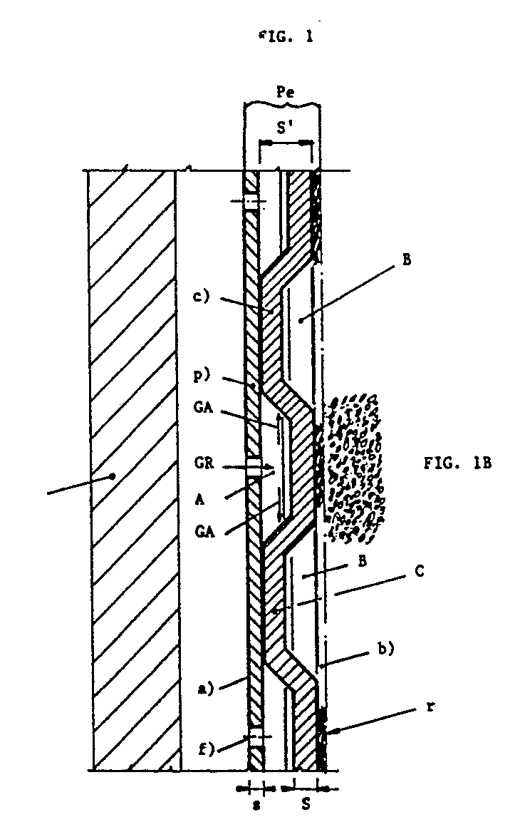
- Figure 1 is the view of a longitudinal cross-section of a portion of wall Pe of a reactor (as shown on a small scale in Fig. 1C) consisting of shell (M) and of the catalyst-containing external wall (Pe), external wall (Pe) being formed by: 1) element a) for the distribution of gas consiting of a thin wall permeable to gas with the exclusive function of effecting the necessary pressure drop and with the limited function of mechanical support, the wall having a small thickness (s) and being provided with perforations (f); 2) element b) with the exclusive function of containing the catalyst consisting for example of net (r) permeable to gas with a mesh size smaller than the catalyst's minimum size and having no function as support of the catalytic bed; 3) element c) consisting of a thick wall (S) combining the function of mechanical support for the catalytic bed and of forming the necessary airspace with thickness (S′) between elements a) and b) to ensure the correct distribution of gas (elimination of direct impact
- Figure 1C shows a schematic view of a cartridge (CU) with 3 catalytic beds (CC1, CC2, CC3) where L is the length of a bed and D its diameter.
- the thickness (s) of part a) is 3 mm
- the thickness (S) of part b), consisting of a wall with "bridge” perforations is 6 mm
- the airspace between a) and b) (S′) is 11 mm, said airspace being divided into two zones: zone (A) situated in front of the gas (G) inlet perforation (f) which deviates the high-speed gas (G) flowing in a radial direction, giving it a substantially axial direction (GA) avoiding the direct impact with the catalyst, since the perforations (f) are situated in front of the depression in the bridge wall; said gas (GA) then feeds zone (B) of airspace (S′) or gas equalization chamber throughout the length of the catalytic bed.
Landscapes
- Chemical & Material Sciences (AREA)
- Organic Chemistry (AREA)
- Chemical Kinetics & Catalysis (AREA)
- Physics & Mathematics (AREA)
- Fluid Mechanics (AREA)
- Devices And Processes Conducted In The Presence Of Fluids And Solid Particles (AREA)
- Physical Or Chemical Processes And Apparatus (AREA)
- Hydrogen, Water And Hydrids (AREA)
Abstract
Description
- This invention is related to a system for the optimal distribution of gas in catalyst beds, the elimination of flow gradients, and the support with minimum bulk of the catalyst in reactors for heterogeneous synthesis and walls for reactor cartridges so obtained.
- It is well known how important it is to achieve the even distribution of gas throughout the catalyst in fixed-bed reactors for heterogeneous synthesis, such as for example the synthesis of ammonia, of methanol or other substances.
- The walls distributing the gas and containing the catalyst in the catalytic beds must furthermore provide, besides the proper distribution of the gas itself (even distribution for the entire length of the bed; minimum impact of the gas with the catalyst to avoid channeling and damaging the catalyst), the necessary mechanical support for the catalytic beds.
- It is well known, if effect, that the above-mentioned walls undergo considerable stress, both of a thermal and of a mechanical nature, owing to the settling of the catalyst and to thermal expansion as a result of the high temperatures used.
- As a result, the function of mechanical support, besides ensuring the even distribution of gas, is also of critical importance for the correct operation of the system.
- The optimal mechanical size of the various parts constituting the wall supporting the catalytic beds which must at the same time ensure the optimal distribution of gas is therefore one the critical aspects of the system.
- Another critical aspect is represented by the possibility of producing said walls in the smallest possible size or radial thickness in order to ensure a maximum volume available for the catalytic beds (maximum volume of the catalytic beds) with a minimum volume of expensive containers, or impact parts of the reactor, operating at high pressure.
- For this purpose said walls usually consist of several parts having different functions.
- As already described by the Applicants in European Patent No. 0265654 the walls containing the catalyst may consist of:
- a) a part permeable by gas (for example a perforated wall) for the purpose of effecting the pressure drop necessary to ensure the even distribution of gas throughout the bed;
- b) a part supporting the catalyst (for example net);
- c) an intermediate part situated between part a) and part b), for the purpose of creating an airspace to achieve a better distribution of the gas, such part consisting for example of a wall with "bridge" perforations.
- The above-mentioned airspace must fulfil the following functions:
- avoid the direct impact with the catalyst of the high speed gas coming from a), producing a pressure drop. To this end the radial flow of the gas leaving from the perforations in part a) must be deviated into an axial flow;
- equalize the flow of gas feeding the catalytic bed all along the bed itself. - Very complex solutions have been put forward for example in English Patents No. 1118750 and No. 1352550, in which the problems of gas distribution, of a reliable mechanical support for the catalyst in the catalytic beds, and of maximum use of the available volume of the containers in the catalyst-containing cartridges (minimum thickness or dimension of the walls) are not all solved at the same time in an optimal manner.
- In effect the known gas distribution walls described in the State of the Art generally combine in the same element the two functions (gas distribution and mechanical support) which very often have differing constructional requirements.
- When for example mechanical support is provided by using a thick wall which at the same time is used to distribute the gas by means of suitable perforations to ensure the necessary pressure drop, we are confronted with a non-optimal solution for the following reasons:
- 1 - perforation of thick walls is very expensive;
- 2 - a system is necessary in any case to create an airspace between the thick perforated wall and the catalyst support (net, for example);
- 3 - the overall dimensions (radial thickness) of the above-mentioned elements is considerable, taking away from the catalyst valuable space. It is essential, as already mentioned, to create the above walls capable of fulfilling all the required functions but with the smallest possible radial thickness.
- The Applicants have surprisingly found that the above problems can be solved with a system characterized by the fact that: 1) part a) is so thin as to be almost exclusively intended to produce the necessary pressure drop without contributing, unless to a small extent, if at all, to the mechanical support of the catalyst; 2) part b) is given openings smaller than the catalyst's minimum size, thus acting almost exclusively as catalyst container, without contributing to the mechanical support of the catalytic bed and with a low pressure drop; and 3) part c) is thicker than the other parts, so as to fulfil the double role of mechanical support for the catalytic bed and of forming the necessary airspace between a) and b) to achieve the optimal distribution of gas without a direct impact with the catalyst by the high speed gas and with the gas flow equalized for the total length of the bed.
- In a preferred embodiment of the invention part a) has a thickness (s) lower than 8 mm, preferably between 3 and 2 mm, and c) has a thickness (S) greater than 3 mm, preferably between 5 and 20 mm, thus creating an airspace with thickness (S′) of less than 45 mm, preferably between 8 and 16 mm; preferably part c) consists of a wall with "bridge" perforations forming the airspace with thickness (S′) said airspace being divided into two zones: zone (A) situated in front of gas (G) inlet perforation (f) for the purpose of deviating the high-speed gas (G) flowing radially into a substantially axial direction (GA) avoiding a direct impact with the catalyst, perforations (f) being situated in front of the depression in the bridge wall; said gas (GA) feeds therefore zone (B) of airspace (S′) or gas equalization chamber thus permitting the even distribution of the gas throughout the length of the catalytic bed.
- According to a particular aspect of the invention the walls of the catalytic beds with an L:D ratio of less than 3 consist substantially of elements b) and c).
- The invention includes the catalyst-containing cartridges whose walls are obtained according to the system in question.
- The purpose of the invention will become more apparent from the following description of the preferred but not limitative embodiment shown in the attached drawings.
- Figure 1A is the cross-section view of a reactor shown on a very small scale in Fig. 1, with shell (M) containing catalyst baskets CCi (Fig. 1C), consisting of an external gas distribution wall (Pe) and an internal wall (Pi).
- As mentioned above Figure 1 is the view of a longitudinal cross-section of a portion of wall Pe of a reactor (as shown on a small scale in Fig. 1C) consisting of shell (M) and of the catalyst-containing external wall (Pe), external wall (Pe) being formed by: 1) element a) for the distribution of gas consiting of a thin wall permeable to gas with the exclusive function of effecting the necessary pressure drop and with the limited function of mechanical support, the wall having a small thickness (s) and being provided with perforations (f); 2) element b) with the exclusive function of containing the catalyst consisting for example of net (r) permeable to gas with a mesh size smaller than the catalyst's minimum size and having no function as support of the catalytic bed; 3) element c) consisting of a thick wall (S) combining the function of mechanical support for the catalytic bed and of forming the necessary airspace with thickness (S′) between elements a) and b) to ensure the correct distribution of gas (elimination of direct impact with the catalyst and equalized flow throughout the bed).
- Figure 1C shows a schematic view of a cartridge (CU) with 3 catalytic beds (CC1, CC2, CC3) where L is the length of a bed and D its diameter.
- In a preferred but not limitative embodiment, and more particularly according to the example described above and shown in Fig. 1, the thickness (s) of part a) is 3 mm, the thickness (S) of part b), consisting of a wall with "bridge" perforations, is 6 mm and the airspace between a) and b) (S′) is 11 mm, said airspace being divided into two zones: zone (A) situated in front of the gas (G) inlet perforation (f) which deviates the high-speed gas (G) flowing in a radial direction, giving it a substantially axial direction (GA) avoiding the direct impact with the catalyst, since the perforations (f) are situated in front of the depression in the bridge wall; said gas (GA) then feeds zone (B) of airspace (S′) or gas equalization chamber throughout the length of the catalytic bed.
Claims (5)
Applications Claiming Priority (2)
| Application Number | Priority Date | Filing Date | Title |
|---|---|---|---|
| CH393488 | 1988-10-24 | ||
| CH3934/88 | 1988-10-24 |
Publications (2)
| Publication Number | Publication Date |
|---|---|
| EP0365929A2 true EP0365929A2 (en) | 1990-05-02 |
| EP0365929A3 EP0365929A3 (en) | 1990-07-04 |
Family
ID=4266639
Family Applications (1)
| Application Number | Title | Priority Date | Filing Date |
|---|---|---|---|
| EP89118951A Withdrawn EP0365929A3 (en) | 1988-10-24 | 1989-10-12 | System for the optimal gas distribution in reactors and walls thereof |
Country Status (4)
| Country | Link |
|---|---|
| EP (1) | EP0365929A3 (en) |
| JP (1) | JPH02160034A (en) |
| CN (1) | CN1042091A (en) |
| CA (1) | CA2001386C (en) |
Cited By (4)
| Publication number | Priority date | Publication date | Assignee | Title |
|---|---|---|---|---|
| EP0446592A1 (en) * | 1990-02-27 | 1991-09-18 | Ammonia Casale S.A. | A wall structure for the distribution of gas in catalytic beds and for the support with minimum dimensions of the catalyst in reactors for heterogeneous synthesis |
| EP1818094A1 (en) * | 2006-02-13 | 2007-08-15 | Ammonia Casale S.A. | Wall system for catalytic beds of synthesis reactors |
| EP3037165A1 (en) * | 2014-12-23 | 2016-06-29 | Casale SA | Method for realizing internal walls of catalytic reactors |
| EP4291325B1 (en) * | 2021-02-10 | 2024-11-27 | Casale Sa | Catalytic synthesis reactor |
Families Citing this family (1)
| Publication number | Priority date | Publication date | Assignee | Title |
|---|---|---|---|---|
| CN108854863B (en) * | 2017-05-11 | 2021-02-02 | 中国石化工程建设有限公司 | Particulate bed supporting structure and high-flux axial reactor |
Family Cites Families (2)
| Publication number | Priority date | Publication date | Assignee | Title |
|---|---|---|---|---|
| EP0062716B1 (en) * | 1981-04-15 | 1985-08-28 | Uop Inc. | Improved screen for collection and distribution of process streams and assembly of such screens |
| EP0265654A1 (en) * | 1986-09-25 | 1988-05-04 | Ammonia Casale S.A. | System and device to make catalytic basket walls for heterogeneous synthesis reactors |
-
1989
- 1989-10-12 EP EP89118951A patent/EP0365929A3/en not_active Withdrawn
- 1989-10-24 JP JP27509689A patent/JPH02160034A/en active Pending
- 1989-10-24 CA CA 2001386 patent/CA2001386C/en not_active Expired - Lifetime
- 1989-10-24 CN CN 89108137 patent/CN1042091A/en active Pending
Cited By (9)
| Publication number | Priority date | Publication date | Assignee | Title |
|---|---|---|---|---|
| EP0446592A1 (en) * | 1990-02-27 | 1991-09-18 | Ammonia Casale S.A. | A wall structure for the distribution of gas in catalytic beds and for the support with minimum dimensions of the catalyst in reactors for heterogeneous synthesis |
| EP1818094A1 (en) * | 2006-02-13 | 2007-08-15 | Ammonia Casale S.A. | Wall system for catalytic beds of synthesis reactors |
| WO2007093254A1 (en) * | 2006-02-13 | 2007-08-23 | Ammonia Casale S.A. | Wall system for catalytic beds of synthesis reactors |
| CN101384348B (en) * | 2006-02-13 | 2012-02-08 | 阿梅尼亚·卡萨莱股份有限公司 | Wall system for catalytic beds of synthesis reactors |
| US8158074B2 (en) | 2006-02-13 | 2012-04-17 | Ammonia Casale S.A. | Wall system for catalytic beds of synthesis reactors |
| EP3037165A1 (en) * | 2014-12-23 | 2016-06-29 | Casale SA | Method for realizing internal walls of catalytic reactors |
| WO2016102135A1 (en) * | 2014-12-23 | 2016-06-30 | Casale Sa | Method for realizing internal walls of catalytic reactors |
| US10155211B2 (en) | 2014-12-23 | 2018-12-18 | Casale Sa | Method for realizing internal walls of catalytic reactors |
| EP4291325B1 (en) * | 2021-02-10 | 2024-11-27 | Casale Sa | Catalytic synthesis reactor |
Also Published As
| Publication number | Publication date |
|---|---|
| CN1042091A (en) | 1990-05-16 |
| CA2001386A1 (en) | 1990-04-24 |
| CA2001386C (en) | 2001-05-29 |
| EP0365929A3 (en) | 1990-07-04 |
| JPH02160034A (en) | 1990-06-20 |
Similar Documents
| Publication | Publication Date | Title |
|---|---|---|
| EP1432507B1 (en) | Heterogeneous catalytic reactor with a modular catalytic cartridge | |
| EP1227878B1 (en) | Catalytic reactor | |
| RU1809778C (en) | Reactor | |
| AU766169B2 (en) | Improved scallop design for radial flow reactor internals | |
| EP3727668A1 (en) | Multi-bed catalytic converter | |
| ES8105580A1 (en) | Axial-radial reactor for heterogeneous synthesis | |
| BRPI0707912A2 (en) | wall system for catalytic synthesis reactor beds | |
| CA2001386C (en) | System for the optimal gas distribution in reactors and walls thereof | |
| MY128688A (en) | Production of vinyl acetate in a catalytic reactor equipped with filter and distribution bed | |
| US4357304A (en) | Moving catalyst bed reactor | |
| US4169879A (en) | Reactor suitable for chemical reactions bringing fluids into action in contact with a bed of solids | |
| EP0332757A2 (en) | Converters for heterogeneous catalytic synthesis, particularly for ammonia and methanol, under pressure | |
| EP0237888B1 (en) | Process to obtain an optimal gas distribution in catalytic beds for heterogeneous reactions in gaseous phase | |
| CA1243473A (en) | Device for achieving a uniform distribution of the gas flowing radially through a catalyst bed | |
| RU2067494C1 (en) | Device for distribution of gas and holding of catalyst in catalytic layers of radial and axial-radial reactors | |
| US2276340A (en) | Catalytic reactor | |
| US7718146B2 (en) | Enhanced bed separation in a styrene monomer reactor using milled plates | |
| EP0285887A2 (en) | System to obtain an optimal gas distribution in catalytic beds for heterogeneous reactions in gasseous phases | |
| EP0602288B1 (en) | Moving catalyst bed reactor | |
| JPH0521023B2 (en) | ||
| JPS6265903A (en) | Reactor for decomposing methanol | |
| JPH0150452B2 (en) | ||
| CN113613773A (en) | Method for retrofitting a catalytic converter | |
| WO2025199026A1 (en) | Optimized reactor centerpipe | |
| GB2634125A (en) | Tubular reactor with fixed bed |
Legal Events
| Date | Code | Title | Description |
|---|---|---|---|
| PUAI | Public reference made under article 153(3) epc to a published international application that has entered the european phase |
Free format text: ORIGINAL CODE: 0009012 |
|
| AK | Designated contracting states |
Kind code of ref document: A2 Designated state(s): AT DE ES FR GB GR IT NL |
|
| PUAL | Search report despatched |
Free format text: ORIGINAL CODE: 0009013 |
|
| AK | Designated contracting states |
Kind code of ref document: A3 Designated state(s): AT DE ES FR GB GR IT NL |
|
| 17P | Request for examination filed |
Effective date: 19900924 |
|
| 17Q | First examination report despatched |
Effective date: 19910128 |
|
| STAA | Information on the status of an ep patent application or granted ep patent |
Free format text: STATUS: THE APPLICATION IS DEEMED TO BE WITHDRAWN |
|
| 18D | Application deemed to be withdrawn |
Effective date: 19910608 |