EP0364329B1 - Dispositif de ventilation destiné à des incubateurs - Google Patents
Dispositif de ventilation destiné à des incubateurs Download PDFInfo
- Publication number
- EP0364329B1 EP0364329B1 EP89402706A EP89402706A EP0364329B1 EP 0364329 B1 EP0364329 B1 EP 0364329B1 EP 89402706 A EP89402706 A EP 89402706A EP 89402706 A EP89402706 A EP 89402706A EP 0364329 B1 EP0364329 B1 EP 0364329B1
- Authority
- EP
- European Patent Office
- Prior art keywords
- support
- incubator
- rotation
- shaft
- incubators
- Prior art date
- Legal status (The legal status is an assumption and is not a legal conclusion. Google has not performed a legal analysis and makes no representation as to the accuracy of the status listed.)
- Expired - Lifetime
Links
- 238000009423 ventilation Methods 0.000 claims description 13
- 238000006073 displacement reaction Methods 0.000 claims 1
- 238000005259 measurement Methods 0.000 claims 1
- 235000013601 eggs Nutrition 0.000 description 6
- 241000286209 Phasianidae Species 0.000 description 4
- 238000009374 poultry farming Methods 0.000 description 4
- 230000012447 hatching Effects 0.000 description 3
- 238000011534 incubation Methods 0.000 description 3
- 241000272517 Anseriformes Species 0.000 description 2
- 241000272201 Columbiformes Species 0.000 description 1
- 241000287828 Gallus gallus Species 0.000 description 1
- 241001465754 Metazoa Species 0.000 description 1
- 241000272458 Numididae Species 0.000 description 1
- 238000009395 breeding Methods 0.000 description 1
- 230000001488 breeding effect Effects 0.000 description 1
- 235000013330 chicken meat Nutrition 0.000 description 1
- 238000001816 cooling Methods 0.000 description 1
- 230000018109 developmental process Effects 0.000 description 1
- 238000010586 diagram Methods 0.000 description 1
- 238000010438 heat treatment Methods 0.000 description 1
- 238000004519 manufacturing process Methods 0.000 description 1
- 230000008520 organization Effects 0.000 description 1
- 244000144977 poultry Species 0.000 description 1
- 235000013594 poultry meat Nutrition 0.000 description 1
- 238000005096 rolling process Methods 0.000 description 1
- 238000003756 stirring Methods 0.000 description 1
- 230000002459 sustained effect Effects 0.000 description 1
Images

Classifications
-
- F—MECHANICAL ENGINEERING; LIGHTING; HEATING; WEAPONS; BLASTING
- F04—POSITIVE - DISPLACEMENT MACHINES FOR LIQUIDS; PUMPS FOR LIQUIDS OR ELASTIC FLUIDS
- F04D—NON-POSITIVE-DISPLACEMENT PUMPS
- F04D25/00—Pumping installations or systems
- F04D25/02—Units comprising pumps and their driving means
- F04D25/08—Units comprising pumps and their driving means the working fluid being air, e.g. for ventilation
- F04D25/12—Units comprising pumps and their driving means the working fluid being air, e.g. for ventilation the unit being adapted for mounting in apertures
-
- A—HUMAN NECESSITIES
- A01—AGRICULTURE; FORESTRY; ANIMAL HUSBANDRY; HUNTING; TRAPPING; FISHING
- A01K—ANIMAL HUSBANDRY; AVICULTURE; APICULTURE; PISCICULTURE; FISHING; REARING OR BREEDING ANIMALS, NOT OTHERWISE PROVIDED FOR; NEW BREEDS OF ANIMALS
- A01K41/00—Incubators for poultry
Definitions
- the present invention relates to a ventilation device intended for incubators and hatchers, that is to say small, medium and large artificial incubators intended to contain large quantities of eggs, generally of the order of 100 to 200,000 eggs, and within which the most homogeneous temperature and humidity conditions are maintained.
- the poultry profession now includes several independent branches among which we can note the hatcheries who, by means of artificial incubation in incubators of the type mentioned above, transform hatching eggs from selection and multiplication farms into chicks.
- these incubators consist of enclosures in which the eggs are placed on shelves, which are themselves placed on trolleys. In the case of chickens, the incubation lasts 21 days.
- Another problem encountered by hatcheries is related to the need to maintain a temperature in the internal part of the incubators that is as uniform as possible, in order to avoid any time lag in the time of hatching of the chicks; it has indeed been observed that a temperature difference of 1/10 of a degree between two points of an incubator causes after 21 days, a delay of the order of 6 hours in the hatching of the chicks.
- the ventilation systems conventionally used consist of large propellers mounted at the middle part of the incubator and rotating at a different speed depending on the model: this movement can be either printed directly on the shaft of the propeller, either be transmitted via toothed belts or pulleys; in all cases, these devices correspond to air agitators which are centrifugal at the end of the blades, that is to say located at the periphery of the incubator to bring it back to the central zone.
- the air is also less stirred in the center of the incubator than at its periphery and, as a result, the central part is significantly warmer.
- the object of the present invention is to remedy the aforementioned drawbacks by proposing a ventilation device such as to create a uniform stirring of the air over the entire volume of the incubator and, consequently, to eliminate any difference in temperature at inside this volume.
- This device which comprises a support is centrifugal and comprises a main shaft provided with blades capable of moving, by rotation around itself, characterized in that the shaft is supported for rotation around its center in a plane comprising the axis of said tree.
- FR-A-2 144 285 discloses a ventilation device with the characteristics of the preamble of claim 1.
- the device comprises a circular crown cooperating with a drive pulley whose rotation is controlled by a motor and carrying two diametrically opposed rings provided with bearings, in particular ball bearings and acting as a bearing for the main tree.
- the above-mentioned double movement therefore corresponds, on the one hand, to the rotation of the main shaft in its bearings and, on the other hand, to the rotation of the circular crown.
- the device comprises a flat support provided, in its central part, with a circular orifice the periphery of which acts, on one of its faces or first face, as a raceway for a roller mounted at one end of the main shaft.
- the drive pulley cooperates with auxiliary pulleys mounted idly to guide and maintain the circular crown on the second face of the support opposite the first, parallel to the latter.
- the diameter of the circular crown corresponds approximately to that of the orifice of the planar support.
- a screw for adjusting the force of application of the roller on its raceway.
- the incubators are most often in the form of cubes; in this case, it is particularly advantageous to provide a support of square shape of the same dimension as the sides of the incubator and to mount this support vertically according to one of the median planes of the incubator.
- a cubic incubator 1 shown in dotted lines is provided, in its middle part, with a planar support 2 carrying ventilation elements which will be described in more detail in the remainder of this description.
- the incubator 1 is intended to receive eggs placed on shelves not shown.
- the support 2 is arranged vertically and has a square shape whose dimensions correspond to those of one side of the cube 1.
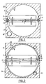
- the support 2 shown in hatched is provided at its central part with a circular orifice 3 of large diameter; the latter is in fact chosen so as to be maximum while by providing sufficient rigidity at the edges of the support.
- a main shaft 4 carrying blades 5 is mounted on the support 2, along a diameter x-x ′ of the orifice 3 in a manner which will be described in more detail below.
- the figures represent the particular case of a main shaft 4 provided with two, three or four blades 5; this number is, of course, in no way limit the invention.
- the main shaft 4 is capable of moving simultaneously according to two different rotational movements; the first of these movements corresponds to a rotation on itself around its axis xx ′ according to arrow I, while the second of these movements corresponds to a rotation according to arrow II around its center C which corresponds to the center of l orifice 3 in a plane coinciding with that of support 2.
- the main shaft 4 carries at one of its ends a roller 6 capable of rolling on a first face 20 of the support 2, at the periphery of the orifice 3; this movement causes the main shaft 4 to rotate about itself about its axis x-x ′.
- a circular crown 7 whose diameter corresponds approximately to that of the orifice 3 of the support 2 and which coincides with this orifice is mounted on the second face 21 of the support 2, while being maintained, on the one hand, by three additional pulleys 8 mounted idly on the support 2, and on the other hand, by a driving pulley 9 driven in rotation by a motor 10 shown in Figure 2. It is clear that the rotation along arrow III of the driving pulley 9 drives the rotation according to arrow II of the circular crown 7.
- the circular crown 7 is integral with two diametrically opposite bearing rings 11, 11 ′ which act as bearings for the main shaft 4, which is also automatically driven according to arrow II as a result of the movement of the circular crown 7. It is thus clear that the only motor 10 makes it possible to control the rotation of the ventilation system according to movements I and II.
- a screw 12 also makes it possible to adjust the force of application of the roller 6 on its raceway which is formed by the periphery of the orifice 3 on the first face 20 of the support 2.
Landscapes
- Environmental Sciences (AREA)
- Life Sciences & Earth Sciences (AREA)
- Engineering & Computer Science (AREA)
- General Engineering & Computer Science (AREA)
- Biodiversity & Conservation Biology (AREA)
- Mechanical Engineering (AREA)
- Animal Husbandry (AREA)
- Accommodation For Nursing Or Treatment Tables (AREA)
- Catching Or Destruction (AREA)
- Input Circuits Of Receivers And Coupling Of Receivers And Audio Equipment (AREA)
- Structure Of Receivers (AREA)
- Transmitters (AREA)
- Air-Conditioning For Vehicles (AREA)
- Packaging Of Machine Parts And Wound Products (AREA)
- Specific Sealing Or Ventilating Devices For Doors And Windows (AREA)
Description
- La présente invention concerne un dispositif de ventilation destiné à des incubateurs et éclosoirs, c'est-à-dire des couveuses artificielles de petite, moyenne et grande dimension destinées à contenir des grandes quantités d'oeufs, généralement de l'ordre de 100 à 200 000 oeufs, et à l'intérieur desquelles sont maintenues des conditions de température et d'humidité les plus homogènes possibles.
- Depuis les cinquante dernières années, l'aviculture utilitaire, c'est-à-dire l'élevage des gallinacés (poules, pintades, dindes, cailles, faisans, perdrix ...) mais aussi de colombidés tels que des pigeons et de palmipèdes, notamment de canards et d'oies, a connu un développement très rapide et une industrialisation qui a apporté de nombreuses modifications à l'organisation des productions. En conséquence, l'aviculture traditionnelle ou aviculture fermière est le plus souvent remplacée par une aviculture rationnelle qui se distingue avant tout par sa concentration, sa mécanisation et sa spécialisation.
- Ainsi, la profession avicole comprend maintenant plusieurs branches indépendantes parmi lesquelles on peut noter les accouveurs qui, par le moyen de l'incubation artificielle dans des incubateurs du type susmentionné, transforment en poussins les oeufs à couver provenant des élevages de sélection et de multiplication.
- De manière classique, ces incubateurs sont constitués par des enceintes dans lesquelles les oeufs sont disposés sur des clayettes, elles-mêmes disposées sur des chariots. Dans le cas des poules, l'incubation dure 21 jours.
- Les principaux problèmes rencontrés par les accouveurs sont liés à la nécessité d'obtenir, dans les incubateurs, une température la plus uniforme possible ; cette température est, en effet, relativement difficile à maintenir étant donné qu'en début d'incubation, il est nécessaire de prévoir un chauffage, alors qu'au bout de quelques jours chaque oeuf dégage une énergie de l'ordre de 1/10 de watt, ce qui oblige à prévoir un refroidissement.
- Un autre problème auquel se heurtent les accouveurs est est lié à la nécessité de maintenir à la partie interne des incubateurs une température qui soit aussi uniforme que possible, afin d'éviter tout décalage dans le temps de l'instant d'éclosion des poussins ; on a en effet pu constater qu'une différence de température de 1/10 de degré entre deux points d'un incubateur entraîne au bout de 21 jours, un décalage de l'ordre de 6 heures de l'éclosion des poussins.
- Pour remédier aux problèmes susmentionnés, il est nécessaire de munir la partie interne de l'incubateur, d'un système de ventilation.
- Les systèmes de ventilation classiquement utilisé sont constitués par de grandes hélices montées à la partie médiane de l'incubateur et tournant à une vitesse différente selon les modèles : ce mouvement peut être soit imprimé directement à l'arbre de l'hélice, soit être transmis par l'intermédiaire de courroies crantées ou de poulies ; dans tous les cas, ces dispositifs correspondent à des agitateurs d'air qui sont centrifuges en bout de pales, c'est-à-dire situées à la périphérie de l'incubateur pour le ramener dans la zone centrale.
- Avec de tels dispositifs, l'air est en outre moins remué au centre de l'incubateur qu'à sa périphérie et, il en résulte que la partie centrale est nettement plus chaude.
- Pour résoudre ce problème et trouver un système de ventilation permettant d'obtenir un brassage soutenu au centre de l'incubateur qu'à sa périphérie, on a tenté d'agir sur la forme des pales, mais, on n'a pas pu ainsi obtenir de résultats satisfaisants compte tenu du fait que la vitesse linéaire du dispositif est toujours plus élevée en bout de pales et que l'air revient toujours vers le centre, d'où il résulte un point chaud dans la partie centrale de l'incubateur.
- La présente invention a pour objet de remédier aux inconvénients susmentionnés en proposant un dispositif de ventilation de nature à créer un brassage uniforme de l'air sur la totalité du volume de l'incubateur et, par suite, d'éliminer toute différence de température à l'intérieur de ce volume.
- Ce dispositif qui comprend un support est centrifuge et comporte un arbre principal muni de pales susceptible de se déplacer, par rotation autour de lui-même, caractérisé en ce que l'arbre est supporté pour rotation autour de son centre dans un plan comportant l'axe dudit arbre. FR-A-2 144 285 révèle un dispositif de ventilation avec les caractéristiques du préambule de la revendication 1.
- Ce double mouvement de l'arbre et des pales permet de ventiler en permanence la partie centrale de l'incubateur étant donné que l'air ne peut pas revenir au centre.
- Suivant une autre caractéristique de l'invention, le dispositif comporte une couronne circulaire coopérant avec une poulie motrice dont la rotation est commandée par un moteur et portant deux bagues diamétralement opposées munies de roulements, notamment de roulements à billes et faisant office de palier pour l'arbre principal.
- La double mouvement susmentionné correspond donc, d'une part, à la rotation de l'arbre principal dans ses paliers et, d'autre part, à la rotation de la couronne circulaire.
- Suivant une autre caractéristique de l'invention, le dispositif comporte un support plan muni, en sa partie centrale, d'un orifice circulaire dont la périphérie fait office, sur l'une de ses faces ou première face, de chemin de roulement pour un galet monté à l'une des extrémités de l'arbre principal.
- Par suite de cette configuration, la rotation de la couronne circulaire entraîne automatiquement la rotation autour de son axe de l'arbre principal, ce qui signifie que le double mouvement susmentionné est commandé par un même moteur.
- Suivant une autre caractéristique de l'invention, la poulie motrice coopère avec des poulies annexes montées folles pour guider et maintenir la couronne circulaire sur la seconde face du support opposée à la première, parallèlement à celle-ci.
- Suivant une autre caractéristique de l'invention, le diamètre de la couronne circulaire correspond approximativement à celui de l'orifice du support plan.
- Bien entendu, ces deux éléments doivent être montés concentriques.
- Suivant une autre caractéristique de l'invention, il est prévu une vis de réglage de la force d'application du galet sur son chemin de roulement.
- Bien qu'il ne s'agisse pas là d'une caractéristique limitative de l'invention, les incubateurs sont le plus souvent en forme de cubes ; dans ce cas, il est particulièrement avantageux de prévoir un support de forme carrée de même dimension que les côtés de l'incubateur et de monter ce support verticalement selon l'un des plans médians de l'incubateur.
- De plus, pour obtenir une ventilation optimale, il est nécessaire que les pales soient aussi longues que possible, et donc, par suite que le diamètre de l'orifice du support plan soit maximum.
- Les caractéristiques du dispositif de ventilation destiné à des incubateurs qui fait l'objet de l'invention seront décrites plus en détail conformément aux dessins annexés dans lesquels :
- la figure 1 est un schéma représentant le ventilateur mis en place dans un incubateur cubique,
- les figures 2 et 3 représentent, respectivement, les première et seconde faces du support.
- Selon la figure 1, un incubateur cubique 1 représenté en pointillés est muni, en sa partie médiane, d'un support plan 2 portant des éléments de ventilation qui seront décrits plus en détail dans la suite de cet exposé.
- L'incubateur 1 est destiné à recevoir des oeufs disposés sur des clayettes non représentées.
- Le support 2 est disposé verticalement et a une forme carrée dont les dimensions correspondent à celles d'un côté du cube 1.
- Selon les figures 2 et 3, le support 2, représenté en hachurés, est muni à sa partie centrale d'un orifice circulaire 3 de grand diamètre ; ce dernier est en fait choisi de manière à être maximum tout en conférant une rigidité suffisante au niveau des bords du support.
- Selon la figure 2, un arbre principal 4 portant des pales 5 est monté sur le support 2, le long d'un diamètre x-x′ de l'orifice 3 d'une façon qui sera décrite plus en détail ci-dessous. Dans un but de simplification, les figures représentent le cas particulier d'un arbre principal 4 muni de deux, trois ou quatre pales 5 ; ce nombre n'est, bien entendu, nullement limitatif de l'invention.
- L'arbre principal 4 est susceptible de se déplacer simultanément selon deux mouvements de rotation différents ; le premier de ces mouvements correspond à une rotation sur lui-même autour de son axe x-x′ selon la flèche I, tandis que le second de ces mouvements correspond à une rotation selon la flèche II autour de son centre C qui correspond au centre de l'orifice 3 dans un plan coïncidant avec celui du support 2.
- Selon la figure 2, l'arbre principal 4 porte à l'une de ses extrémités un galet 6 susceptible de rouler sur une première face 20 du support 2, à la périphérie de l'orifice 3 ; ce mouvement entraîne la rotation sur lui-même de l'arbre principal 4 autour de son axe x-x′.
- Selon la figure 3, une couronne circulaire 7 dont le diamètre correspond approximativement à celui de l'orifice 3 du support 2 et qui coïncide avec cet orifice est montée sur la seconde face 21 du support 2, en étant maintenue, d'une part, par trois poulies annexes 8 montées folles sur le support 2, et d'autre part, par une poulie motrice 9 entraînée en rotation par un moteur 10 représenté sur la figure 2. Il est clair que la rotation selon la flèche III de la poulie motrice 9 entraîne la rotation selon la flèche II de la couronne circulaire 7.
- Par ailleurs, selon la figure 3, la couronne circulaire 7 est solidaire de deux bagues à roulements diamétralement opposée 11, 11′ qui font office de paliers pour l'arbre principal 4, qui se trouve également entraîné automatiquement selon la flèche II par suite du mouvement de la couronne circulaire 7. Il est ainsi clair que le seul moteur 10 permet de commander la rotation du système de ventilation selon les mouvements I et II.
- Comme représenté schématiquement sur la figure 3, une vis 12 permet en outre de régler la force d'application du galet 6 sur son chemin de roulement qui est constitué par la périphérie de l'orifice 3 sur la première face 20 du support 2.
- Comme il a déjà été indiqué ci-dessus, ce double mouvement du système de ventilation permet d'obtenir une ventilation uniforme de l'ensemble de l'incubateur 1 étant donné que l'air, ventilé en permanence, ne peut pas venir en sa partie centrale.
Claims (10)
- Dispositif de ventilation destiné à des incubateurs et éclosoirs, comprenant un support (2) lequel dispositif est centrifuge et comporte un arbre principal (4) muni de pales (5) susceptible de se déplacer, par rotation autour de lui-même, caractérisé en ce que l'arbre est supporté pour rotation autour de son centre (C) dans un plan comportant l'axe dudit arbre.
- Dispositif selon la revendication 1, caractérisé en ce qu'il comporte une couronne circulaire (7) coopérant avec une poulie motrice (9) dont la rotation est commandée par un moteur (10) et portant deux bagues (11, 111′) diamétralement opposées munies de roulement, notamment de roulement à billes et faisant office de palier pour l'arbre principal (4).
- Dispositif selon l'une quelconque des revendications 1 et 2, caractérisé en ce qu'il comporte un support plan (2) muni, en sa partie centrale, d'un orifice circulaire (3) dont la périphérie fait office, sur l'une de ses faces (20) ou première face, de chemin de roulement pour un galet (6) monté à lune des extrémités de l'arbre principal (4).
- Dispositif selon l'une quelconque des revendications à à 3, caractérisé en ce que la poulie motrice (9) coopère avec des poulies annexes (8) montées folles pour guider et maintenir la couronne circulaire (7) sur la seconde face (21) du support (2) opposée à la première (20), parallèlement à celle-ci.
- Dispositif selon l'une quelconque des revendications 1 à 4, caractérisé en ce que le diamètre de la couronne circulaire (7) correspond approximativement à celui de l'orifice (3) du support plan (2).
- Dispositif selon l'une quelconque des revendications 1 à 5, caractérisé en ce qu'il comporte une vis de réglage (12) de la force d'application du galet (6) sur son chemin de roulement.
- Dispositif selon l'une quelconque des revendications 1 à 6, caractérisé en ce que le support (2) est disposé verticalement à la partie médiane de l'incubateur (1).
- Dispositif selon l'une quelconque des revendications 1 à 7, caractérisé en ce que le support (2) a une forme qui coopère avec celle de l'incubateur (1).
- Dispositif selon la revendication 8, caractérisé en ce que le support (2) est de même dimension que les côtés de l'incubateur (1).
- Dispositif selon la revendication 9, caractérisé en ce que le diamètre de l'orifice (3) du support plan (2) est maximum.
Priority Applications (1)
| Application Number | Priority Date | Filing Date | Title |
|---|---|---|---|
| AT89402706T ATE86065T1 (de) | 1988-10-10 | 1989-10-02 | Belueftungsvorrichtung fuer brutmaschinen. |
Applications Claiming Priority (2)
| Application Number | Priority Date | Filing Date | Title |
|---|---|---|---|
| FR8813277 | 1988-10-10 | ||
| FR8813277A FR2637456B1 (fr) | 1988-10-10 | 1988-10-10 | Dispositif de ventilation destine a des incubateurs |
Publications (2)
| Publication Number | Publication Date |
|---|---|
| EP0364329A1 EP0364329A1 (fr) | 1990-04-18 |
| EP0364329B1 true EP0364329B1 (fr) | 1993-03-03 |
Family
ID=9370850
Family Applications (1)
| Application Number | Title | Priority Date | Filing Date |
|---|---|---|---|
| EP89402706A Expired - Lifetime EP0364329B1 (fr) | 1988-10-10 | 1989-10-02 | Dispositif de ventilation destiné à des incubateurs |
Country Status (4)
| Country | Link |
|---|---|
| EP (1) | EP0364329B1 (fr) |
| AT (1) | ATE86065T1 (fr) |
| DE (1) | DE68905130D1 (fr) |
| FR (1) | FR2637456B1 (fr) |
Families Citing this family (2)
| Publication number | Priority date | Publication date | Assignee | Title |
|---|---|---|---|---|
| CN104165151B (zh) * | 2014-06-30 | 2016-03-23 | 张家港市海鑫五金制品有限公司 | 一种安全型排风扇 |
| CN111502039A (zh) * | 2020-05-14 | 2020-08-07 | 永州职业技术学院 | 一种建筑工程用防水结构 |
Family Cites Families (4)
| Publication number | Priority date | Publication date | Assignee | Title |
|---|---|---|---|---|
| US1721249A (en) * | 1928-04-27 | 1929-07-16 | Diehl Mfg Co | Gyratory fan |
| US2213873A (en) * | 1938-03-25 | 1940-09-03 | Henry E Van Derschaegh | Revolving fan |
| FR1545536A (fr) * | 1966-12-02 | 1968-11-08 | Séchoir, notamment pour le séchage de bois de sciage | |
| CH541077A (de) * | 1971-06-26 | 1973-08-31 | Siemens Ag | Lüfteraggregat |
-
1988
- 1988-10-10 FR FR8813277A patent/FR2637456B1/fr not_active Expired - Fee Related
-
1989
- 1989-10-02 AT AT89402706T patent/ATE86065T1/de not_active IP Right Cessation
- 1989-10-02 EP EP89402706A patent/EP0364329B1/fr not_active Expired - Lifetime
- 1989-10-02 DE DE8989402706T patent/DE68905130D1/de not_active Expired - Lifetime
Also Published As
| Publication number | Publication date |
|---|---|
| ATE86065T1 (de) | 1993-03-15 |
| FR2637456A1 (fr) | 1990-04-13 |
| EP0364329A1 (fr) | 1990-04-18 |
| DE68905130D1 (de) | 1993-04-08 |
| FR2637456B1 (fr) | 1992-12-11 |
Similar Documents
| Publication | Publication Date | Title |
|---|---|---|
| FR2607776A1 (fr) | Objet volant pour collecter les rayons solaires | |
| EP2212197B1 (fr) | Engin volant a deux rotors | |
| EP0364329A1 (fr) | Dispositif de ventilation destiné à des incubateurs | |
| CH662407A5 (fr) | Procede et dispositif pour le rechauffement d'aliments par micro-ondes. | |
| CA3129980A1 (fr) | Dispositif de propulsion pour aerodyne a voilure tournante et a decollage et atterrissage verticaux, et aerodyne comprenant au moins un tel dispositif de propulsion | |
| CN114847064B (zh) | 一种夜蛾黑卵蜂田间放蜂定位系统 | |
| WO2018231370A1 (fr) | Systèmes et procédés de programmation d'un module de culture | |
| US4020565A (en) | Draft inducing roof for storage structures | |
| FR2654410A1 (fr) | Fente actionnee mecaniquement pour rotor a commande de circulation notamment pour un aeronef a voilure en x. | |
| WO2018109151A1 (fr) | Systeme de production d'energie electrique a l'interieur d'une serre | |
| US11470789B2 (en) | System for providing controlled environment to grow plants and apparatus therefor | |
| FR2417249A1 (fr) | Dispositif de fauchage | |
| CN212274463U (zh) | 一种基于光线反射的饲料生产用晾晒盘 | |
| RU2034448C1 (ru) | Теплица | |
| CN108344270A (zh) | 一种曲柄滑块控制食品快速风干装置 | |
| FR3074648A1 (fr) | Machine a egrapper le raisin encore appelee egrappoir | |
| FR2474604A1 (fr) | Aero-generateur a roue a ailettes et induits peripheriques | |
| FR2495891A1 (fr) | Procede et dispositifs de culture rotative | |
| FR2622083A1 (fr) | Groupe de ventilation pour une enceinte d'incubation d'oeufs ou une enceinte d'eclosoir | |
| CN211746242U (zh) | 一种供科普用小型孵化器 | |
| RU2028779C1 (ru) | Инкубатор | |
| CN223262192U (zh) | 一种草莓种植用鸟类驱赶装置 | |
| FR2556927A1 (fr) | Dispositif pour la germination et la culture de plantes d'appartement | |
| FR2787290A1 (fr) | Dispositif de maintien en temperature hors gel d'une surface cultivee, notamment une parcelle de vigne | |
| CN112450128B (zh) | 一种胚胎蛋孵化速度的控制方法 |
Legal Events
| Date | Code | Title | Description |
|---|---|---|---|
| PUAI | Public reference made under article 153(3) epc to a published international application that has entered the european phase |
Free format text: ORIGINAL CODE: 0009012 |
|
| AK | Designated contracting states |
Kind code of ref document: A1 Designated state(s): AT BE CH DE ES GB GR IT LI LU NL SE |
|
| 17P | Request for examination filed |
Effective date: 19900518 |
|
| 17Q | First examination report despatched |
Effective date: 19911023 |
|
| GRAA | (expected) grant |
Free format text: ORIGINAL CODE: 0009210 |
|
| AK | Designated contracting states |
Kind code of ref document: B1 Designated state(s): AT BE CH DE ES GB GR IT LI LU NL SE |
|
| PG25 | Lapsed in a contracting state [announced via postgrant information from national office to epo] |
Ref country code: IT Free format text: LAPSE BECAUSE OF FAILURE TO SUBMIT A TRANSLATION OF THE DESCRIPTION OR TO PAY THE FEE WITHIN THE PRE;WARNING: LAPSES OF ITALIAN PATENTS WITH EFFECTIVE DATE BEFORE 2007 MAY HAVE OCCURRED AT ANY TIME BEFORE 2007. THE CORRECT EFFECTIVE DATE MAY BE DIFFERENT FROM THE ONE RECORDED.SCRIBED TIME-LIMIT Effective date: 19930303 Ref country code: AT Effective date: 19930303 Ref country code: GB Effective date: 19930303 Ref country code: SE Effective date: 19930303 Ref country code: ES Free format text: THE PATENT HAS BEEN ANNULLED BY A DECISION OF A NATIONAL AUTHORITY Effective date: 19930303 Ref country code: DE Effective date: 19930303 Ref country code: NL Effective date: 19930303 Ref country code: GR Free format text: LAPSE BECAUSE OF FAILURE TO SUBMIT A TRANSLATION OF THE DESCRIPTION OR TO PAY THE FEE WITHIN THE PRESCRIBED TIME-LIMIT Effective date: 19930303 |
|
| REF | Corresponds to: |
Ref document number: 86065 Country of ref document: AT Date of ref document: 19930315 Kind code of ref document: T |
|
| REF | Corresponds to: |
Ref document number: 68905130 Country of ref document: DE Date of ref document: 19930408 |
|
| NLV1 | Nl: lapsed or annulled due to failure to fulfill the requirements of art. 29p and 29m of the patents act | ||
| GBV | Gb: ep patent (uk) treated as always having been void in accordance with gb section 77(7)/1977 [no translation filed] |
Effective date: 19930303 |
|
| PG25 | Lapsed in a contracting state [announced via postgrant information from national office to epo] |
Ref country code: LI Effective date: 19931031 Ref country code: LU Free format text: LAPSE BECAUSE OF NON-PAYMENT OF DUE FEES Effective date: 19931031 Ref country code: BE Effective date: 19931031 Ref country code: CH Effective date: 19931031 |
|
| PLBE | No opposition filed within time limit |
Free format text: ORIGINAL CODE: 0009261 |
|
| STAA | Information on the status of an ep patent application or granted ep patent |
Free format text: STATUS: NO OPPOSITION FILED WITHIN TIME LIMIT |
|
| 26N | No opposition filed | ||
| BERE | Be: lapsed |
Owner name: GOURDON JEAN Effective date: 19931031 Owner name: S.A. LA NATIONALE Effective date: 19931031 |
|
| REG | Reference to a national code |
Ref country code: CH Ref legal event code: PL Ref country code: CH Ref legal event code: AUV Free format text: LE BREVET CI DESSUS EST TOMBE EN DECHEANCE FAUTE DE PAIEMENT, DE LA 5E ANNUITE. |