EP0363648B1 - Verfahren und Vorrichtung zur Herstellung oder Modifikation von Schneidkanten - Google Patents
Verfahren und Vorrichtung zur Herstellung oder Modifikation von Schneidkanten Download PDFInfo
- Publication number
- EP0363648B1 EP0363648B1 EP89116550A EP89116550A EP0363648B1 EP 0363648 B1 EP0363648 B1 EP 0363648B1 EP 89116550 A EP89116550 A EP 89116550A EP 89116550 A EP89116550 A EP 89116550A EP 0363648 B1 EP0363648 B1 EP 0363648B1
- Authority
- EP
- European Patent Office
- Prior art keywords
- ion
- blades
- stack
- cutting edges
- bombardment
- Prior art date
- Legal status (The legal status is an assumption and is not a legal conclusion. Google has not performed a legal analysis and makes no representation as to the accuracy of the status listed.)
- Expired - Lifetime
Links
Images


Classifications
-
- C—CHEMISTRY; METALLURGY
- C23—COATING METALLIC MATERIAL; COATING MATERIAL WITH METALLIC MATERIAL; CHEMICAL SURFACE TREATMENT; DIFFUSION TREATMENT OF METALLIC MATERIAL; COATING BY VACUUM EVAPORATION, BY SPUTTERING, BY ION IMPLANTATION OR BY CHEMICAL VAPOUR DEPOSITION, IN GENERAL; INHIBITING CORROSION OF METALLIC MATERIAL OR INCRUSTATION IN GENERAL
- C23C—COATING METALLIC MATERIAL; COATING MATERIAL WITH METALLIC MATERIAL; SURFACE TREATMENT OF METALLIC MATERIAL BY DIFFUSION INTO THE SURFACE, BY CHEMICAL CONVERSION OR SUBSTITUTION; COATING BY VACUUM EVAPORATION, BY SPUTTERING, BY ION IMPLANTATION OR BY CHEMICAL VAPOUR DEPOSITION, IN GENERAL
- C23C14/00—Coating by vacuum evaporation, by sputtering or by ion implantation of the coating forming material
- C23C14/22—Coating by vacuum evaporation, by sputtering or by ion implantation of the coating forming material characterised by the process of coating
- C23C14/225—Oblique incidence of vaporised material on substrate
-
- C—CHEMISTRY; METALLURGY
- C23—COATING METALLIC MATERIAL; COATING MATERIAL WITH METALLIC MATERIAL; CHEMICAL SURFACE TREATMENT; DIFFUSION TREATMENT OF METALLIC MATERIAL; COATING BY VACUUM EVAPORATION, BY SPUTTERING, BY ION IMPLANTATION OR BY CHEMICAL VAPOUR DEPOSITION, IN GENERAL; INHIBITING CORROSION OF METALLIC MATERIAL OR INCRUSTATION IN GENERAL
- C23C—COATING METALLIC MATERIAL; COATING MATERIAL WITH METALLIC MATERIAL; SURFACE TREATMENT OF METALLIC MATERIAL BY DIFFUSION INTO THE SURFACE, BY CHEMICAL CONVERSION OR SUBSTITUTION; COATING BY VACUUM EVAPORATION, BY SPUTTERING, BY ION IMPLANTATION OR BY CHEMICAL VAPOUR DEPOSITION, IN GENERAL
- C23C14/00—Coating by vacuum evaporation, by sputtering or by ion implantation of the coating forming material
- C23C14/02—Pretreatment of the material to be coated
- C23C14/021—Cleaning or etching treatments
- C23C14/022—Cleaning or etching treatments by means of bombardment with energetic particles or radiation
-
- C—CHEMISTRY; METALLURGY
- C23—COATING METALLIC MATERIAL; COATING MATERIAL WITH METALLIC MATERIAL; CHEMICAL SURFACE TREATMENT; DIFFUSION TREATMENT OF METALLIC MATERIAL; COATING BY VACUUM EVAPORATION, BY SPUTTERING, BY ION IMPLANTATION OR BY CHEMICAL VAPOUR DEPOSITION, IN GENERAL; INHIBITING CORROSION OF METALLIC MATERIAL OR INCRUSTATION IN GENERAL
- C23C—COATING METALLIC MATERIAL; COATING MATERIAL WITH METALLIC MATERIAL; SURFACE TREATMENT OF METALLIC MATERIAL BY DIFFUSION INTO THE SURFACE, BY CHEMICAL CONVERSION OR SUBSTITUTION; COATING BY VACUUM EVAPORATION, BY SPUTTERING, BY ION IMPLANTATION OR BY CHEMICAL VAPOUR DEPOSITION, IN GENERAL
- C23C14/00—Coating by vacuum evaporation, by sputtering or by ion implantation of the coating forming material
- C23C14/22—Coating by vacuum evaporation, by sputtering or by ion implantation of the coating forming material characterised by the process of coating
-
- C—CHEMISTRY; METALLURGY
- C23—COATING METALLIC MATERIAL; COATING MATERIAL WITH METALLIC MATERIAL; CHEMICAL SURFACE TREATMENT; DIFFUSION TREATMENT OF METALLIC MATERIAL; COATING BY VACUUM EVAPORATION, BY SPUTTERING, BY ION IMPLANTATION OR BY CHEMICAL VAPOUR DEPOSITION, IN GENERAL; INHIBITING CORROSION OF METALLIC MATERIAL OR INCRUSTATION IN GENERAL
- C23F—NON-MECHANICAL REMOVAL OF METALLIC MATERIAL FROM SURFACE; INHIBITING CORROSION OF METALLIC MATERIAL OR INCRUSTATION IN GENERAL; MULTI-STEP PROCESSES FOR SURFACE TREATMENT OF METALLIC MATERIAL INVOLVING AT LEAST ONE PROCESS PROVIDED FOR IN CLASS C23 AND AT LEAST ONE PROCESS COVERED BY SUBCLASS C21D OR C22F OR CLASS C25
- C23F4/00—Processes for removing metallic material from surfaces, not provided for in group C23F1/00 or C23F3/00
Definitions
- This invention is concerned with a method and apparatus for forming or modifying cutting edges by ion bombardment to cause sputter removal of the material of the workpiece.
- the invention is particularly, but not exclusively, useful in forming very thin ("ultra fine") cutting edges for razor blades.
- the shaving performance of razor blades would be significantly improved if the thickness of the cutting edge over a distance back from the ultimate tip was substantially less than that of currently available razor blades.
- cutting edge is used in this specification to refer to the whole marginal zone of a razor blade which is bounded by tapering surfaces or, in everyday parlance, is sharpened, while “ultimate tip” is used to refer to the final edge or tip of the razor blade; in conventional razor blades, the cutting edge extends some 400-500 ⁇ m back from the ultimate tip).
- the minimum thickness of the cutting edge is determined by the yield or fracture strength of the blade material.
- a is the calculated thickness, i.e. tip width w, when d is 1 ⁇ m.
- the actual tip width or thickness at 1 ⁇ m should be more than 0.7 ⁇ m in order to minimise damage to the cutting edge during shaving, but less than 1.0 ⁇ m in order to obtain a comfortable shave.
- n is equally or more important than the value of a since it (n) determines the shape of the edge.
- a value of 0.5 defines a parabola, while a value of 1.0 defines a simple wedge.
- Previous cutting edges had n values of more than 0.75; the cutting edges defined in the British specification referred to above have n values of from 0.65 to 0.75.
- the above British specification also describes composite cutting edges, that is edges comprising a substrate cutting edge of stainless steel and a coating thereon of a material having a higher yield strength than stainless steel.
- the composite cutting edge cross-sectional shape should satisfy two equations w ⁇ 1 m ad n and w3 ⁇ (w-2h) a2d 2n where h is the thickness, in ⁇ m, of the coating at the distance d, in ⁇ m, from the ultimate tip.
- Substrate cutting edges having the required geometry for use in this process are difficult to manufacture consistently by conventional mechanical sharpening methods.
- a method of forming or modifying the cutting edges of razor blades which comprises subjecting a stack of razor blades to ion bombardment from two ion sources in a vacuum chamber, the ion sources being located on opposite sides of a plane which lies within the stack and parallel to the major surfaces of the blades and the ion sources having the axes of their ion beams directed at the edges of the razor blades in the stack and the ion bombardment being effected with ions of sufficient mass and energy, in relation to the material of which the razor blades are formed, to cause sputter removal of the material of the blades on both sides of the edges thereof to thereby form or modify their cutting edges.
- apparatus for carrying out the method according to the invention, which apparatus comprises a sealable vacuum chamber and located therein a workpiece holder and two ion sources for effecting ion bombardment, the ion sources being located so that they are on opposite sides of a plane contained within a stack of razor blades mounted in the workpiece holder and so that the axes of the ion beams produced by the ion sources are directed at the edges of the razor blades when a stack of blades is so mounted.
- each ion source is radially aligned with respect to an arc centered on an axis lying in a stack of blades when so mounted and is angularly movable along the arc specified.
- the apparatus can be readily modified to provide a variety of bombardment angles, if desired during the course of a single treatment.
- the method of the invention can also be used as part of a two stage process in which a fine cutting edge is first formed in a substrate material, such as stainless steel, and then in a second stage the method is operated with simultaneous deposition of a coating material having a greater yield or fracture strength than the substrate material in a procedure analogous to that described in WO-A-87/04471.
- the ion bombardment serves to refine and shape the coating as it is laid down; the rate of material removal by the ion bombardment should, of course, be less than the rate of deposition.
- the bombarding ions used in the method of the invention may be inert to the razor blade material (or the coating material) or may be reactive therewith.
- the power density of the ion bombardment should not be so high that thermal degradation of the razor blades, in particular the yield strength of the latter, takes place, but should, in principle, be as high as possible subject to this limitation so that processing time is minimised.
- the maximum power input should be less than 5 W/cm2 in order to avoid thermal degradation.
- inert gas ions more preferably argon ions, as the bombarding ions, but other ions that can be used include, for example, nitrogen and oxygen.
- the apparatus comprises a sealable vacuum chamber 10 connected to a vacuum pumping system (not shown) which is capable of pumping down to the necessary low pressure.
- the chamber is provided with means for introducing any desired gas or gases and with mass flow controllers therefor.
- the chamber contains a workpiece holder 11 and a workpiece 12 consisting of a stack of razor blades held therein or thereon. The blades are oriented as shown, that is end on with their cutting edges downwards.
- the workpiece holder preferably takes the form of a water-cooled knife.
- the holder is electrically connected to a DC power supply which can be adjusted from 0 to - 5kV so as to provide negative bias.
- the chamber also contains two movable ion sources 13 and 14 for effecting ion bombardment.
- the ion sources 13 and 14 are located on opposite sides of a plane 15 contained within the workpiece 12 and are radially aligned with respect to an arc 16 centered on an axis lying in the workpiece 12.
- the ion sources 13 and 14 are angularly movable along the arc 16 while remaining radially aligned.
- the mounting of the ion sources for the purpose of such angular movement is such that they can be traversed from about 10° (shown in dashed lines at 13a,14a) to 90° (shown in dashed lines at 13b,14b) with respect to the plane 15 and the centre line of the ion beams emitted by the sources 13 and 14.
- the apparatus may be such that angular adjustment of the ion sources 13 and 14 is effected manually when the chamber is open, that is when the equipment is being set up before a run or, preferably, drives (not shown) are provided within the chamber so that each ion source can be separately angularly moved without opening the chamber and while a run is taking place.
- the ion sources are provided with separate power supplies and controls therefor and with separate gas supplies and mass flow controllers therefor.
- the ion sources may be any suitable commercially available units.
- the ion sources will normally be operated at a voltage of at least 200V, and preferably at a voltage of 1000 to 1500V, and a current of from 20 to 100 mA, preferably 40 to 80 mA.
- the gas flow to provide the ions is typically from 2 to 10 ml/min, preferably 3 to 5 ml/min.
- the substrate bias is preferably 0 to -3kV.
- the angle between the axis of the ion sources 13 to 14 and the plane 15 referred to above, that is the bombardment angle, is more clearly seen in Figure 2.
- the angle, identified as ⁇ ′ and ⁇ ⁇ is the angle between the central axis of the ion beams 17 and 18 emitted by sources 13 and 14, respectively, and the plane 15.
- ⁇ ′ and ⁇ ⁇ will be the same, but to obtain asymmetric products these angles will be different as described below.
- ⁇ ′ and ⁇ ⁇ are the same.
- Typical (S, ⁇ ) curves are shown in Figure 3.
- S the amount of material removed in ⁇ m is plotted against the angle of incidence.
- Curve A was obtained for stainless steel and curve B for a boron/boron nitride mixture containing 10 atomic % nitrogen.
- the conditions of bombardment were as mentioned above, that is bombarding ion, argon; voltage, 1kV; and current, 80 mA; the treatment was continued for 10 minutes.
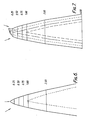
- FIG. 4 The predicted effects (from a computer model) obtained with various choices of bombardment angle ⁇ and bombardment time are shown, by way of example, schematically in Figures 4 to 7.
- Each of these Figures shows the bombardment of a stainless steel cutting edge with argon ions at a voltage of 1kV and with a current of 80 mA.
- the solid line shows the surface of the cutting edge before bombardment and the dashed (or other broken) line, the surface after bombardment; the figures on the right hand side shown the distance in micrometres from the ultimate tip.
- Figure 4 shows bombardment at an angle of 20° for 5 minutes. Facets having a semi-angle of 10° are formed resulting in a thinning of the blade.
- FIG 5 shows bombardment at an angle of 60° for 30 seconds (it should be noted that the scale of this Figure is much larger than that of Figure 4).
- Figure 6 shows the effect obtained by asymmetric treatment, one beam being aligned at 0° and the other at 30° and bombardment being effected for 10 minutes.
- the resulting cutting edge is asymmetric (chisel-shaped); such cutting edges are desirable in certain types of razor.
- Figure 7 shows the use of dual beam ion bombardment to rectify a fault arising from the mechanical finishing of a cutting edge.
- the initial cutting edge has a turned-over ultimate tip.
- FIG. 4 to 7 describe treatments in which a bombardment angle or angles is/are chosen and then maintained throughout the treatment.
- the bombardment angle of one or both ion sources can, however, be intermittently or continuously varied during the course of the treatment in order to obtain combinations of effects.
- FIG. 8 A preferred embodiment of apparatus for carrying out substrate shaping and the formation of a shaped coating thereon is shown in Figure 8.
- the apparatus is essentially the same as the apparatus of Figure 1 and the same elements have been given the same reference numerals, but the apparatus of Figure 8 additionally comprises an electron beam evaporation device 17 which is provided with a suitable power supply.
- the electron beam evaporator may be any suitable commercially available unit.
- the electron beam evaporator In use, the electron beam evaporator is not initially operated and the two ion sources are operated in order to obtain the desired form of substrate cutting edge. When this has been obtained, the electron beam evaporator is operated to vaporise the desired coating material or component thereof where the coating is a compound, and operation of the ion sources is continued. From the point when deposition is commenced the sputter removal rate due to the ion sources should, of course, be less than the deposition rate and operation of the ion sources may have to be adjusted to ensure this.
- Suitable conditions for the electron beam evaporation are, for example, a beam voltage of 5.5 to 10kV, preferably about 10kV, and a beam current of 100 to 500 mA, preferably 150 to 350 mA.
- the coating material or component thereof can be evaporated for the purpose of deposition in other ways, for example, by sputtering, resistive evaporation, or induction heating.
- Suitable coating materials include, for example, metal oxides, nitrides, carbides and borides, and mixtures of a metal and an oxide, nitride or carbide thereof.
- Preferred coating materials include, for example, alumina (sapphire), tungsten carbide, titanium nitride, boron carbide, boron nitride, and mixtures of boron and boron nitride, and diamond-like carbon.
- Nitride coatings for example TiN and BN, are preferably formed by electron beam evaporation of the metal, for example titanium or boron, with nitrogen present in the chamber 10 in an amount required for the coating to be formed of the desired metal nitride.
- Coatings consisting of a mixture of such a nitride and the corresponding metal, such as a coating of boron/boron nitride containing 10 atomic % of nitrogen, are also of interest. These coatings may be obtained by restricting the amount of nitrogen present in the chamber to that required to give the desired conversion of the deposited metal to its nitride.
- the boron/boron nitride mixture referred to above has a Vickers hardness of 3000 to 4000 kg/mm2 and is thus considerably harder than titanium nitride which has a Vickers hardness of 2000 kg/mm2.
- Carbide coatings for example TiC and B4C, are preferably formed in a similar way, but with a gaseous or vaporized hydrocarbon present in place of nitrogen, the amount of hydrocarbon being sufficient to provide the amount of carbon to form the desired carbide.
- Oxide coatings for example Al2O3, are preferably evaporated directly, but may be formed in a similar way, but with oxygen present in place of nitrogen and the amount of oxygen being sufficient to provide the amount required to form the desired oxide.
- a further coating material which may be used is diamond-like carbon (DLC), for which the formation of coatings can also be achieved by an alternative method. Since this material consists of carbon alone, it is possible to produce a coating by the introduction of a gaseous or vaporized hydrocarbon directly into the vacuum chamber or via the ion sources. Suitable hydrocarbons include, for example, methane, butane, propane and acetylene. The ion bombardment is, of course, carried out as described for other coating materials. In addition an RF glow discharge may be used in the deposition chamber to form the diamond-like carbon while simultaneously bombarding with an ion beam.
- DLC diamond-like carbon
- coatings formed of single compounds or mixtures may be formed by the method according to the invention.
- the formation of coatings in two or more layers is primarily of interest when the outer or final coating does not have the desired adhesion to the substrate cutting edge.
- a first coating is formed of a material which has good adhesion to the substrate and to which the desired outer coating has good adhesion, and the outer coating is then formed.
- An example is the improved adhesion of diamond-like carbon when deposited with an interlayer of a metal such as chromium or titanium.
- a phenomenon which has been observed during the ion beam shaping phase of the process is the formation of bands of material on the blade edges. These bands, best observed by optical microscopy, lie parallel to the ultimate tip of the blade.
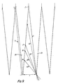
- FIG. 9 shows four blades in a stack, oriented as shown in Figure 1 and 8.
- the blades have a body thickness of t, which is typically 100 ⁇ m, and a cutting edge depth or facet length, f, which is typically 500 ⁇ m.
- t body thickness
- f cutting edge depth or facet length
- the cutting edge of blade 20 is shadowed from the ion beam from point A to Z by the tip of the adjacent blade 21; at an angle of 25°, the cutting edge is shadowed from B to Z, and so on.
- facet length of 500 ⁇ m it is only at bombardment angles of 6° or less that there is no shadowing effect on the facets, although for practical purposes angles of less than 10° produce no deleterious effects in use.
- the portion of the facets beyond the relevant points A, B, etc. is not bombarded by the ion beam, such that material sputtered off the bombarded portions of blades 20 and 21 can be redeposited on the unbombarded portion, thus building up a film of sputtered material. It is this material that is seen as bands on the facets. The formation of such bands is undesirable as the material in them is readily detached from the underlying substrate during use of the blades.
- This detachment leads, in turn, to loss of any further coatings deposited at subsequent stages of the process, such as the hard coating which may be deposited in the second stage of the present process, or the sputtered chromium or chromium-platinum, and polytetrafluoroethylene coatings which are conventionally applied to razor blade cutting edges; and loss of these coatings substantially reduces the performance of the blades.
- the shadowing has an undesirable effect during the deposition phase of the process in that deposited material in the region A, B, etc. to Z will not be subjected to simultaneous ion bombardment. This prevents the coating from being properly refined and shaped and, as a result, thick and poorly adherent coatings are obtained.
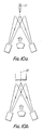
- the shadowing effect, and the formation of such undesirable bands can be avoided (i) by the use of low bombardment angles, that is of less than about 10°, (ii) by the use of spacers between the blades in the stack, and (iii) by rotation of the stack about an axis lying in the plane 15 ( Figures 1 and 8) and perpendicular to the blade edges.
- Figure 10a is a very diagrammatic representation of the arrangement shown in Figure 8 and shows the orientation of the blade edges as described hitherto; the Figure also shows an axis 22, lying in the plane 15 ( Figure 1 and 8) and perpendicular to the blade edges. If the blade stack is rotated about the axis 22 by 90°, the arrangement shown in Figure 10b is obtained.
- the orientation in Figure 10a will be taken as 0° and that in Figure 10b as 90° ; the angle of orientation of the blade stack between these limits will be referred to as ⁇ .
- the shaping of stainless steel razor blade cutting edges was carried out in apparatus as shown in Figure 1.
- the ion guns 13 and 14 were 30.0mm Kaufman ion guns; the guns were positioned symmetrically at a ⁇ angle of 25°.
- the substrate holder was positioned 300mm above the ion sources; at this distance, the ion beam had a diameter of about 100mm allowing a maximum current density of about 1mA/cm2.
- the energy of the ions was set at 1.5 kV.
- the workpiece was a stack of sharpened stainless steel razor blades and it was aligned as shown in the Figure.
- the cutting edges had been formed by conventional mechanical sharpening.
- the shape of the cutting edges was measured in a pre-selected portion of the edge before treatment using the technique described in GB-A-2130955.
- the chamber was closed, sealed and evacuated to a pressure of less than 10 ⁇ 6 mbar and 3.3 ml/min argon was than admitted into each of the ion guns, thus raising the chamber pressure to 1 x 10 ⁇ 4 mbar.
- the ion guns were activated and bombardment was carried out for 10 minutes using a beam current of 50 mA.
- the blades were removed from the chamber and their tip shape was re-measured in the same pre-selected portion of the edge as before treatment.
- the shape measurements indicate that the cutting edge had been thinned.
- the ion guns 13 and 14, their orientation, and the spacing of the workpiece holder from the ion guns were as described in Example 1.
- the electron beam evaporator 17 was a 10kV Electrotech ET15 unit; it was charged with boron.
- Stainless steel blades which had been mechanically sharpened were mounted in the workpiece holder and subjected to argon ion bombardment as described in Example 1 except that a negative bias of 3 kv was applied to the workpiece holder.
- a negative bias of 3 kv was applied to the workpiece holder.
- 20 ml/min of nitrogen was admitted into the chamber along with the 3.3 ml/min of argon into each source and while maintaining the beam voltage of the ion guns at 1.5 kV and the negative bias of -3kV applied to the workpiece holder, the beam current was increased from 50mA to 60mA.
- the electron beam evaporator was actuated using a beam voltage of 10kV and a beam current of 215 mA.
- the chamber pressure during this second, deposition, stage was maintained at 1.1 x 10 ⁇ 4 mbar.
- Example 2 was repeated, but with spacers between the blades in the stack and with rotation of the blades about a vertical axis (procedures (ii) and (iii) above in order to avoid the formation of shadowing bands.
- each blade in the stack was separated from the adjacent blades by a spacer having a thickness of one blade and (ii) the blade stack was rotated through a ⁇ angle of 65° so as to give a bombardment angle ⁇ of 10°.
- Ion beam sharpening was effected using a beam voltage of 1.5 kV and a beam current of 45 mA on each ion source for a period of 5 minutes; the substrate bias was zero.
Claims (16)
- Verfahren zur Herstellung oder Modifikation der Schneidenkanten von Rasierklingen, umfassend den Ionenbeschuß eines Stapels Rasierklingen durch zwei Ionenquellen in einer Vakuumkammer, wobei die Ionenquelle auf den gegenüberliegenden Seiten einer Ebene angeordnet ist, die innerhalb des Stapels und parallel zu den Hauptflächen der klingen liegt, und wobei die Ionenquellen die Achsen ihrer Ionenstrahlen auf die Kanten der Rasierklingen in dem Stapel gerichtet haben und der Ionenbeschuß mit Ionen von ausreichender Masse und Energie in bezug auf das Material erfolgt, aus dem die Rasierklingen hergestellt werden, um eine Sputterentfernung des Materials der Klingen auf deren beiden Seiten zu bewirken und dadurch ihre Schneidenkanten herzustellen oder zu modifizieren.
- Verfahren nach Anspruch 1, bei welchem der Ionenbeschuß zur Schaffung von Schneidenkanten ausgeführt wird, bei denen gilt:

- Verfahren nach Anspruch 1 oder 2, bei welchem die Rasierklingen aus rostfreiem Stahl hergestellt werden.
- Verfahren nach Anspruch 1 oder 2, bei welchem die Rasierklingen aus einem Material hergestellt werden, das eine größere Streckgrenze oder Bruchfestigkeit als rostfreier Stahl hat.
- Verfahren nach einem der Ansprüche 1 bis 4, bei welchem die Beschußionen Argon-, Stickstoff- oder Sauerstoffionen sind.
- Verfahren nach einem der Ansprüche 1 bis 4, bei welchem der Ionenbeschuß mit den bei einer Strahlspannung von 1.000 bis 1.500 V und einem Strahlstrom von 40 bis 80 mA betätigten Ionenstrahlsystemen durchgeführt wird und wobei Gas zur Bildung der Beschußionen von 3 bis 5 ml/min zugeführt wird und der Rasierklingenstapel eine Vorspannung von 0 bis -3 kV hat.
- Verfahren nach einem der Ansprüche 1 bis 6, bei welchem nach der Herstellung oder Modifikation der Schneidenkanten ein von dem Material der Rasierklinge unterschiedliches Material auf den unter Beschuß gesetzten Oberflächen der Klingen durch Verdampfung abgeschieden wird, währen der Ionenbeschuß fortgesetzt wird, um die Beschichtung des abgeschiedenen Materials in der abgeschiedenen Form zu verfeinern und zu formen, wobei die Geschwindigkeit der Materialentfernung durch den Ionenbeschuß kleiner ist als die Geschwindigkeit der Abscheidung.
- Verfahren nach Anspruch 7, bei welchem die Rasierklingen aus rostfreiem Stahl hergestellt werden und das abgeschiedene Material, welches auf den Schneidenkanten beschichtet ist, ein Material mit größerer Streckgrenze oder Bruchfestigkeit ist als rostfreier Stahl.
- Verfahren nach Anspruch 8, bei welchem das abgeschiedene Material Saphir, Bornitrid, ein Gemisch von Bor/Bornitrid, Titannitrid oder diamantähnlicher Kohlenstoff ist.
- Verfahren nach Anspruch 8 und 9, bei welchem die Stufen des anfänglichen Ionenbeschusses und danach das Beschichten mit Ionenbeschuß ausgeführt werden, um beschichtete Schneidenkanten zu schaffen, in denen

worin sind: w die Schneidenbreite in µm der Schneidenkante bei einer Entfernung d in µm von der Schneide, a ein Proportionalitätsfaktor zwischen 0, 7 und 1, 0, n ein Exponent mit einem Wert zwischen 0,65 und 0,75, m der Quotient der Streckgrenze von abgeschiedenem Material und rostfreiem Stahl, und h die Dicke in µm der Beschichtung in der Entfernung d in µm von der Schneide. - Verfahren nach einem der Ansprüche 7 bis 10, in welchem das abgeschiedene Material oder eine Komponente davon mit Hilfe der Elektronenstrahlverdampfung aufgedampft wird.
- Verfahren nach Anspruch 11, bei welchem der Elektronenstrahlverdampfer bei einer Strahlspannung von etwa 10 kV und einem Strahlstrom von 150 bis 150 mA betätigt wird.
- Verfahren nach einem der Ansprüche 1 bis 12, bei welchem Ionenbeschuß mit der Ebene ausgeführt wird, welche innerhalb des Stapels und parallel zu den Hauptflächen der Klingen liegt und mit einer die Achsen beider Ionenstrahlen enthaltenen Ebene einen anderen Winkel als 90° bildet, welcher Winkel so ist, daß im wesentlichen die Gesamtheit der Schneidenkanten der Klingen für die Ionenstrahlen zugänglich ist.
- Vorrichtung zur Durchführung des Verfahrens nach Anspruch 1, welche eine hermetisch abschließbare Vakuumkammer umfaßt und einen darin angeordneten Werkstückhalter und zwei Ionenquellen zum Durchführen des Ionenbeschusses, wobei die Ionenquellen so angeordnet sind, daß sie sich auf gegenüberliegenden Seiten einer Ebene befinden, die innerhalb eines in dem Werkstückhalter befestigten Stapels Rasierklingen enthalten ist, und so angeordnet sind, daß die Achsen der von Ionenquellen erzeugten Ionenstrahlen auf die Kanten der Rasierklingen gerichtet sind, wenn ein Stapel von Klingen derart befestigt ist.
- Vorrichtung nach Anspruch 14, bei welcher jede Ionenquelle in bezug auf einen Bogen radial ausgerichtet ist, der zu einer Achse zentriert ist, welche in einen Stapel von so befestigten Klingen liegt, und entlang diesem Bogen drehbar beweglich ist.
- Vorrichtung nach Anspruch 14 oder 15, in welcher die Vakuumkammer zusätzlich einen Elektronenstrahlverdampfer enthält, der zur Abscheidung von Material auf einen Stapel von Klingen angeordnet ist, der in den Werkstückhalter befestigt ist.
Priority Applications (1)
| Application Number | Priority Date | Filing Date | Title |
|---|---|---|---|
| AT89116550T ATE86675T1 (de) | 1988-09-19 | 1989-09-07 | Verfahren und vorrichtung zur herstellung oder modifikation von schneidkanten. |
Applications Claiming Priority (2)
| Application Number | Priority Date | Filing Date | Title |
|---|---|---|---|
| GB888821944A GB8821944D0 (en) | 1988-09-19 | 1988-09-19 | Method & apparatus for forming surface of workpiece |
| GB8821944 | 1988-09-19 |
Publications (2)
| Publication Number | Publication Date |
|---|---|
| EP0363648A1 EP0363648A1 (de) | 1990-04-18 |
| EP0363648B1 true EP0363648B1 (de) | 1993-03-10 |
Family
ID=10643845
Family Applications (1)
| Application Number | Title | Priority Date | Filing Date |
|---|---|---|---|
| EP89116550A Expired - Lifetime EP0363648B1 (de) | 1988-09-19 | 1989-09-07 | Verfahren und Vorrichtung zur Herstellung oder Modifikation von Schneidkanten |
Country Status (12)
| Country | Link |
|---|---|
| US (1) | US5032243A (de) |
| EP (1) | EP0363648B1 (de) |
| JP (1) | JP2779453B2 (de) |
| AT (1) | ATE86675T1 (de) |
| BR (1) | BR8907055A (de) |
| CA (1) | CA1338053C (de) |
| DE (1) | DE68905286T2 (de) |
| ES (1) | ES2038810T3 (de) |
| GB (1) | GB8821944D0 (de) |
| GR (1) | GR3007307T3 (de) |
| IN (1) | IN177196B (de) |
| WO (1) | WO1990003455A1 (de) |
Cited By (3)
| Publication number | Priority date | Publication date | Assignee | Title |
|---|---|---|---|---|
| US9751230B2 (en) | 2014-05-19 | 2017-09-05 | The Gillette Company | Razor blades |
| US20210276211A1 (en) * | 2020-03-05 | 2021-09-09 | John Robert Harris | Razor blade with improved asymmetric profile |
| US11230024B2 (en) | 2014-12-22 | 2022-01-25 | Bic-Violex Sa | Razor blade |
Families Citing this family (83)
| Publication number | Priority date | Publication date | Assignee | Title |
|---|---|---|---|---|
| JP2932650B2 (ja) * | 1990-09-17 | 1999-08-09 | 松下電器産業株式会社 | 微細構造物の製造方法 |
| US6725072B2 (en) * | 1990-10-06 | 2004-04-20 | Hema Metrics, Inc. | Sensor for transcutaneous measurement of vascular access blood flow |
| US5296272A (en) * | 1990-10-10 | 1994-03-22 | Hughes Aircraft Company | Method of implanting ions from a plasma into an object |
| US5218179A (en) * | 1990-10-10 | 1993-06-08 | Hughes Aircraft Company | Plasma source arrangement for ion implantation |
| US5142785A (en) * | 1991-04-26 | 1992-09-01 | The Gillette Company | Razor technology |
| US5154023A (en) * | 1991-06-11 | 1992-10-13 | Spire Corporation | Polishing process for refractory materials |
| US5232568A (en) * | 1991-06-24 | 1993-08-03 | The Gillette Company | Razor technology |
| ZA928617B (en) * | 1991-11-15 | 1993-05-11 | Gillette Co | Shaving system. |
| US5669144A (en) * | 1991-11-15 | 1997-09-23 | The Gillette Company | Razor blade technology |
| US5295305B1 (en) * | 1992-02-13 | 1996-08-13 | Gillette Co | Razor blade technology |
| BR9507514A (pt) * | 1994-04-25 | 1997-09-02 | Gillette Co | Processo para formação de uma lâmina de barbear l mina unidade de barbear e processo para aplicação de um revestimento duro de carbono a uma lâmina |
| US5958134A (en) * | 1995-06-07 | 1999-09-28 | Tokyo Electron Limited | Process equipment with simultaneous or sequential deposition and etching capabilities |
| US5916114A (en) * | 1995-09-21 | 1999-06-29 | Fisher-Barton, Inc. | High hardness boron steel rotary blade |
| US6468642B1 (en) | 1995-10-03 | 2002-10-22 | N.V. Bekaert S.A. | Fluorine-doped diamond-like coatings |
| US5638251A (en) * | 1995-10-03 | 1997-06-10 | Advanced Refractory Technologies, Inc. | Capacitive thin films using diamond-like nanocomposite materials |
| JPH10130865A (ja) * | 1996-09-06 | 1998-05-19 | Sanyo Electric Co Ltd | 硬質炭素被膜基板及びその形成方法 |
| WO1998004382A1 (en) * | 1996-07-30 | 1998-02-05 | Drukker International B.V. | A method of producing a cutting tool insert |
| EP1067210A3 (de) * | 1996-09-06 | 2002-11-13 | Sanyo Electric Co., Ltd. | Verfahren zur Abscheidung eines harten Kohlenstoff-Filmes auf einem Substrat und Klinge für einen elektrischen Rasierer |
| CA2234966A1 (en) | 1997-06-10 | 1998-12-10 | Brian G. Balistee | Improved blade edge |
| US6077572A (en) * | 1997-06-18 | 2000-06-20 | Northeastern University | Method of coating edges with diamond-like carbon |
| JP3555844B2 (ja) | 1999-04-09 | 2004-08-18 | 三宅 正二郎 | 摺動部材およびその製造方法 |
| ATE231427T1 (de) * | 1999-06-18 | 2003-02-15 | Voith Paper Patent Gmbh | Schleifscheibe, schleifsystem und verfahren zum schleifen eines messers |
| IL138710A0 (en) | 1999-10-15 | 2001-10-31 | Newman Martin H | Atomically sharp edge cutting blades and method for making same |
| US6684513B1 (en) * | 2000-02-29 | 2004-02-03 | The Gillette Company | Razor blade technology |
| JP4741056B2 (ja) * | 2000-06-05 | 2011-08-03 | 株式会社貝印刃物開発センター | 刃部材及びその刃先の製造方法 |
| US20030082720A1 (en) * | 2001-07-17 | 2003-05-01 | Lifton Richard P. | Compositions methods and kits relating to treating and diagnosing hypertension |
| US7387742B2 (en) | 2002-03-11 | 2008-06-17 | Becton, Dickinson And Company | Silicon blades for surgical and non-surgical use |
| AU2003231967B2 (en) * | 2002-03-11 | 2006-10-12 | Beaver-Visitec International (Us), Inc. | System and method for the manufacture of surgical blades |
| KR100466536B1 (ko) * | 2002-05-10 | 2005-01-15 | 한국원자력연구소 | 이온 조사에 의한 이용기 날의 표면처리 방법 |
| JP4496701B2 (ja) * | 2002-05-27 | 2010-07-07 | パナソニック電工株式会社 | 刃物の加工方法及びその加工装置及び電気かみそり用内刃 |
| JP2004138128A (ja) | 2002-10-16 | 2004-05-13 | Nissan Motor Co Ltd | 自動車エンジン用摺動部材 |
| US6969198B2 (en) | 2002-11-06 | 2005-11-29 | Nissan Motor Co., Ltd. | Low-friction sliding mechanism |
| US7866343B2 (en) | 2002-12-18 | 2011-01-11 | Masco Corporation Of Indiana | Faucet |
| US7866342B2 (en) | 2002-12-18 | 2011-01-11 | Vapor Technologies, Inc. | Valve component for faucet |
| US8220489B2 (en) | 2002-12-18 | 2012-07-17 | Vapor Technologies Inc. | Faucet with wear-resistant valve component |
| US8555921B2 (en) | 2002-12-18 | 2013-10-15 | Vapor Technologies Inc. | Faucet component with coating |
| US20040172832A1 (en) * | 2003-03-04 | 2004-09-09 | Colin Clipstone | Razor blade |
| US20090007436A1 (en) * | 2003-03-10 | 2009-01-08 | Daskal Vadim M | Silicon blades for surgical and non-surgical use |
| US20050155955A1 (en) * | 2003-03-10 | 2005-07-21 | Daskal Vadim M. | Method for reducing glare and creating matte finish of controlled density on a silicon surface |
| JP3891433B2 (ja) | 2003-04-15 | 2007-03-14 | 日産自動車株式会社 | 燃料噴射弁 |
| US20040222082A1 (en) * | 2003-05-05 | 2004-11-11 | Applied Materials, Inc. | Oblique ion milling of via metallization |
| EP1479946B1 (de) | 2003-05-23 | 2012-12-19 | Nissan Motor Co., Ltd. | Kolben für eine Brennkraftmaschine |
| EP1482190B1 (de) | 2003-05-27 | 2012-12-05 | Nissan Motor Company Limited | Wälzkörper |
| JP4863152B2 (ja) | 2003-07-31 | 2012-01-25 | 日産自動車株式会社 | 歯車 |
| KR101003865B1 (ko) | 2003-08-06 | 2010-12-30 | 닛산 지도우샤 가부시키가이샤 | 저마찰 접동 기구, 저마찰제 조성물 및 마찰 감소 방법 |
| JP4973971B2 (ja) | 2003-08-08 | 2012-07-11 | 日産自動車株式会社 | 摺動部材 |
| JP2005054617A (ja) | 2003-08-08 | 2005-03-03 | Nissan Motor Co Ltd | 動弁機構 |
| JP4117553B2 (ja) | 2003-08-13 | 2008-07-16 | 日産自動車株式会社 | チェーン駆動装置 |
| DE602004008547T2 (de) | 2003-08-13 | 2008-05-21 | Nissan Motor Co., Ltd., Yokohama | Struktur zur Verbindung von einem Kolben mit einer Kurbelwelle |
| JP4539205B2 (ja) | 2003-08-21 | 2010-09-08 | 日産自動車株式会社 | 冷媒圧縮機 |
| US7771821B2 (en) | 2003-08-21 | 2010-08-10 | Nissan Motor Co., Ltd. | Low-friction sliding member and low-friction sliding mechanism using same |
| EP1508611B1 (de) | 2003-08-22 | 2019-04-17 | Nissan Motor Co., Ltd. | Getriebe enthaltend eine getriebeölzusammensetzung |
| EP1662970A2 (de) * | 2003-09-17 | 2006-06-07 | Becton, Dickinson and Company | System und verfahren zur erzeugung von linearen und nichtlinearen furchen in silizium und anderen kristallinen materialien mit einem router |
| US7824498B2 (en) * | 2004-02-24 | 2010-11-02 | Applied Materials, Inc. | Coating for reducing contamination of substrates during processing |
| US7396484B2 (en) * | 2004-04-30 | 2008-07-08 | Becton, Dickinson And Company | Methods of fabricating complex blade geometries from silicon wafers and strengthening blade geometries |
| US7673541B2 (en) | 2004-06-03 | 2010-03-09 | The Gillette Company | Colored razor blades |
| US7556699B2 (en) * | 2004-06-17 | 2009-07-07 | Cooper Clark Vantine | Method of plasma nitriding of metals via nitrogen charging |
| US7284461B2 (en) | 2004-12-16 | 2007-10-23 | The Gillette Company | Colored razor blades |
| WO2006079360A1 (en) * | 2005-01-27 | 2006-08-03 | Bic Violex Sa | Razor blade, razor head, razor and method of manufacturing a razor blade |
| US20060277767A1 (en) * | 2005-06-14 | 2006-12-14 | Shuwei Sun | Razor blades |
| JP2007061212A (ja) * | 2005-08-29 | 2007-03-15 | Kai R & D Center Co Ltd | 刃体の刃縁の成形方法 |
| US20070051622A1 (en) * | 2005-09-02 | 2007-03-08 | Applied Materials, Inc. | Simultaneous ion milling and sputter deposition |
| US20070124944A1 (en) * | 2005-11-30 | 2007-06-07 | Eveready Battery Company, Inc. | Razor blade and method of making it |
| US20070131060A1 (en) * | 2005-12-14 | 2007-06-14 | The Gillette Company | Automated control of razor blade colorization |
| AU2007215243A1 (en) | 2006-02-10 | 2007-08-23 | Eveready Battery Company, Inc. | Multi-layer coating for razor blades |
| US20070224350A1 (en) * | 2006-03-21 | 2007-09-27 | Sandvik Intellectual Property Ab | Edge coating in continuous deposition line |
| US8443519B2 (en) * | 2006-09-15 | 2013-05-21 | The Gillette Company | Blade supports for use in shaving systems |
| JP5210627B2 (ja) * | 2007-12-27 | 2013-06-12 | 永田精機株式会社 | 刃部材及び刃部材の刃縁の加工装置 |
| US9079321B2 (en) * | 2008-07-16 | 2015-07-14 | The Gillette Company | Razor blades |
| MX348741B (es) * | 2009-05-15 | 2017-06-22 | The Gillette Company * | Recubrimiento de hoja de rasuradora. |
| US20130014395A1 (en) * | 2011-07-14 | 2013-01-17 | Ashok Bakul Patel | Razor blades having a large tip radius |
| JP5924094B2 (ja) | 2012-04-18 | 2016-05-25 | 新明和工業株式会社 | 刃物、その製造方法およびそれを製造するためのプラズマ装置 |
| JP5956855B2 (ja) * | 2012-07-04 | 2016-07-27 | 日本航空電子工業株式会社 | 切れ刃エッジの加工方法及び器具の製造方法 |
| US11230025B2 (en) | 2015-11-13 | 2022-01-25 | The Gillette Company Llc | Razor blade |
| US20180029241A1 (en) * | 2016-07-29 | 2018-02-01 | Liquidmetal Coatings, Llc | Method of forming cutting tools with amorphous alloys on an edge thereof |
| US11654588B2 (en) | 2016-08-15 | 2023-05-23 | The Gillette Company Llc | Razor blades |
| RU2637453C1 (ru) * | 2016-11-02 | 2017-12-04 | Владимир Николаевич Назаров | Способ упрочнения стальных изделий |
| US11759965B2 (en) | 2020-04-16 | 2023-09-19 | The Gillette Company Llc | Multi-layer coatings for a razor blade |
| CN115379933A (zh) | 2020-04-16 | 2022-11-22 | 吉列有限责任公司 | 用于剃刀刀片的涂层 |
| CA3173547A1 (en) | 2020-04-16 | 2021-10-21 | The Gillette Company Llc | Coatings for a razor blade |
| KR20230081311A (ko) * | 2021-11-30 | 2023-06-07 | 주식회사 도루코 | 면도날 |
| US20230373120A1 (en) | 2022-05-20 | 2023-11-23 | The Gillette Company Llc | Method of coating a razor blade |
| US20230373121A1 (en) | 2022-05-20 | 2023-11-23 | The Gillette Company Llc | Non-fluorinated organic coating material for a razor blade |
Family Cites Families (5)
| Publication number | Priority date | Publication date | Assignee | Title |
|---|---|---|---|---|
| US3740327A (en) * | 1969-06-03 | 1973-06-19 | Warner Lambert Co | Sputter coating apparatus with shrouding means |
| US3761373A (en) * | 1971-07-09 | 1973-09-25 | Gillette Co | Process for producing an improved cutting tool |
| US4128765A (en) * | 1976-10-29 | 1978-12-05 | Joseph Franks | Ion beam machining techniques and apparatus |
| US4599135A (en) * | 1983-09-30 | 1986-07-08 | Hitachi, Ltd. | Thin film deposition |
| GB8600829D0 (en) * | 1986-01-23 | 1986-02-19 | Gillette Co | Formation of hard coatings on cutting edges |
-
1988
- 1988-09-19 GB GB888821944A patent/GB8821944D0/en active Pending
-
1989
- 1989-09-06 US US07/460,858 patent/US5032243A/en not_active Expired - Lifetime
- 1989-09-06 JP JP1510104A patent/JP2779453B2/ja not_active Expired - Lifetime
- 1989-09-06 WO PCT/US1989/003850 patent/WO1990003455A1/en unknown
- 1989-09-06 BR BR898907055A patent/BR8907055A/pt not_active IP Right Cessation
- 1989-09-07 ES ES198989116550T patent/ES2038810T3/es not_active Expired - Lifetime
- 1989-09-07 DE DE8989116550T patent/DE68905286T2/de not_active Expired - Lifetime
- 1989-09-07 AT AT89116550T patent/ATE86675T1/de active
- 1989-09-07 EP EP89116550A patent/EP0363648B1/de not_active Expired - Lifetime
- 1989-09-08 IN IN807DE1989 patent/IN177196B/en unknown
- 1989-09-18 CA CA000611798A patent/CA1338053C/en not_active Expired - Fee Related
-
1993
- 1993-03-11 GR GR920403271T patent/GR3007307T3/el unknown
Cited By (3)
| Publication number | Priority date | Publication date | Assignee | Title |
|---|---|---|---|---|
| US9751230B2 (en) | 2014-05-19 | 2017-09-05 | The Gillette Company | Razor blades |
| US11230024B2 (en) | 2014-12-22 | 2022-01-25 | Bic-Violex Sa | Razor blade |
| US20210276211A1 (en) * | 2020-03-05 | 2021-09-09 | John Robert Harris | Razor blade with improved asymmetric profile |
Also Published As
| Publication number | Publication date |
|---|---|
| JP2779453B2 (ja) | 1998-07-23 |
| DE68905286D1 (de) | 1993-04-15 |
| EP0363648A1 (de) | 1990-04-18 |
| DE68905286T2 (de) | 1993-08-05 |
| ES2038810T3 (es) | 1993-08-01 |
| IN177196B (de) | 1996-11-30 |
| WO1990003455A1 (en) | 1990-04-05 |
| ATE86675T1 (de) | 1993-03-15 |
| GB8821944D0 (en) | 1988-10-19 |
| JPH03501458A (ja) | 1991-04-04 |
| CA1338053C (en) | 1996-02-13 |
| GR3007307T3 (de) | 1993-07-30 |
| US5032243A (en) | 1991-07-16 |
| BR8907055A (pt) | 1991-01-02 |
Similar Documents
| Publication | Publication Date | Title |
|---|---|---|
| EP0363648B1 (de) | Verfahren und Vorrichtung zur Herstellung oder Modifikation von Schneidkanten | |
| US4933058A (en) | Formation of hard coatings on cutting edges | |
| US5992268A (en) | Amorphous diamond coating of blades | |
| Whitmell et al. | The deposition of hard surface layers by hydrocarbon cracking in a glow discharge | |
| EP0532501B1 (de) | Rasierklingentechnologie | |
| US5488774A (en) | Cutting edges | |
| US5056227A (en) | Razor blade technology | |
| US3761372A (en) | Method for producing an improved cutting tool | |
| CA1337560C (en) | Edged medical tool and method for preparation thereof | |
| EP0567300B1 (de) | Messerklingen | |
| CA2290514C (en) | A method of coating edges with diamond-like carbon | |
| US5121660A (en) | Razor blade technology | |
| EP0255834B1 (de) | Bildung harter beschichtungen auf schneidrändern | |
| Halverson et al. | Effects of charge neutralization on ion‐beam‐deposited boron nitride films | |
| JP7356975B2 (ja) | Al2O3の蒸着のためのPVD法と少なくとも一のAl2O3層を有する被覆切削工具 | |
| RU2048607C1 (ru) | Способ нанесения защитных покрытий | |
| JPH0241195A (ja) | 耐久性切断刃 | |
| MXPA99011903A (en) | A method of coating edgeswith diamond-like carbon | |
| JPH04344211A (ja) | ダイヤモンド様保護膜を有する金型とその製造方法 |
Legal Events
| Date | Code | Title | Description |
|---|---|---|---|
| PUAI | Public reference made under article 153(3) epc to a published international application that has entered the european phase |
Free format text: ORIGINAL CODE: 0009012 |
|
| AK | Designated contracting states |
Kind code of ref document: A1 Designated state(s): AT BE CH DE ES FR GB GR IT LI LU NL SE |
|
| 17P | Request for examination filed |
Effective date: 19900823 |
|
| 17Q | First examination report despatched |
Effective date: 19920414 |
|
| GRAA | (expected) grant |
Free format text: ORIGINAL CODE: 0009210 |
|
| AK | Designated contracting states |
Kind code of ref document: B1 Designated state(s): AT BE CH DE ES FR GB GR IT LI LU NL SE |
|
| REF | Corresponds to: |
Ref document number: 86675 Country of ref document: AT Date of ref document: 19930315 Kind code of ref document: T |
|
| REF | Corresponds to: |
Ref document number: 68905286 Country of ref document: DE Date of ref document: 19930415 |
|
| ITF | It: translation for a ep patent filed |
Owner name: STUDIO TORTA SOCIETA' SEMPLICE |
|
| ET | Fr: translation filed | ||
| REG | Reference to a national code |
Ref country code: GR Ref legal event code: FG4A Free format text: 3007307 |
|
| REG | Reference to a national code |
Ref country code: ES Ref legal event code: FG2A Ref document number: 2038810 Country of ref document: ES Kind code of ref document: T3 |
|
| PLBE | No opposition filed within time limit |
Free format text: ORIGINAL CODE: 0009261 |
|
| STAA | Information on the status of an ep patent application or granted ep patent |
Free format text: STATUS: NO OPPOSITION FILED WITHIN TIME LIMIT |
|
| 26N | No opposition filed | ||
| EPTA | Lu: last paid annual fee | ||
| EAL | Se: european patent in force in sweden |
Ref document number: 89116550.8 |
|
| PGFP | Annual fee paid to national office [announced via postgrant information from national office to epo] |
Ref country code: LU Payment date: 19980724 Year of fee payment: 10 |
|
| PGFP | Annual fee paid to national office [announced via postgrant information from national office to epo] |
Ref country code: GR Payment date: 19980728 Year of fee payment: 10 |
|
| PGFP | Annual fee paid to national office [announced via postgrant information from national office to epo] |
Ref country code: AT Payment date: 19980806 Year of fee payment: 10 |
|
| PGFP | Annual fee paid to national office [announced via postgrant information from national office to epo] |
Ref country code: FR Payment date: 19980902 Year of fee payment: 10 |
|
| PGFP | Annual fee paid to national office [announced via postgrant information from national office to epo] |
Ref country code: SE Payment date: 19980903 Year of fee payment: 10 |
|
| PGFP | Annual fee paid to national office [announced via postgrant information from national office to epo] |
Ref country code: ES Payment date: 19980921 Year of fee payment: 10 |
|
| PGFP | Annual fee paid to national office [announced via postgrant information from national office to epo] |
Ref country code: CH Payment date: 19981012 Year of fee payment: 10 Ref country code: BE Payment date: 19981012 Year of fee payment: 10 |
|
| PG25 | Lapsed in a contracting state [announced via postgrant information from national office to epo] |
Ref country code: LU Free format text: LAPSE BECAUSE OF NON-PAYMENT OF DUE FEES Effective date: 19990907 Ref country code: AT Free format text: LAPSE BECAUSE OF NON-PAYMENT OF DUE FEES Effective date: 19990907 |
|
| PG25 | Lapsed in a contracting state [announced via postgrant information from national office to epo] |
Ref country code: ES Free format text: LAPSE BECAUSE OF NON-PAYMENT OF DUE FEES Effective date: 19990908 |
|
| PG25 | Lapsed in a contracting state [announced via postgrant information from national office to epo] |
Ref country code: SE Free format text: THE PATENT HAS BEEN ANNULLED BY A DECISION OF A NATIONAL AUTHORITY Effective date: 19990929 |
|
| PG25 | Lapsed in a contracting state [announced via postgrant information from national office to epo] |
Ref country code: BE Free format text: LAPSE BECAUSE OF NON-PAYMENT OF DUE FEES Effective date: 19990930 Ref country code: GR Free format text: LAPSE BECAUSE OF NON-PAYMENT OF DUE FEES Effective date: 19990930 Ref country code: LI Free format text: LAPSE BECAUSE OF NON-PAYMENT OF DUE FEES Effective date: 19990930 Ref country code: CH Free format text: LAPSE BECAUSE OF NON-PAYMENT OF DUE FEES Effective date: 19990930 |
|
| BERE | Be: lapsed |
Owner name: THE GILLETTE CY Effective date: 19990930 |
|
| EUG | Se: european patent has lapsed |
Ref document number: 89116550.8 |
|
| REG | Reference to a national code |
Ref country code: CH Ref legal event code: PL |
|
| PG25 | Lapsed in a contracting state [announced via postgrant information from national office to epo] |
Ref country code: FR Free format text: LAPSE BECAUSE OF NON-PAYMENT OF DUE FEES Effective date: 20000531 |
|
| REG | Reference to a national code |
Ref country code: FR Ref legal event code: ST |
|
| REG | Reference to a national code |
Ref country code: GB Ref legal event code: IF02 |
|
| REG | Reference to a national code |
Ref country code: ES Ref legal event code: FD2A Effective date: 20001013 |
|
| PG25 | Lapsed in a contracting state [announced via postgrant information from national office to epo] |
Ref country code: IT Free format text: LAPSE BECAUSE OF NON-PAYMENT OF DUE FEES;WARNING: LAPSES OF ITALIAN PATENTS WITH EFFECTIVE DATE BEFORE 2007 MAY HAVE OCCURRED AT ANY TIME BEFORE 2007. THE CORRECT EFFECTIVE DATE MAY BE DIFFERENT FROM THE ONE RECORDED. Effective date: 20050907 |
|
| PGFP | Annual fee paid to national office [announced via postgrant information from national office to epo] |
Ref country code: NL Payment date: 20080813 Year of fee payment: 20 |
|
| PGFP | Annual fee paid to national office [announced via postgrant information from national office to epo] |
Ref country code: GB Payment date: 20080808 Year of fee payment: 20 |
|
| PGFP | Annual fee paid to national office [announced via postgrant information from national office to epo] |
Ref country code: DE Payment date: 20080930 Year of fee payment: 20 |
|
| REG | Reference to a national code |
Ref country code: GB Ref legal event code: PE20 Expiry date: 20090906 |
|
| NLV7 | Nl: ceased due to reaching the maximum lifetime of a patent |
Effective date: 20090907 |
|
| PG25 | Lapsed in a contracting state [announced via postgrant information from national office to epo] |
Ref country code: NL Free format text: LAPSE BECAUSE OF EXPIRATION OF PROTECTION Effective date: 20090907 Ref country code: GB Free format text: LAPSE BECAUSE OF EXPIRATION OF PROTECTION Effective date: 20090906 |