EP0361717A1 - Aircraft cabin divider - Google Patents
Aircraft cabin divider Download PDFInfo
- Publication number
- EP0361717A1 EP0361717A1 EP89309147A EP89309147A EP0361717A1 EP 0361717 A1 EP0361717 A1 EP 0361717A1 EP 89309147 A EP89309147 A EP 89309147A EP 89309147 A EP89309147 A EP 89309147A EP 0361717 A1 EP0361717 A1 EP 0361717A1
- Authority
- EP
- European Patent Office
- Prior art keywords
- divider
- panel
- seat
- frame
- reclinable
- Prior art date
- Legal status (The legal status is an assumption and is not a legal conclusion. Google has not performed a legal analysis and makes no representation as to the accuracy of the status listed.)
- Granted
Links
- 230000000063 preceeding effect Effects 0.000 claims 1
- 210000003141 lower extremity Anatomy 0.000 description 4
- 239000007787 solid Substances 0.000 description 4
- 238000010276 construction Methods 0.000 description 2
- 210000003414 extremity Anatomy 0.000 description 2
- 230000000694 effects Effects 0.000 description 1
- 239000000463 material Substances 0.000 description 1
- 239000002184 metal Substances 0.000 description 1
- 238000007493 shaping process Methods 0.000 description 1
- 210000001364 upper extremity Anatomy 0.000 description 1
- 230000000007 visual effect Effects 0.000 description 1
Images


Classifications
-
- B—PERFORMING OPERATIONS; TRANSPORTING
- B64—AIRCRAFT; AVIATION; COSMONAUTICS
- B64D—EQUIPMENT FOR FITTING IN OR TO AIRCRAFT; FLIGHT SUITS; PARACHUTES; ARRANGEMENT OR MOUNTING OF POWER PLANTS OR PROPULSION TRANSMISSIONS IN AIRCRAFT
- B64D11/00—Passenger or crew accommodation; Flight-deck installations not otherwise provided for
- B64D11/0023—Movable or removable cabin dividers, e.g. for class separation
Definitions
- the present invention relates to aircraft cabin dividers primarily for dividing an aircraft cabin into sections catering exclusively for first class, business class and tourist class passengers.
- Movable cabin dividers are well known in the airline industry for separating passengers travelling on differing fare structures according to provided facilities and comfort, and are predominantly in the form of curtains attached to structural support members engaging railed tracks which run up and down the aircraft cabin.
- curtain dividers represent an unsightly intrusion on aircraft cabin aesthetics, and moreover do not give that appearance necessary properly to distinguish one aircraft section from the other. This latter aspect is important when consideration is given to airline profitability in terms of the need to attract passengers to the business class section of an aircraft and the increased revenue which that produces compared to that generated from economy class demand and usage.
- a further problem with solid dividers is in relation to the need to reposition them to facilitate in-flight movie viewing because of the fact that the movie video is placed at the forward end of the aircraft cabin.
- an aircraft cabin divider comprising a divider frame movable between selected positions along the aircraft cabin, one or more divider panels of the divider frame, attachment means for attaching one end of the or each divider panel to the top of a reclinable aircraft seat, and extendible-retractable means attached between the other end of the or each divider panel and said divider frame, said extendible-retractable means permitting said other end of the or each divider panel to move with respect to said divider frame as the reclinable seat to which a respective one of the divider panels is attached is moved between selectable reclinable positions thereby to maintain the attitude of that divider panel at least substantially constant.
- the extendible retractable means is in the form of a pair of pivotally connected arms, the free end of one arm being attached to the divider frame, with the free end of the other arm pivotally attached to a respective divider panel, with the pivotally connected arms being urged together by means of a spring mounted between them.
- the pivotally connected arms separate allowing the top of the divider panel to move outwardly and downwardly against the action of the return spring in a controlled manner, and in such a way as to allow the divider panel to maintain a substantially constant attitude.
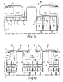
- the cabin divider shown in Figures 1a and lb of the drawings comprises a cabin divider support frame F1 and F2 designed for use in narrow or wide bodied aircrafts respectively.
- Each frame F1 and F2 is provided with a series of divider panels 1 which hang from the lower limbs LL1 and LL2 of the frames F1 and F2 and between those lower limbs and the top of a respective aircraft seat S.
- Each divider panel 1 is attachable at its lower end E to a respective reclinable seat S by means of a mechanical fastener or velcro flap (not shown), the latter fastening allowing the panels 1 to be positioned along a row of seats at any selected interval, along the length of the aircraft cabin C.
- Each panel 1, as seen better in Figure 3, is comprised of two portions 2 and 3 which are slightly inclined, one with respect to the other.
- each divider panel 1 is connectable by means of two extendible-retractable devices 5 mounted respectively between the corners of the top edge of the panel 1 and the lower limbs LL1 , LL2 of the divider frames F1 , F2 as shown.
- Each extendible-retractable device 5 comprises a pair of pivotally mounted arms 6, 7 the free end of one arm 6 of which is either permanently secured to the lower limbs LL1 , LL2 of the divider frames F1 , F2 .
- the free end of the other pivotal arm 7 is pivotally connected to a respective top corner of each panel divider 1, and the arms 6, 7 are coupled together by means of a spring 8, which in the relaxed position, holds each panel divider 1 in a maximum upright position corresponding to the maximum upright position of each aircraft seat 5.
- the passenger P R immediately behind the divider panel 1 is also shown in Figure 2, and in relation to the maximum reclined position of the aircraft seat S F in front of that passenger P F .
- the device 5 retracts automatically to locate the divider panel 1 in its original position.
- Each panel divider 1 may be made of opaque plastic or metal or a combination of the two materials.
- each panel 1 may be formed of strips of polarised film mounted respectively in slidable frames, with the strips having areas of opposite and equal polarity which can be brought into and out of respective register by means of the slidable frames.
- the slidable frames may be activated remotely by the cabin crew during flight by means of, for example, electrically operated solenoids attached to the panel dividers 1.
- FIG. 1 An alternative embodiment of a mechanism for enabling the divider panels 1 to yield without substantial deviation from a constant attitude as between a movable seat back S and the divider frames F1 and F2, is shown in Fig 4.
- the divider panel 1 is formed of two mutually inclined sections 2 and 3, the bottom 3 being removably attached to the seat back S, and the upper section 2 to an open channel structure 9 of the limbs LL1, LL2 of the frames F1 or F2.
- the axial plane of the channel structure 9 is set at a chosen angle ⁇ to the vertical.
- An upper thinner portion 10 of the panel 1 is located for slidable movement with a certain degree of play 11 in the channel structure 9 and between positions corresponding to the maximum upright and maximum lowered positions of the seat S.
- a return spring 12 is coupled between the base of a bore 13 in the thinned portion 10 and the base of the channel structure 9, and held thereto by means of a bolt and nut connection 14.
- the angle ⁇ , the amount of play 11, the angle between the inclined 2 and 3 of the panel 1 are all chosen in relation to the overall dimensions as between the connection 14 and the top of the seat S such that as the seat S is raised and lowered, the panel 1 as a whole, retains a basic constant position in relation to, for example a passenger sitting in the seat behind, and to the head of the passenger in the seat being reclined.
Landscapes
- Engineering & Computer Science (AREA)
- Aviation & Aerospace Engineering (AREA)
- Body Structure For Vehicles (AREA)
- Seats For Vehicles (AREA)
Abstract
Description
- The present invention relates to aircraft cabin dividers primarily for dividing an aircraft cabin into sections catering exclusively for first class, business class and tourist class passengers.
- Movable cabin dividers are well known in the airline industry for separating passengers travelling on differing fare structures according to provided facilities and comfort, and are predominantly in the form of curtains attached to structural support members engaging railed tracks which run up and down the aircraft cabin.
- It is well recognised that curtain dividers represent an unsightly intrusion on aircraft cabin aesthetics, and moreover do not give that appearance necessary properly to distinguish one aircraft section from the other. This latter aspect is important when consideration is given to airline profitability in terms of the need to attract passengers to the business class section of an aircraft and the increased revenue which that produces compared to that generated from economy class demand and usage.
- Attempts have been made to substitute the unsightly curtain dividers with solid constructions of more appealing design provided with individual solid divider panels above each passenger seat. However the hitherto unsurmountable problem which this design produces, resides in the obstructing effect produced by the divider panels when for example the passenger in the seat to which a respective panel is attached, reclines the seat. Thus as the seat is reclined there is unavoidable head contact with the divider panel which is quite unacceptable, and moreover the divider panel interferes with the comfort of the passenger in the seat behind.
- Attempts have been made to resolve one limb of this problem by shaping the divider panels such that the risk of head contact is considerably reduced, but the result of this compromise is increased interference with passenger comfort in the seat immediately behind.
- Another alternative which has been tried, is the provision of solid divider panels, in which each panel is positioned sufficiently high above a respective passenger seat so as not to cause contact with the passengers head. However this idea has not proved to be effective mainly because it does not provide an efficient screen.
- A further problem with solid dividers is in relation to the need to reposition them to facilitate in-flight movie viewing because of the fact that the movie video is placed at the forward end of the aircraft cabin.
- This has been mainly a problem with long haul aircraft, but there is now a trend to install video movies for short haul journeys and the problem has therefore become of general concern.
- It is an object of the present invention to overcome the disadvantages of the prior art and to provide an aircraft cabin divider of appealing construction provided with divider panels for attachment to individual seats, the attitude of which in any reclinable position of the aircraft seat does not interfere with the bodily and other comforts of either the passenger in front of a respective divider panel or to the rear of it.
- According to the invention there is provided an aircraft cabin divider comprising a divider frame movable between selected positions along the aircraft cabin, one or more divider panels of the divider frame, attachment means for attaching one end of the or each divider panel to the top of a reclinable aircraft seat, and extendible-retractable means attached between the other end of the or each divider panel and said divider frame, said extendible-retractable means permitting said other end of the or each divider panel to move with respect to said divider frame as the reclinable seat to which a respective one of the divider panels is attached is moved between selectable reclinable positions thereby to maintain the attitude of that divider panel at least substantially constant.
- Advantageously the extendible retractable means is in the form of a pair of pivotally connected arms, the free end of one arm being attached to the divider frame, with the free end of the other arm pivotally attached to a respective divider panel, with the pivotally connected arms being urged together by means of a spring mounted between them.
- Thus as the aircraft seat to which a divider panel is attached, is reclined, the pivotally connected arms separate allowing the top of the divider panel to move outwardly and downwardly against the action of the return spring in a controlled manner, and in such a way as to allow the divider panel to maintain a substantially constant attitude.
- Other features and advantages of the present invention will become apparent from the following description of a preferred embodiment of the invention taken with reference to accompanying drawings.
-
- Figures 1a and 1b show in aircraft cabin cross section a view of an aircraft cabin divider as installed in a narrow and wide bodied aircraft respectively; and
- Figure 2 is a side view through an aircraft cabin illustrating the operation of the divider panels of the cabin divider of Figure 1; and
- Figure 3 shows a perspective view in closer detail of a divider panel of the cabin divider of Figure 1.
- The cabin divider shown in Figures 1a and lb of the drawings comprises a cabin divider support frame F₁ and F₂ designed for use in narrow or wide bodied aircrafts respectively.
- The ends of the upper limbs L₁ and L₂ of the frames F₁ and F₂ , are attached to runners R extending along the aircraft cabin C shown in outline only in Figure 1a and 1b.
- Each frame F₁ and F₂ is provided with a series of
divider panels 1 which hang from the lower limbs LL₁ and LL₂ of the frames F₁ and F₂ and between those lower limbs and the top of a respective aircraft seat S. Eachdivider panel 1 is attachable at its lower end E to a respective reclinable seat S by means of a mechanical fastener or velcro flap (not shown), the latter fastening allowing thepanels 1 to be positioned along a row of seats at any selected interval, along the length of the aircraft cabin C. Eachpanel 1, as seen better in Figure 3, is comprised of twoportions 2 and 3 which are slightly inclined, one with respect to the other. - The
top 4 of eachdivider panel 1 is connectable by means of two extendible-retractable devices 5 mounted respectively between the corners of the top edge of thepanel 1 and the lower limbs LL1 , LL₂ of the divider frames F₁ , F₂ as shown. - Each extendible-
retractable device 5 comprises a pair of pivotally mountedarms 6, 7 the free end of one arm 6 of which is either permanently secured to the lower limbs LL₁ , LL₂ of the divider frames F₁ , F₂ . - The free end of the other
pivotal arm 7 is pivotally connected to a respective top corner of eachpanel divider 1, and thearms 6, 7 are coupled together by means of aspring 8, which in the relaxed position, holds eachpanel divider 1 in a maximum upright position corresponding to the maximum upright position of eachaircraft seat 5. - The manner in which the cabin divider of the invention operates is illustrated more particularly with reference to Figure 2.
- In Figure 2 the passenger PF occupying the seat SF to which a
divider panel 1 is attached, is shown sitting in the maximum upright position of the reclinable seat SF, and, in dotted outline, in the maximum reclined position of the seat S . - To illustrate the effectiveness of the cabin divider according to the invention, the passenger PR immediately behind the
divider panel 1 is also shown in Figure 2, and in relation to the maximum reclined position of the aircraft seat SF in front of that passenger PF . - It will be apparent from Figure 2, that as the seat SF is reclined, the attitude of the
divider panel 1 is maintained constant or substantially so by virtue of the fact that thetop 4 of the panel is permitted to drop to a predetermined vertical height lower than that attainable when the reclinable seat SF is in the maximum upright position. It will also be apparent that by virtue of the extendible-retractable device 5, the attitude of thepanel 1 remains substantially constant as the back of seat SF reclined so that neither the head of passenger PF is brought into contact with thedivider panel 1, nor does thepanel 1 intrude upon the space normally provided to the passenger PR seated behind thepanel divider 1. - Conversely as the back of seat SF is brought upright, the
device 5 retracts automatically to locate thedivider panel 1 in its original position. - Each
panel divider 1 may be made of opaque plastic or metal or a combination of the two materials. - It is of course frequently desirable that the aircraft cabin staff are able selectively to control visual sight through the
panels 1 of the cabin dividers F₁ , F₂ , and to this end eachpanel 1 may be formed of strips of polarised film mounted respectively in slidable frames, with the strips having areas of opposite and equal polarity which can be brought into and out of respective register by means of the slidable frames. - The slidable frames may be activated remotely by the cabin crew during flight by means of, for example, electrically operated solenoids attached to the
panel dividers 1. - An alternative embodiment of a mechanism for enabling the
divider panels 1 to yield without substantial deviation from a constant attitude as between a movable seat back S and the divider frames F₁ and F₂, is shown in Fig 4. - As before the
divider panel 1 is formed of two mutuallyinclined sections 2 and 3, the bottom 3 being removably attached to the seat back S, and theupper section 2 to an open channel structure 9 of the limbs LL₁, LL₂ of the frames F₁ or F₂. - The axial plane of the channel structure 9 is set at a chosen angle α to the vertical. An upper
thinner portion 10 of thepanel 1 is located for slidable movement with a certain degree of play 11 in the channel structure 9 and between positions corresponding to the maximum upright and maximum lowered positions of the seat S. - A
return spring 12 is coupled between the base of a bore 13 in thethinned portion 10 and the base of the channel structure 9, and held thereto by means of a bolt and nut connection 14. - In the particular embodiment shown the angle α, the amount of play 11, the angle between the inclined 2 and 3 of the
panel 1, are all chosen in relation to the overall dimensions as between the connection 14 and the top of the seat S such that as the seat S is raised and lowered, thepanel 1 as a whole, retains a basic constant position in relation to, for example a passenger sitting in the seat behind, and to the head of the passenger in the seat being reclined.
Claims (6)
Applications Claiming Priority (2)
| Application Number | Priority Date | Filing Date | Title |
|---|---|---|---|
| GB888821065A GB8821065D0 (en) | 1988-09-08 | 1988-09-08 | Aircraft cabin divider |
| GB8821065 | 1988-09-08 |
Publications (2)
| Publication Number | Publication Date |
|---|---|
| EP0361717A1 true EP0361717A1 (en) | 1990-04-04 |
| EP0361717B1 EP0361717B1 (en) | 1992-11-25 |
Family
ID=10643251
Family Applications (1)
| Application Number | Title | Priority Date | Filing Date |
|---|---|---|---|
| EP19890309147 Expired EP0361717B1 (en) | 1988-09-08 | 1989-09-08 | Aircraft cabin divider |
Country Status (4)
| Country | Link |
|---|---|
| EP (1) | EP0361717B1 (en) |
| DE (1) | DE68903621T2 (en) |
| ES (1) | ES2037427T3 (en) |
| GB (1) | GB8821065D0 (en) |
Cited By (13)
| Publication number | Priority date | Publication date | Assignee | Title |
|---|---|---|---|---|
| WO1993001088A1 (en) * | 1991-07-06 | 1993-01-21 | Magerik Limited | Aircraft cabin divider |
| EP0547362A1 (en) * | 1991-12-17 | 1993-06-23 | DaimlerChrysler Aerospace Airbus Gesellschaft mit beschränkter Haftung | Aircraft cabin divider |
| EP1698552A1 (en) | 2005-03-03 | 2006-09-06 | Airbus Deutschland GmbH | Arrangement of first and second parts |
| CN104470801A (en) * | 2012-07-11 | 2015-03-25 | B/E航空公司 | Class dividing passenger seat bulkhead |
| US9550572B2 (en) | 2012-10-30 | 2017-01-24 | Airbus Operations Gmbh | Device for separating two zones of a passenger cabin |
| CN107200132A (en) * | 2016-03-18 | 2017-09-26 | 波音公司 | In aircraft in cabin compartment extensible headroom panel system, method and component |
| WO2019068028A1 (en) * | 2017-09-29 | 2019-04-04 | B/E Aerospace, Inc. | Contoured class divider |
| US10370106B2 (en) | 2016-04-04 | 2019-08-06 | B/E Aerospace, Inc. | Contoured class divider |
| US10676194B2 (en) | 2016-04-04 | 2020-06-09 | B/E Aerospace, Inc. | Contoured class divider |
| US10843799B2 (en) | 2016-04-04 | 2020-11-24 | B/E Aerospace, Inc. | Contoured class divider |
| CN112520009A (en) * | 2019-09-18 | 2021-03-19 | 赛峰客舱公司 | Aircraft with configurable spacer system |
| US11066171B2 (en) | 2016-04-04 | 2021-07-20 | B/E Aerospace, Inc. | Contoured class divider |
| DE102023003390A1 (en) | 2023-08-17 | 2024-05-16 | Mercedes-Benz Group AG | Vehicle, especially passenger car |
Citations (1)
| Publication number | Priority date | Publication date | Assignee | Title |
|---|---|---|---|---|
| FR2458461A1 (en) * | 1979-06-12 | 1981-01-02 | Carnieres Pol De | Movable inter-class partition for aircraft - has container fitted to appropriate seat with partition pulled upwards and fixed to fuselage |
-
1988
- 1988-09-08 GB GB888821065A patent/GB8821065D0/en active Pending
-
1989
- 1989-09-08 DE DE1989603621 patent/DE68903621T2/en not_active Expired - Fee Related
- 1989-09-08 ES ES89309147T patent/ES2037427T3/en not_active Expired - Lifetime
- 1989-09-08 EP EP19890309147 patent/EP0361717B1/en not_active Expired
Patent Citations (1)
| Publication number | Priority date | Publication date | Assignee | Title |
|---|---|---|---|---|
| FR2458461A1 (en) * | 1979-06-12 | 1981-01-02 | Carnieres Pol De | Movable inter-class partition for aircraft - has container fitted to appropriate seat with partition pulled upwards and fixed to fuselage |
Cited By (24)
| Publication number | Priority date | Publication date | Assignee | Title |
|---|---|---|---|---|
| WO1993001088A1 (en) * | 1991-07-06 | 1993-01-21 | Magerik Limited | Aircraft cabin divider |
| GB2273088A (en) * | 1991-07-06 | 1994-06-08 | Magerik Ltd | Aircraft cabin divider |
| EP0547362A1 (en) * | 1991-12-17 | 1993-06-23 | DaimlerChrysler Aerospace Airbus Gesellschaft mit beschränkter Haftung | Aircraft cabin divider |
| EP1698552A1 (en) | 2005-03-03 | 2006-09-06 | Airbus Deutschland GmbH | Arrangement of first and second parts |
| US7905451B2 (en) | 2005-03-03 | 2011-03-15 | Airbus Deutschland Gmbh | Arrangement of a first and a second furnishing |
| US8297554B2 (en) | 2005-03-03 | 2012-10-30 | Airbus Operations Gmbh | Arrangement of a first and a second furnishing |
| CN104470801A (en) * | 2012-07-11 | 2015-03-25 | B/E航空公司 | Class dividing passenger seat bulkhead |
| CN104470801B (en) * | 2012-07-11 | 2016-07-13 | B/E航空公司 | Classified Passenger Seat Partition |
| DE102012021430B4 (en) | 2012-10-30 | 2023-01-12 | Airbus Operations Gmbh | Device for separating two zones of a passenger cabin |
| US9550572B2 (en) | 2012-10-30 | 2017-01-24 | Airbus Operations Gmbh | Device for separating two zones of a passenger cabin |
| CN107200132A (en) * | 2016-03-18 | 2017-09-26 | 波音公司 | In aircraft in cabin compartment extensible headroom panel system, method and component |
| CN107200132B (en) * | 2016-03-18 | 2021-12-03 | 波音公司 | Deployable clearance panel system, method and assembly for an inboard compartment of an aircraft |
| US12351314B2 (en) | 2016-04-04 | 2025-07-08 | B/E Aerospace, Inc. | Contour class divider |
| US10370106B2 (en) | 2016-04-04 | 2019-08-06 | B/E Aerospace, Inc. | Contoured class divider |
| US10676194B2 (en) | 2016-04-04 | 2020-06-09 | B/E Aerospace, Inc. | Contoured class divider |
| US10843799B2 (en) | 2016-04-04 | 2020-11-24 | B/E Aerospace, Inc. | Contoured class divider |
| US11787544B2 (en) | 2016-04-04 | 2023-10-17 | B/E Aerospace, Inc. | Contour class divider |
| US11066171B2 (en) | 2016-04-04 | 2021-07-20 | B/E Aerospace, Inc. | Contoured class divider |
| CN111212786A (en) * | 2017-09-29 | 2020-05-29 | Be航天公司 | wave compartment divider |
| EP4194337A1 (en) * | 2017-09-29 | 2023-06-14 | B/E Aerospace, Inc. | Contoured class divider |
| CN111212786B (en) * | 2017-09-29 | 2024-04-19 | Be航天公司 | Wave-shaped cabin separator |
| WO2019068028A1 (en) * | 2017-09-29 | 2019-04-04 | B/E Aerospace, Inc. | Contoured class divider |
| CN112520009A (en) * | 2019-09-18 | 2021-03-19 | 赛峰客舱公司 | Aircraft with configurable spacer system |
| DE102023003390A1 (en) | 2023-08-17 | 2024-05-16 | Mercedes-Benz Group AG | Vehicle, especially passenger car |
Also Published As
| Publication number | Publication date |
|---|---|
| ES2037427T3 (en) | 1993-06-16 |
| DE68903621T2 (en) | 1993-06-03 |
| DE68903621D1 (en) | 1993-01-07 |
| EP0361717B1 (en) | 1992-11-25 |
| GB8821065D0 (en) | 1988-10-05 |
Similar Documents
| Publication | Publication Date | Title |
|---|---|---|
| EP0361717B1 (en) | Aircraft cabin divider | |
| US5857745A (en) | Vehicle seat | |
| US11046439B2 (en) | Passenger seat privacy headrest | |
| EP3572325B1 (en) | Deployable partition systems and methods for seat assemblies | |
| EP1074468B1 (en) | Seating unit for a passenger vehicle | |
| US12030641B2 (en) | Seat arrangement, in particular for an airplane | |
| US8814089B2 (en) | Aircraft class divider | |
| US12043389B2 (en) | Aircraft passenger accommodation unit | |
| US7354018B2 (en) | Aircraft cabin module for passengers | |
| US6173921B1 (en) | Airplane passenger privacy and support apparatus | |
| US5333818A (en) | Aircraft berthing seat | |
| CN109071022B (en) | Contoured cabin divider | |
| EP1698552B1 (en) | Arrangement of first and second parts | |
| US6113183A (en) | Privacy shroud for aircraft seats | |
| US20160059966A1 (en) | Seating array for an aircraft cabin | |
| EP3750807A1 (en) | Compact retractable partition | |
| US3879081A (en) | Motor truck cab conversion to a sleeper | |
| US4160534A (en) | Operating station for aircraft refueling boom | |
| US20190389583A1 (en) | Raised passenger seat assemblies | |
| US3880466A (en) | Forward-folding arm rest for vehicular seating | |
| EP2828151B1 (en) | Aircraft class divider | |
| DE102005009750B4 (en) | Assembly comprising a seat and a flight attendant seat | |
| EP2783984A1 (en) | Seating array for an aircraft cabin | |
| US12428160B2 (en) | Travel privacy and protective curtain | |
| US11338740B1 (en) | Monitor mounting apparatus |
Legal Events
| Date | Code | Title | Description |
|---|---|---|---|
| PUAI | Public reference made under article 153(3) epc to a published international application that has entered the european phase |
Free format text: ORIGINAL CODE: 0009012 |
|
| AK | Designated contracting states |
Kind code of ref document: A1 Designated state(s): DE ES FR GB IT NL |
|
| 17P | Request for examination filed |
Effective date: 19901003 |
|
| 17Q | First examination report despatched |
Effective date: 19920211 |
|
| GRAA | (expected) grant |
Free format text: ORIGINAL CODE: 0009210 |
|
| AK | Designated contracting states |
Kind code of ref document: B1 Designated state(s): DE ES FR GB IT NL |
|
| REF | Corresponds to: |
Ref document number: 68903621 Country of ref document: DE Date of ref document: 19930107 |
|
| ITF | It: translation for a ep patent filed | ||
| ET | Fr: translation filed | ||
| REG | Reference to a national code |
Ref country code: ES Ref legal event code: FG2A Ref document number: 2037427 Country of ref document: ES Kind code of ref document: T3 |
|
| PGFP | Annual fee paid to national office [announced via postgrant information from national office to epo] |
Ref country code: GB Payment date: 19930915 Year of fee payment: 5 |
|
| PGFP | Annual fee paid to national office [announced via postgrant information from national office to epo] |
Ref country code: DE Payment date: 19930922 Year of fee payment: 5 |
|
| PGFP | Annual fee paid to national office [announced via postgrant information from national office to epo] |
Ref country code: FR Payment date: 19930924 Year of fee payment: 5 |
|
| PLBE | No opposition filed within time limit |
Free format text: ORIGINAL CODE: 0009261 |
|
| STAA | Information on the status of an ep patent application or granted ep patent |
Free format text: STATUS: NO OPPOSITION FILED WITHIN TIME LIMIT |
|
| PGFP | Annual fee paid to national office [announced via postgrant information from national office to epo] |
Ref country code: NL Payment date: 19930930 Year of fee payment: 5 Ref country code: ES Payment date: 19930930 Year of fee payment: 5 |
|
| 26N | No opposition filed | ||
| PG25 | Lapsed in a contracting state [announced via postgrant information from national office to epo] |
Ref country code: GB Effective date: 19940908 |
|
| PG25 | Lapsed in a contracting state [announced via postgrant information from national office to epo] |
Ref country code: ES Free format text: LAPSE BECAUSE OF THE APPLICANT RENOUNCES Effective date: 19940910 |
|
| PG25 | Lapsed in a contracting state [announced via postgrant information from national office to epo] |
Ref country code: NL Effective date: 19950401 |
|
| GBPC | Gb: european patent ceased through non-payment of renewal fee |
Effective date: 19940908 |
|
| NLV4 | Nl: lapsed or anulled due to non-payment of the annual fee | ||
| PG25 | Lapsed in a contracting state [announced via postgrant information from national office to epo] |
Ref country code: FR Effective date: 19950531 |
|
| PG25 | Lapsed in a contracting state [announced via postgrant information from national office to epo] |
Ref country code: DE Effective date: 19950601 |
|
| REG | Reference to a national code |
Ref country code: FR Ref legal event code: ST |
|
| REG | Reference to a national code |
Ref country code: ES Ref legal event code: FD2A Effective date: 19991007 |
|
| PG25 | Lapsed in a contracting state [announced via postgrant information from national office to epo] |
Ref country code: IT Free format text: LAPSE BECAUSE OF NON-PAYMENT OF DUE FEES;WARNING: LAPSES OF ITALIAN PATENTS WITH EFFECTIVE DATE BEFORE 2007 MAY HAVE OCCURRED AT ANY TIME BEFORE 2007. THE CORRECT EFFECTIVE DATE MAY BE DIFFERENT FROM THE ONE RECORDED. Effective date: 20050908 |