EP0361658B1 - Magnetic recording apparatus with magnetic head air bearing slider - Google Patents
Magnetic recording apparatus with magnetic head air bearing slider Download PDFInfo
- Publication number
- EP0361658B1 EP0361658B1 EP89307979A EP89307979A EP0361658B1 EP 0361658 B1 EP0361658 B1 EP 0361658B1 EP 89307979 A EP89307979 A EP 89307979A EP 89307979 A EP89307979 A EP 89307979A EP 0361658 B1 EP0361658 B1 EP 0361658B1
- Authority
- EP
- European Patent Office
- Prior art keywords
- slider
- leading end
- trailing end
- air bearing
- rail
- Prior art date
- Legal status (The legal status is an assumption and is not a legal conclusion. Google has not performed a legal analysis and makes no representation as to the accuracy of the status listed.)
- Expired - Lifetime
Links
- 230000007423 decrease Effects 0.000 claims 1
- 230000002463 transducing effect Effects 0.000 description 5
- 239000000725 suspension Substances 0.000 description 4
- 239000000356 contaminant Substances 0.000 description 2
- 238000003860 storage Methods 0.000 description 2
- 230000003247 decreasing effect Effects 0.000 description 1
- 239000000428 dust Substances 0.000 description 1
- 238000005516 engineering process Methods 0.000 description 1
- 238000005530 etching Methods 0.000 description 1
- 238000003754 machining Methods 0.000 description 1
- 238000004519 manufacturing process Methods 0.000 description 1
- 238000000034 method Methods 0.000 description 1
- 238000000992 sputter etching Methods 0.000 description 1
- 239000010409 thin film Substances 0.000 description 1
Images

Classifications
-
- G—PHYSICS
- G11—INFORMATION STORAGE
- G11B—INFORMATION STORAGE BASED ON RELATIVE MOVEMENT BETWEEN RECORD CARRIER AND TRANSDUCER
- G11B21/00—Head arrangements not specific to the method of recording or reproducing
- G11B21/16—Supporting the heads; Supporting the sockets for plug-in heads
- G11B21/20—Supporting the heads; Supporting the sockets for plug-in heads while the head is in operative position but stationary or permitting minor movements to follow irregularities in surface of record carrier
- G11B21/21—Supporting the heads; Supporting the sockets for plug-in heads while the head is in operative position but stationary or permitting minor movements to follow irregularities in surface of record carrier with provision for maintaining desired spacing of head from record carrier, e.g. fluid-dynamic spacing, slider
-
- G—PHYSICS
- G11—INFORMATION STORAGE
- G11B—INFORMATION STORAGE BASED ON RELATIVE MOVEMENT BETWEEN RECORD CARRIER AND TRANSDUCER
- G11B5/00—Recording by magnetisation or demagnetisation of a record carrier; Reproducing by magnetic means; Record carriers therefor
- G11B5/48—Disposition or mounting of heads or head supports relative to record carriers ; arrangements of heads, e.g. for scanning the record carrier to increase the relative speed
- G11B5/58—Disposition or mounting of heads or head supports relative to record carriers ; arrangements of heads, e.g. for scanning the record carrier to increase the relative speed with provision for moving the head for the purpose of maintaining alignment of the head relative to the record carrier during transducing operation, e.g. to compensate for surface irregularities of the latter or for track following
- G11B5/60—Fluid-dynamic spacing of heads from record-carriers
- G11B5/6005—Specially adapted for spacing from a rotating disc using a fluid cushion
-
- Y—GENERAL TAGGING OF NEW TECHNOLOGICAL DEVELOPMENTS; GENERAL TAGGING OF CROSS-SECTIONAL TECHNOLOGIES SPANNING OVER SEVERAL SECTIONS OF THE IPC; TECHNICAL SUBJECTS COVERED BY FORMER USPC CROSS-REFERENCE ART COLLECTIONS [XRACs] AND DIGESTS
- Y10—TECHNICAL SUBJECTS COVERED BY FORMER USPC
- Y10T—TECHNICAL SUBJECTS COVERED BY FORMER US CLASSIFICATION
- Y10T428/00—Stock material or miscellaneous articles
- Y10T428/12—All metal or with adjacent metals
- Y10T428/12493—Composite; i.e., plural, adjacent, spatially distinct metal components [e.g., layers, joint, etc.]
- Y10T428/12535—Composite; i.e., plural, adjacent, spatially distinct metal components [e.g., layers, joint, etc.] with additional, spatially distinct nonmetal component
Definitions
- This invention relates to a magnetic head slider for a magnetic recording apparatus, and more particularly to a magnetic head slider which develops an air bearing to maintain a close spacing between the magnetic head and a recording surface of the apparatus.
- Magnetic head sliders that fly relative to magnetisable media have been used extensively. These sliders provide a non-contact transducing relationship between a magnetic transducer and a magnetisable recording medium, such as a rotating magnetisable disk, so that a stable constant spacing can be maintained between the transducer and the disk.
- a magnetisable recording medium such as a rotating magnetisable disk
- magnetic recording technology it is continually desired to improve the areal density at which information can be recorded and reliably read. This desire has led to a trend toward greater bit density along a recording track and a shrinking track width.
- the greater bit density requires increasingly narrow transducing gaps, so it becomes more difficult to achieve the low flying height constant to the degree required to reliably record and read data at the higher data rates.
- Three rail sliders are known such as the three rail taper flat slider shown in commonly assigned US-A- 3,823,416 in which all three rails have uniform widths over their length and each of the rails has a tapered section at the leading end of the slider.
- the magnetic transducer is formed by a core aligned with the centre rail at the trailing end of the slider.
- US-A- 4,555,739 describes a three rail slider in which all three rails are connected by a cross-rail at the leading end of the slider and the cross-rail has a leading tapered section. A recessed area is provided back of the cross-rail which extends to the trailing end of the slider.
- Each of the three rails has a width which is less at the trailing end of the slider than at the cross-rail, and the transducer is formed at the trailing end of the middle rail.
- Japanese Kokai No. 54-8514 discloses a three rail slider in which all three rails have uniform width over their length.
- the two side rails are at an angle ⁇ to the longitudinal centre line of the slider, in which the angle ⁇ is about 15 degrees.
- the transducer is mounted near the end of the centre rail.
- Japanese Kokai No. 61-170922 discloses a three rail slider in which all three rails have uniform width over their length.
- Each of the rails has a tapered section at both the leading and the trailing ends of the slider.
- a small step is provided in the tapered section of all three of the rails near the trailing end to reduce the dust deposited at the trailing end of the slider.
- the anonymous publication No. 25946 shown in RESEARCH DISCLOSURE, November, 1985, Number 259 discloses a magnetic head slider which has side rails connected by a front rail at the leading end to form a recessed section which produces a negative pressure.
- the side rails do not extend all the way to the trailing end of the slider and the magnetic transducer is mounted on an island at the center of the trailing end of the slider.
- the principal object of the invention is to provide magnetic recording apparatus including a magnetic head air bearing slider which produces a pressure profile which causes the slider to fly at a chosen flying height and at a desired pitch angle with respect to a moving magnetisable medium in a reduced size format.
- a magnetic recording apparatus comprises a movable magnetisable recording medium having a recording surface, a magnetic transducer and an air bearing slider supporting the transducer, head arm means for supporting the air bearing slider with the magnetic transducer closely adjacent to the recording surface of the magnetisable recording medium, and accessing means for moving the head arm means relative to the recording surface of the magnetisable recording medium, the air bearing slider having leading and trailing ends and an air bearing surface.
- the slider also comprises side rails disposed along the sides of the air bearing surface, the side rails being substantially coplanar and extending from the leading end of the slider towards the trailing end of the slider, and the side rails each having a tapered section formed on the air bearing surface at the leading end, and each having a maximum width measured normal to the leading end to trailing end dimension of the slider which does not substantially exceed the width of the side rails at the leading end of the slider.
- each of the side rail extends only part way to the trailing end of the slider and in that the slider further comprises a centre rail disposed along the central region of the air bearing surface, the centre rail being spaced from the side rails by recessed sections which extend from the leading end to the trailing end of the slider, the centre rail having a tapered section at the leading end, and a width measured normal to the leading end to trailing end dimension of the slider which is smallest at the leading end and which is greatest at the trailing end of the slider, whereby the rails and the recessed sections produce a combined pressure profile when the slider is positioned adjacent to the moving magnetisable recording medium so that the slider assumes an orientation having a predetermined pitch angle and a predetermined spacing with respect to the moving magnetisable recording medium in which the minimum spacing between the slider and the magnetisable medium occurs at the trailing end of the slider.
- a magnetic disk storage system comprises a magnetic head arm 17, and at least one magnetic head suspension assembly is attached to head arm 17.
- one magnetic head suspension assembly 13 is attached to the top of the head arm and another magnetic head suspension assembly 13 is attached to the bottom of the head arm 17.
- Each suspension assembly supports at its end a head slider 10, and each head slider 10 has one or more magnetic transducer means, generally called magnetic heads, disposed so that the transducing gap may be in transducing relation with the surfaces of magnetisable disks 21, only one of which is shown in the drawing.
- Electrical signals can be conducted from the magnetic heads to a computer host system for use in the host system.
- Head arm 17 is attached to a conventional actuator 19 such as a voice coil motor, for example, for accessing the magnetic heads to various tracks on the magnetisable disk 21.
- the slider 10 is preferably a small slider since reduction of the slider size has many advantages such as cost, greater volumetric efficiency and performance.
- the flying height tolerances resulting from the manufacturing tolerances increase.
- the most significant contributions to the increase in flying height tolerances are from the pitch and roll parameters. For example, when the width of the slider is reduced by one half, the contribution from the roll sensitive parameters to the flying height approximately doubles, and, when the length of the slider is reduced by one half, the contribution from the pitch sensitive parameters to the flying height increases by approximately five times. It is the goal of the small slider design to reduce the size of the slider to approximately one half the presently used size in both the length and width directions. There is described below a design that produces superior performance in terms of maintaining a predetermined flying height tolerance in a small slider format.
- the air bearing surface (ABS) of the magnetic head slider 10 is formed with two side rails 12 and 14 and a centre rail 16.
- the inner sides of the side rails 12 and 14 and the sides of the centre rail 16 border on recessed sections 18 that are formed by etching, ion milling, or other machining techniques, for example.
- the recessed sections 18 extend from the leading end 20 of the slider to the trailing end 22 of the slider.
- a magnetic transducer 24, preferably of the thin film type, is bonded at the trailing end of the centre rail 16 with its transducing gap flush with the rail surface.
- Both side rails 12 and 14 and the centre rail 16 all have tapered height sections 11 at their leading ends.
- the side rails 12 and 14 do not extend all the way to the trailing end of the slider.
- the ratio of the length of the side rails to the length of the slider is less than 0.9 and preferably within the range of 0.5 to 0.8.
- the side rails are narrower at their trailing ends than at their leading ends.
- the side rails are of a uniform width over their length.
- Other shapes of the side rails may also be suitable so long as they maintain a relatively high pressure at the leading end 20 of the slider and a relatively low pressure in the middle area of the slider.
- each of the side rails includes a wide section 26, 28 at the leading end 20 of the slider having substantially parallel sides and a flared section 30, 32.
- Each flared section 30, 32 extends to a break point from which it is followed by a narrow section 34, 36 having substantially parallel sides and a width that is less than the width of side section 26, 28.
- Each narrow section 34, 36 extends to the trailing end of the side rail.
- the embodiment shown in Fig. 3 has side rails 12 and 14 each of which has a straight taper extending along the full length of the side rail with the side rail being widest at the leading end 20 of the slider and narrowest at the trailing end of the side rail 12, 14.
- Centre rail 16 in each of the above arrangements comprises a tapered section 11 at the leading end 20 of the slider and a width which is small at the leading end and increases progressively toward the trailing end 22 of the slider. Should any contaminants be present in the air bearing adjacent to the ABS 15 of slider 10, the shape of the centre rail causes the contaminants to be directed along recesses 18 so that they are moved away from the transducer 24 at the trailing end of the centre rail 16.
- the configuration of the slider which is shown in the drawings and described above has different pressure zones.
- the pressure zones are formed when the ABS 15 of the slider is positioned adjacent to a magnetisable recording surface 38 of magnetic disk 21 (Fig. 6) moving in the direction of arrow 40 to provide load forces on the slider assembly that are balanced in such a manner that the desired flying characteristics for the slider can be achieved.
- the pressure components are combined so that the slider 10 flies at a desired pitch angle ⁇ relative to the moving magnetisable disk surface 38 with an attitude by which the trailing end of slider 10, where the transducer is mounted, is closest to the disk surface and assured to be spaced at a flying height distance d from the magnetic recording medium 38.
- the design approach to reduce the contribution to flying height tolerance from the pitch and roll sensitive parameters is accomplished, in the described embodiments, by having a larger load carried by the centre rail at the trailing end, which is also the minimum spacing location with respect to the disk because of the shorter side rails, in balanced equilibrium with the large load carried by the side rails near the leading end of the slider.
- the pressure from the side rails is high at the leading end of the slider due to the taper sections 11 and the greater width at the leading end of the slider.
- the pressure from the side rails is progressively decreased and ceases to exist prior to reaching the trailing end of the slider.
- the centre rail 16 generates very little pressure at the leading end 20 of the slider, but the pressure from the centre rail 16 progressively increases and is highest near the trailing end 22 of the slider.
- the resulting combined pressure profile has high pressure near the leading end 20 of the slider 10, a relatively low pressure in the middle of the slider, and a relatively high pressure near the trailing end 22 of the slider.
- This design approach ensures that the minimum spacing between the slider and the disk, on which recording performance and head/disk interface reliability depend, is very insensitive to roll parameters, thus slider width can be significantly reduced.
- the high air bearing pressure at the centre rail trailing end and the side rail leading ends ensures sufficiently high air bearing pitch and vertical stiffness, so that the length can also be significantly reduced.
- This design approach has-made possible the design of sliders with lengths significantly smaller than was otherwise possible.
Landscapes
- Adjustment Of The Magnetic Head Position Track Following On Tapes (AREA)
Description
- This invention relates to a magnetic head slider for a magnetic recording apparatus, and more particularly to a magnetic head slider which develops an air bearing to maintain a close spacing between the magnetic head and a recording surface of the apparatus.
- Magnetic head sliders that fly relative to magnetisable media have been used extensively. These sliders provide a non-contact transducing relationship between a magnetic transducer and a magnetisable recording medium, such as a rotating magnetisable disk, so that a stable constant spacing can be maintained between the transducer and the disk. In magnetic recording technology it is continually desired to improve the areal density at which information can be recorded and reliably read. This desire has led to a trend toward greater bit density along a recording track and a shrinking track width. The greater bit density requires increasingly narrow transducing gaps, so it becomes more difficult to achieve the low flying height constant to the degree required to reliably record and read data at the higher data rates.
- Three rail sliders are known such as the three rail taper flat slider shown in commonly assigned US-A- 3,823,416 in which all three rails have uniform widths over their length and each of the rails has a tapered section at the leading end of the slider. The magnetic transducer is formed by a core aligned with the centre rail at the trailing end of the slider.
- US-A- 4,555,739 describes a three rail slider in which all three rails are connected by a cross-rail at the leading end of the slider and the cross-rail has a leading tapered section. A recessed area is provided back of the cross-rail which extends to the trailing end of the slider. Each of the three rails has a width which is less at the trailing end of the slider than at the cross-rail, and the transducer is formed at the trailing end of the middle rail.
- Japanese Kokai No. 54-8514 discloses a three rail slider in which all three rails have uniform width over their length. The two side rails are at an angle ϑ to the longitudinal centre line of the slider, in which the angle ϑ is about 15 degrees. The transducer is mounted near the end of the centre rail.
- Japanese Kokai No. 61-170922 discloses a three rail slider in which all three rails have uniform width over their length. Each of the rails has a tapered section at both the leading and the trailing ends of the slider. A small step is provided in the tapered section of all three of the rails near the trailing end to reduce the dust deposited at the trailing end of the slider.
- Two rail tapered flat sliders have been used more recently, and a recent example according to the preamble of claim 1 is shown in US-A- 4,734,803 (EP-A-0237 752). This slider has two side rails which are wider at the leading end of the slider and extend to the trailing end of the slider where the magnetic transducer is mounted. A tapered section is provided at the leading end of the slider, and the area between the side rails is open from the leading to the trailing ends of the slider.
- The anonymous publication No. 25946 shown in RESEARCH DISCLOSURE, November, 1985, Number 259 discloses a magnetic head slider which has side rails connected by a front rail at the leading end to form a recessed section which produces a negative pressure. The side rails do not extend all the way to the trailing end of the slider and the magnetic transducer is mounted on an island at the center of the trailing end of the slider.
- The above described sliders were designed and optimized for magnetisable disk file recording apparatus which used large disks and in which the transducers were also larger. For disk files using smaller disks it is desirable to reduce the slider size to permit more data capacity of each disk by increasing the data band. None of the prior art references addresses the problems encountered in the design of a smaller slider.
- The principal object of the invention is to provide magnetic recording apparatus including a magnetic head air bearing slider which produces a pressure profile which causes the slider to fly at a chosen flying height and at a desired pitch angle with respect to a moving magnetisable medium in a reduced size format.
- According to the present invention a magnetic recording apparatus comprises a movable magnetisable recording medium having a recording surface, a magnetic transducer and an air bearing slider supporting the transducer, head arm means for supporting the air bearing slider with the magnetic transducer closely adjacent to the recording surface of the magnetisable recording medium, and accessing means for moving the head arm means relative to the recording surface of the magnetisable recording medium, the air bearing slider having leading and trailing ends and an air bearing surface.
- The slider also comprises side rails disposed along the sides of the air bearing surface, the side rails being substantially coplanar and extending from the leading end of the slider towards the trailing end of the slider, and the side rails each having a tapered section formed on the air bearing surface at the leading end, and each having a maximum width measured normal to the leading end to trailing end dimension of the slider which does not substantially exceed the width of the side rails at the leading end of the slider.
- The apparatus is characterised in that each of the side rail extends only part way to the trailing end of the slider and in that the slider further comprises a centre rail disposed along the central region of the air bearing surface, the centre rail being spaced from the side rails by recessed sections which extend from the leading end to the trailing end of the slider, the centre rail having a tapered section at the leading end, and a width measured normal to the leading end to trailing end dimension of the slider which is smallest at the leading end and which is greatest at the trailing end of the slider, whereby the rails and the recessed sections produce a combined pressure profile when the slider is positioned adjacent to the moving magnetisable recording medium so that the slider assumes an orientation having a predetermined pitch angle and a predetermined spacing with respect to the moving magnetisable recording medium in which the minimum spacing between the slider and the magnetisable medium occurs at the trailing end of the slider.
- In order that the invention may be more readily understood an embodiment will now be described with reference to the accompanying drawings in which:
- Fig. 1 is a schematic perspective view of a magnetisable disk storage system,
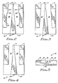
- Fig. 2 is a bottom plan view of an air bearing slider embodying the present invention,
- Fig. 3 is a bottom plan view of an alternative embodiment of an air bearing slider embodying the present invention,
- Fig. 4 is a bottom plan view of a further embodiment of an air bearing slider embodying the present invention,
- Fig. 5 is a view of the trailing end of the slider illustrated in Fig. 2, and
- Fig. 6 is a side elevation view of the sliders illustrated in Figs. 2, 3 and 4.
- With reference to Fig. 1, a magnetic disk storage system comprises a
magnetic head arm 17, and at least one magnetic head suspension assembly is attached tohead arm 17. In the embodiment shown, one magnetichead suspension assembly 13 is attached to the top of the head arm and another magnetichead suspension assembly 13 is attached to the bottom of thehead arm 17. Each suspension assembly supports at its end ahead slider 10, and eachhead slider 10 has one or more magnetic transducer means, generally called magnetic heads, disposed so that the transducing gap may be in transducing relation with the surfaces ofmagnetisable disks 21, only one of which is shown in the drawing. Electrical signals can be conducted from the magnetic heads to a computer host system for use in the host system.Head arm 17 is attached to aconventional actuator 19 such as a voice coil motor, for example, for accessing the magnetic heads to various tracks on themagnetisable disk 21. - The
slider 10 is preferably a small slider since reduction of the slider size has many advantages such as cost, greater volumetric efficiency and performance. However, as the slider size is reduced, the flying height tolerances resulting from the manufacturing tolerances increase. The most significant contributions to the increase in flying height tolerances are from the pitch and roll parameters. For example, when the width of the slider is reduced by one half, the contribution from the roll sensitive parameters to the flying height approximately doubles, and, when the length of the slider is reduced by one half, the contribution from the pitch sensitive parameters to the flying height increases by approximately five times. It is the goal of the small slider design to reduce the size of the slider to approximately one half the presently used size in both the length and width directions. There is described below a design that produces superior performance in terms of maintaining a predetermined flying height tolerance in a small slider format. - With reference to the Figures of the drawing, the air bearing surface (ABS) of the
magnetic head slider 10 is formed with twoside rails centre rail 16. The inner sides of theside rails centre rail 16 border onrecessed sections 18 that are formed by etching, ion milling, or other machining techniques, for example. Therecessed sections 18 extend from the leadingend 20 of the slider to the trailingend 22 of the slider. Amagnetic transducer 24, preferably of the thin film type, is bonded at the trailing end of thecentre rail 16 with its transducing gap flush with the rail surface. Bothside rails centre rail 16 all havetapered height sections 11 at their leading ends. - The
side rails end 20 of the slider and a relatively low pressure in the middle area of the slider. - In the embodiment shown in Fig. 2, each of the side rails includes a
wide section end 20 of the slider having substantially parallel sides and a flaredsection section narrow section side section narrow section - The embodiment shown in Fig. 3 has
side rails end 20 of the slider and narrowest at the trailing end of theside rail -
Centre rail 16 in each of the above arrangements comprises atapered section 11 at the leadingend 20 of the slider and a width which is small at the leading end and increases progressively toward thetrailing end 22 of the slider. Should any contaminants be present in the air bearing adjacent to theABS 15 ofslider 10, the shape of the centre rail causes the contaminants to be directed alongrecesses 18 so that they are moved away from thetransducer 24 at the trailing end of thecentre rail 16. - The configuration of the slider which is shown in the drawings and described above has different pressure zones. The pressure zones are formed when the
ABS 15 of the slider is positioned adjacent to amagnetisable recording surface 38 of magnetic disk 21 (Fig. 6) moving in the direction ofarrow 40 to provide load forces on the slider assembly that are balanced in such a manner that the desired flying characteristics for the slider can be achieved. The pressure components are combined so that theslider 10 flies at a desired pitch angle ϑ relative to the movingmagnetisable disk surface 38 with an attitude by which the trailing end ofslider 10, where the transducer is mounted, is closest to the disk surface and assured to be spaced at a flying height distance d from themagnetic recording medium 38. - The design approach to reduce the contribution to flying height tolerance from the pitch and roll sensitive parameters is accomplished, in the described embodiments, by having a larger load carried by the centre rail at the trailing end, which is also the minimum spacing location with respect to the disk because of the shorter side rails, in balanced equilibrium with the large load carried by the side rails near the leading end of the slider. The pressure from the side rails is high at the leading end of the slider due to the
taper sections 11 and the greater width at the leading end of the slider. The pressure from the side rails is progressively decreased and ceases to exist prior to reaching the trailing end of the slider. Thecentre rail 16 generates very little pressure at theleading end 20 of the slider, but the pressure from thecentre rail 16 progressively increases and is highest near the trailingend 22 of the slider. - The resulting combined pressure profile has high pressure near the leading
end 20 of theslider 10, a relatively low pressure in the middle of the slider, and a relatively high pressure near the trailingend 22 of the slider. This design approach ensures that the minimum spacing between the slider and the disk, on which recording performance and head/disk interface reliability depend, is very insensitive to roll parameters, thus slider width can be significantly reduced. Furthermore, the high air bearing pressure at the centre rail trailing end and the side rail leading ends ensures sufficiently high air bearing pitch and vertical stiffness, so that the length can also be significantly reduced. This design approach has-made possible the design of sliders with lengths significantly smaller than was otherwise possible.
Claims (6)
- A magnetic recording apparatus comprising:
a movable magnetisable recording medium (21) having a recording surface,
a magnetic transducer (24) and an air bearing slider (10) supporting said transducer,
head arm means (17) for supporting said air bearing slider with said magnetic transducer closely adjacent to the recording surface of said magnetisable recording medium, and
accessing means (19) for moving said head arm means relative to the recording surface of said magnetisable recording medium,
said air bearing slider having leading and trailing ends, an air bearing surface and side rails (12,14) disposed along the sides of said air bearing surface, said side rails being substantially coplanar and extending from the leading end of said slider towards the trailing end of said slider, and said side rails each having a tapered section (11) formed on the air bearing surface at said leading end, and each having a maximum width measured normal to the leading end to trailing end dimension of said slider which does not exceed the width of said side rails at said leading end of said slider,
characterised in that
each of said side rails (12,14) extends only part way to the trailing end of said slider,
and in that
said slider further comprises a centre rail (16) disposed along the central region of said air bearing surface, said centre rail being spaced from said side rails by recessed sections (18) which extend from said leading end to said trailing end of said slider, said centre rail having a tapered section at said leading end, and a width measured normal to the leading end to trailing end dimension of said slider which is smallest at said leading end and which is greatest at said trailing end of said slider,
whereby said rails (12,14,16) and said recessed sections (18) produce a combined pressure profile when said slider (10) is positioned adjacent said moving magnetisable recording medium (21), so that said slider assumes an orientation having a predetermined pitch angle and a predetermined spacing with respect to said moving magnetisable medium in which the minimum spacing between said slider and said magnetic medium occurs at the trailing end of said slider. - Apparatus as claimed in claim 1 characterised in that the ratio of the length of each side rails to the length of said slider is less than 0.9.
- Apparatus as claimed in either of the preceding claims characterised in that the ratio of the length of each side rails to the length of said slider is within the range of 0.5 to 0.8.
- Apparatus as claimed in any one of the preceding claims characterised in that each side rail comprises a first part (26,28) having a first predetermined width, as measured normal to the leading end to trailing end dimension of said slider, at said leading end of said side rail structure and a width that decreases to a second part (34,36) having a second predetermined width at a break point, said break point being located between said leading end and said trailing end of said side rail, wherein said width of said side rail does not exceed said second predetermined width between said break point and said trailing end of said side rail.
- Apparatus as claimed in Claim 4 characterised in that the parts of said side rail having said first and said second predetermined widths are connected by a flared section (30,32).
- Apparatus as claimed in Claim 5 characterised in that said parts of said side rail having said first and said second predetermined widths (26,28; 34,36) have sides that are substantially parallel.
Applications Claiming Priority (2)
| Application Number | Priority Date | Filing Date | Title |
|---|---|---|---|
| US07/250,686 US4894740A (en) | 1988-09-28 | 1988-09-28 | Magnetic head air bearing slider |
| US250686 | 1988-09-28 |
Publications (2)
| Publication Number | Publication Date |
|---|---|
| EP0361658A1 EP0361658A1 (en) | 1990-04-04 |
| EP0361658B1 true EP0361658B1 (en) | 1994-08-03 |
Family
ID=22948743
Family Applications (1)
| Application Number | Title | Priority Date | Filing Date |
|---|---|---|---|
| EP89307979A Expired - Lifetime EP0361658B1 (en) | 1988-09-28 | 1989-08-04 | Magnetic recording apparatus with magnetic head air bearing slider |
Country Status (10)
| Country | Link |
|---|---|
| US (1) | US4894740A (en) |
| EP (1) | EP0361658B1 (en) |
| JP (1) | JPH071619B2 (en) |
| KR (1) | KR920001267B1 (en) |
| CN (2) | CN1017840B (en) |
| AR (1) | AR243295A1 (en) |
| BR (1) | BR8904889A (en) |
| CA (1) | CA1311838C (en) |
| DE (1) | DE68917239T2 (en) |
| GB (1) | GB8912167D0 (en) |
Families Citing this family (83)
| Publication number | Priority date | Publication date | Assignee | Title |
|---|---|---|---|---|
| US5227212A (en) * | 1989-03-16 | 1993-07-13 | International Business Machines Corporation | Magnetic recording disk, magnetoresistive read head, inductive write head combination |
| US5097370A (en) * | 1989-03-17 | 1992-03-17 | Digital Equipment Corporation | Subambient pressure air bearing slider for disk drive |
| US5274518A (en) * | 1990-05-25 | 1993-12-28 | Seagate Technology, Inc. | Negative pressure air bearing slider having converging isolation channels |
| US5200868A (en) * | 1990-05-25 | 1993-04-06 | Seagate Technology, Inc. | Negative pressure air bearing slider having an air bearing surface trailing a negative pressure cavity |
| US5343343A (en) * | 1990-05-25 | 1994-08-30 | Seagate Technology, Inc. | Air bearing slider with relieved rail ends |
| US5218494A (en) * | 1990-05-25 | 1993-06-08 | Seagate Technology, Inc. | Negative pressure air bearing slider having isolation channels with edge step |
| US5196973A (en) * | 1990-05-25 | 1993-03-23 | Seagate Technology, Inc. | Negative pressure air bearing slider having isolation channels which terminate prior to trailing edge |
| JPH04228157A (en) * | 1990-07-13 | 1992-08-18 | Fujitsu Ltd | Magnetic head slider |
| JPH06501333A (en) * | 1990-09-14 | 1994-02-10 | ハッチンソン テクノロジー インコーポレイテッド | Improved inverted railhead suspension |
| US5461525A (en) * | 1990-09-14 | 1995-10-24 | Hutchinson Technology Incorporated | Load beam having areas of varying thickness in the spring region formed by varying numbers of lamina |
| US5198945A (en) * | 1990-11-09 | 1993-03-30 | Hutchinson Technology Incorporated | Magnetic head suspension |
| US5912788A (en) * | 1990-11-09 | 1999-06-15 | Hutchinson Technology Inc. | Flexure region for one-piece flexure-load beam structure |
| US5291359A (en) * | 1991-04-29 | 1994-03-01 | Hutchinson Technology Incorporated | Head suspension assembly including a flexure having rails arranged for interfacing with a head ramp |
| US5267109A (en) * | 1991-06-14 | 1993-11-30 | Seagate Technology, Inc. | Air bearing slider with relieved trailing edge |
| US5202803A (en) * | 1991-07-02 | 1993-04-13 | International Business Machines Corporation | Disk file with liquid film head-disk interface |
| US5200867A (en) * | 1991-07-02 | 1993-04-06 | International Business Machines Corporation | Transducer carrier for disk file with liquid film head-disk interface |
| AU646374B2 (en) * | 1991-07-02 | 1994-02-17 | International Business Machines Corporation | Disk file with liquid film head-disk interface |
| US5287235A (en) * | 1991-10-28 | 1994-02-15 | International Business Machines Corporation | Slider air bearing surface with angled rail configuration |
| FR2683369B1 (en) * | 1991-10-30 | 1993-12-24 | Commissariat A Energie Atomique | CATAMARAN FLIGHT SKATE WITH PERIPHERAL LOCKINGS. |
| DE69318445T2 (en) * | 1992-03-06 | 1998-09-03 | Read Rite Corp | Triple-air cushioned sliding body for magnetic head |
| US5473485A (en) * | 1992-03-06 | 1995-12-05 | Read-Rite Corporation | Tripad air bearing magnetic head slider |
| KR100227352B1 (en) * | 1992-03-06 | 1999-11-01 | 네펠라 다니엘 에이. | Tripad air bearing magnetic head slider |
| US5285337A (en) * | 1992-04-30 | 1994-02-08 | International Business Machines Corporation | Liquid-bearing data recording disk file with transducer carrier having support struts |
| US5267104A (en) * | 1992-04-30 | 1993-11-30 | International Business Machines Corporation | Liquid-bearing data recording disk file with transducer carrier having rear ski pad at the head-disk interface |
| US5452151A (en) * | 1992-05-29 | 1995-09-19 | J. Money & Associates, Inc. | Data access module |
| US5327310A (en) * | 1992-06-25 | 1994-07-05 | Read-Rite Corporation | Thin film contact recording head |
| US5345353A (en) * | 1992-09-21 | 1994-09-06 | International Business Machines Corporation | Step projection air bearing slider with improved stiction performance and wear resistance |
| EP0592697B1 (en) * | 1992-10-08 | 1998-07-08 | TDK Corporation | A method of maintaining a constant flying height of a magnetic head and a magnetic disk drive utilized therefor |
| US5438467A (en) * | 1992-10-28 | 1995-08-01 | International Business Machines Corporation | Negative pressure air bearing design |
| JPH06203515A (en) * | 1992-11-30 | 1994-07-22 | Read Rite Corp | Magnetic-head slider |
| US6084743A (en) | 1992-12-14 | 2000-07-04 | Maxtor Corporation | Magnetic recorder apparatus with reduced debris accumlation on the recorder head and slider |
| US5388017A (en) * | 1993-01-29 | 1995-02-07 | International Business Machines Corporation | Disk file with air-bearing slider having skids |
| US5353180A (en) * | 1993-03-01 | 1994-10-04 | Read-Rite Corporation | Air bearing magnetic slider with wishbone-shaped rails |
| JP3478556B2 (en) * | 1993-03-18 | 2003-12-15 | 松下電器産業株式会社 | Magnetic head slider |
| US6075683A (en) * | 1993-04-26 | 2000-06-13 | International Business Machines Corporation | Disk drive with passive multiple fly height slider and cooperative disk pattern |
| US5636086A (en) * | 1993-05-28 | 1997-06-03 | International Business Machines Corporation | Roll insensitive air bearing slider |
| US5396386A (en) * | 1993-05-28 | 1995-03-07 | International Business Machines Corporation | Roll insensitive air bearing slider |
| JPH0721717A (en) * | 1993-06-24 | 1995-01-24 | Internatl Business Mach Corp <Ibm> | Air-bearing-slider having no speed and skew dependency |
| US5424888A (en) * | 1993-06-24 | 1995-06-13 | International Business Machines Corp. | Speed independent, air bearing slider |
| JP2790011B2 (en) * | 1993-08-20 | 1998-08-27 | 日本電気株式会社 | Manufacturing method of floating head slider |
| US5406432A (en) * | 1993-10-07 | 1995-04-11 | Read-Rite Corporation | Air bearing magnetic head sliders with separate center rail segments |
| JPH07141813A (en) * | 1993-11-17 | 1995-06-02 | Sony Corp | Floating head slider and disk drive device |
| US5488524A (en) * | 1993-12-21 | 1996-01-30 | International Business Machines Corporation | Self adaptive head for semi-contact recording |
| KR0175255B1 (en) * | 1994-07-07 | 1999-04-15 | 김광호 | Magnetic recording head for hard disc drive |
| JPH0863925A (en) * | 1994-08-29 | 1996-03-08 | Nec Corp | Floating head slider and manufacture thereof |
| US5550692A (en) * | 1994-09-29 | 1996-08-27 | Seagate Technology, Inc. | Proximity recording air bearing slider design with waist offset |
| US6118635A (en) * | 1994-10-20 | 2000-09-12 | Hitachi, Ltd. | Magnetic storage apparatus having a head with sliding pads |
| JP3642821B2 (en) * | 1995-03-17 | 2005-04-27 | 富士通株式会社 | Magnetic head slider |
| US5898540A (en) * | 1995-05-25 | 1999-04-27 | Hitachi, Ltd | Magnetic head and slider configuration for contact recording having a plurality of tapered surfaces |
| US5661618A (en) * | 1995-12-11 | 1997-08-26 | International Business Machines Corporation | Magnetic recording device having a improved slider |
| US5729399A (en) * | 1995-12-13 | 1998-03-17 | International Business Machines Corporation | Contact start/stop disk drive with minimized head-disk wear in textured landing zone |
| US5774304A (en) * | 1996-01-16 | 1998-06-30 | Seagate Technology, Inc. | Disc head slider having center rail with asymmetric edge steps |
| US6292332B1 (en) | 1996-01-16 | 2001-09-18 | Seagate Technology Llc | Compliant air bearing slider with wide midpoint rails for reliable proximity recording |
| US5831791A (en) * | 1996-03-27 | 1998-11-03 | Headway Technologies, Inc. | Negative Pressure air bearing slider having transition region between positive and negative pressure regions |
| US5796551A (en) * | 1996-10-16 | 1998-08-18 | International Business Machines Corporation | Landing pads for air bearing sliders and method for making the same |
| WO1998021716A1 (en) * | 1996-11-13 | 1998-05-22 | Seagate Technology, Inc. | Disc head slider having surface discontinuities to minimize fly stiction |
| DE19782237T1 (en) * | 1997-01-15 | 1999-12-02 | Seagate Technology | Slider with side rails with rear edge incisions |
| JP3292296B2 (en) | 1997-03-25 | 2002-06-17 | ティーディーケイ株式会社 | Slider, head, head device, and recording / reproducing device |
| USD475716S1 (en) | 1997-03-25 | 2003-06-10 | Tdk Corporation | Combined slider and head for reading or writing information on a disk |
| US5963396A (en) * | 1997-04-02 | 1999-10-05 | Marburg Technology, Inc. | Glide head with an outside active rail |
| US6611401B1 (en) | 1997-04-02 | 2003-08-26 | Marburg Technology, Inc. | Glide head with a transverse contact rail |
| JP3237751B2 (en) * | 1997-04-11 | 2001-12-10 | ティーディーケイ株式会社 | Magnetic head |
| US5986850A (en) * | 1997-06-16 | 1999-11-16 | Seagate Technology, Inc. | Positive pressure optical slider having wide center rail |
| DE19782290T1 (en) | 1997-07-23 | 2000-07-06 | Seagate Technology | Otic positive pressure slider with side pads at the rear end |
| US5940249A (en) * | 1997-11-10 | 1999-08-17 | International Business Machines Corporation | Shielded air bearing slider |
| US6366429B1 (en) * | 1998-03-20 | 2002-04-02 | Seagate Technology Llc | Patterned and directional selective roughening of a slider air-bearing surface |
| US6477011B1 (en) | 1998-08-24 | 2002-11-05 | International Business Machines Corporation | Magnetic recording device having an improved slider |
| US6194360B1 (en) | 1998-12-22 | 2001-02-27 | International Business Machines Corporation | Magnetic recording device |
| US6428715B1 (en) | 1998-12-22 | 2002-08-06 | International Business Machines Corporation | Method for producing sliders |
| US6663817B1 (en) | 1999-03-26 | 2003-12-16 | Hitachi Global Storage Technologies Netherlands, B.V. | Method for manufacture of sliders |
| US6069770A (en) * | 1999-10-04 | 2000-05-30 | International Business Machines Corporation | Method for producing sliders |
| US6804878B1 (en) | 1999-12-21 | 2004-10-19 | Hitachi Global Storage Technologies Netherlands B.V. | Method of improving the reliability of magnetic head sensors by ion milling smoothing |
| US6423240B1 (en) | 2000-01-07 | 2002-07-23 | International Business Machines Corporation | Process to tune the slider trailing edge profile |
| US6710295B1 (en) * | 2000-06-15 | 2004-03-23 | Hitachi Global Storage Technologies Netherlands, B.V. | Slider curvature modification by substrate melting effect produced with a pulsed laser beam |
| US6680821B2 (en) | 2001-04-18 | 2004-01-20 | Hitachi Global Storage Technologies, The Netherlands B.V. | Slider air bearing surface having improved fly height profile characteristics |
| US6661607B2 (en) | 2001-05-09 | 2003-12-09 | Guzik Technical Enterprises | Method and apparatus for electromagnetic interference reduction in magnetic recording devices |
| US7289302B1 (en) | 2001-10-04 | 2007-10-30 | Maxtor Corporation | On slider inductors and capacitors to reduce electrostatic discharge damage |
| US6674611B2 (en) | 2002-01-04 | 2004-01-06 | Hitachi Global Storage Technologies, The Netherlands B.V. | Air bearing design producing steeper ramp profile near the laser texture zone |
| US7314404B2 (en) * | 2006-02-13 | 2008-01-01 | Komag, Inc. | Burnishing head |
| JP4927425B2 (en) * | 2006-03-23 | 2012-05-09 | 新科實業有限公司 | Suspension, head gimbal assembly and disk drive using the same |
| US7719795B2 (en) * | 2006-11-15 | 2010-05-18 | Western Digital (Fremont), Llc | Head having a transducer heater and an air bearing surface with a flow-diversion dam and pressure-relief trough disposed upstream of the transducer |
| US7869163B2 (en) | 2007-08-23 | 2011-01-11 | International Business Machines Corporation | Air bearing at opposite side of linear tape to support tape into contact with head slider |
| KR101294392B1 (en) * | 2008-09-19 | 2013-08-08 | 가부시키가이샤 알박 | Manufacturing method for magnetic recording medium |
Family Cites Families (8)
| Publication number | Priority date | Publication date | Assignee | Title |
|---|---|---|---|---|
| US3823416A (en) * | 1973-03-01 | 1974-07-09 | Ibm | Flying magnetic transducer assembly having three rails |
| JPS52138117A (en) * | 1976-05-14 | 1977-11-18 | Hitachi Ltd | Magnetic converter |
| JPS548514A (en) * | 1977-06-21 | 1979-01-22 | Nec Corp | Floating magnetic head |
| US4555739A (en) * | 1982-11-26 | 1985-11-26 | International Business Machines Corporation | Semi self-loading ferrite head |
| JPS61170922A (en) * | 1985-01-23 | 1986-08-01 | Fujitsu Ltd | Magnetic head slider |
| EP0218811B1 (en) * | 1985-07-19 | 1991-05-29 | Kabushiki Kaisha Toshiba | Magnetic head slider assembly |
| US4700248A (en) * | 1986-03-17 | 1987-10-13 | Polaroid Corporation | Magnetic head assembly with angled slots |
| US4734803A (en) * | 1986-03-20 | 1988-03-29 | International Business Machines | Magnetic head air bearing slider |
-
1988
- 1988-09-28 US US07/250,686 patent/US4894740A/en not_active Expired - Lifetime
-
1989
- 1989-05-26 GB GB898912167A patent/GB8912167D0/en active Pending
- 1989-06-20 CA CA000603325A patent/CA1311838C/en not_active Expired - Lifetime
- 1989-08-01 JP JP1198105A patent/JPH071619B2/en not_active Expired - Fee Related
- 1989-08-04 EP EP89307979A patent/EP0361658B1/en not_active Expired - Lifetime
- 1989-08-04 DE DE68917239T patent/DE68917239T2/en not_active Expired - Fee Related
- 1989-08-25 CN CN90110143A patent/CN1017840B/en not_active Expired
- 1989-08-25 CN CN89106616A patent/CN1015496B/en not_active Expired
- 1989-08-28 KR KR1019890012234A patent/KR920001267B1/en not_active Expired
- 1989-09-22 AR AR89314989A patent/AR243295A1/en active
- 1989-09-27 BR BR898904889A patent/BR8904889A/en not_active Application Discontinuation
Also Published As
| Publication number | Publication date |
|---|---|
| CN1017840B (en) | 1992-08-12 |
| KR900005426A (en) | 1990-04-14 |
| CN1041470A (en) | 1990-04-18 |
| EP0361658A1 (en) | 1990-04-04 |
| CA1311838C (en) | 1992-12-22 |
| DE68917239D1 (en) | 1994-09-08 |
| KR920001267B1 (en) | 1992-02-08 |
| AR243295A1 (en) | 1993-07-30 |
| GB8912167D0 (en) | 1989-07-12 |
| JPH02101688A (en) | 1990-04-13 |
| CN1015496B (en) | 1992-02-12 |
| US4894740A (en) | 1990-01-16 |
| CN1052567A (en) | 1991-06-26 |
| DE68917239T2 (en) | 1995-03-09 |
| JPH071619B2 (en) | 1995-01-11 |
| BR8904889A (en) | 1990-05-08 |
Similar Documents
| Publication | Publication Date | Title |
|---|---|---|
| CA1311838C (en) | Magnetic head air bearing slider | |
| EP0237752B1 (en) | An air bearing slider | |
| US5396386A (en) | Roll insensitive air bearing slider | |
| US6590746B2 (en) | Negative pressure air-lubricated bearing slider | |
| US5650893A (en) | Roll insensitive air bearing slider | |
| US5777825A (en) | Negative pressure step pad air bearing design and method for making the same | |
| US5796551A (en) | Landing pads for air bearing sliders and method for making the same | |
| US5870250A (en) | Method and apparatus for improving file capacity using different flying height profiles | |
| KR100288869B1 (en) | Design of a double etch step pad type air bearing with three etch depths | |
| US6128163A (en) | Disk drive including slider with recessed magneto-resistive transducer | |
| EP0576904A1 (en) | Thin film recording head | |
| US7515384B2 (en) | Method and apparatus for providing a three stepped air bearing having a funnel structure for controlling air flow to improve fly height performance | |
| US5978176A (en) | Magnetic head for a magnetic disk having a slider with indented portions for providing heat dissipation | |
| IE81026B1 (en) | Air bearing slider with offset crossbars to reduce roll | |
| US6421908B1 (en) | Method of making shallow etch air bearing surface features for optimized transducer spacing | |
| US20030218832A1 (en) | Magnetic head slider, support therefor and magnetic disk unit | |
| US5555145A (en) | Floating head slider with a magnetic head integrated therein | |
| US6243232B1 (en) | Magnetic head | |
| US6222703B1 (en) | Magnetic head for reading from and writing to a rotated magnetic disc in an elevated state produced by air flow and structure for supporting same | |
| EP0627732A1 (en) | Thin film transducer with reduced flying height | |
| US6141181A (en) | Magnetic disk apparatus with floating sliders having obliquely mounted rails | |
| US6400528B1 (en) | Magnetic head | |
| US7251107B2 (en) | Method and apparatus for providing an air bearing pad having improved roll angle sigma |
Legal Events
| Date | Code | Title | Description |
|---|---|---|---|
| PUAI | Public reference made under article 153(3) epc to a published international application that has entered the european phase |
Free format text: ORIGINAL CODE: 0009012 |
|
| AK | Designated contracting states |
Kind code of ref document: A1 Designated state(s): DE ES FR GB |
|
| 17P | Request for examination filed |
Effective date: 19900723 |
|
| 17Q | First examination report despatched |
Effective date: 19930506 |
|
| GRAA | (expected) grant |
Free format text: ORIGINAL CODE: 0009210 |
|
| AK | Designated contracting states |
Kind code of ref document: B1 Designated state(s): DE ES FR GB |
|
| PG25 | Lapsed in a contracting state [announced via postgrant information from national office to epo] |
Ref country code: ES Free format text: THE PATENT HAS BEEN ANNULLED BY A DECISION OF A NATIONAL AUTHORITY Effective date: 19940803 |
|
| REF | Corresponds to: |
Ref document number: 68917239 Country of ref document: DE Date of ref document: 19940908 |
|
| ET | Fr: translation filed | ||
| PLBE | No opposition filed within time limit |
Free format text: ORIGINAL CODE: 0009261 |
|
| STAA | Information on the status of an ep patent application or granted ep patent |
Free format text: STATUS: NO OPPOSITION FILED WITHIN TIME LIMIT |
|
| 26N | No opposition filed | ||
| PGFP | Annual fee paid to national office [announced via postgrant information from national office to epo] |
Ref country code: FR Payment date: 19990817 Year of fee payment: 11 |
|
| PG25 | Lapsed in a contracting state [announced via postgrant information from national office to epo] |
Ref country code: FR Free format text: LAPSE BECAUSE OF NON-PAYMENT OF DUE FEES Effective date: 20010430 |
|
| REG | Reference to a national code |
Ref country code: FR Ref legal event code: ST |
|
| PGFP | Annual fee paid to national office [announced via postgrant information from national office to epo] |
Ref country code: DE Payment date: 20010821 Year of fee payment: 13 |
|
| REG | Reference to a national code |
Ref country code: GB Ref legal event code: IF02 |
|
| PG25 | Lapsed in a contracting state [announced via postgrant information from national office to epo] |
Ref country code: DE Free format text: LAPSE BECAUSE OF NON-PAYMENT OF DUE FEES Effective date: 20030301 |
|
| REG | Reference to a national code |
Ref country code: GB Ref legal event code: 732E |
|
| PGFP | Annual fee paid to national office [announced via postgrant information from national office to epo] |
Ref country code: GB Payment date: 20080724 Year of fee payment: 20 |
|
| REG | Reference to a national code |
Ref country code: GB Ref legal event code: PE20 Expiry date: 20090803 |
|
| PG25 | Lapsed in a contracting state [announced via postgrant information from national office to epo] |
Ref country code: GB Free format text: LAPSE BECAUSE OF EXPIRATION OF PROTECTION Effective date: 20090803 |