EP0358477B1 - Improved tape dispenser - Google Patents
Improved tape dispenser Download PDFInfo
- Publication number
- EP0358477B1 EP0358477B1 EP89309014A EP89309014A EP0358477B1 EP 0358477 B1 EP0358477 B1 EP 0358477B1 EP 89309014 A EP89309014 A EP 89309014A EP 89309014 A EP89309014 A EP 89309014A EP 0358477 B1 EP0358477 B1 EP 0358477B1
- Authority
- EP
- European Patent Office
- Prior art keywords
- tape
- spool
- trailing end
- leading end
- obstacle
- Prior art date
- Legal status (The legal status is an assumption and is not a legal conclusion. Google has not performed a legal analysis and makes no representation as to the accuracy of the status listed.)
- Expired - Lifetime
Links
- 230000004044 response Effects 0.000 claims abstract description 8
- 238000000034 method Methods 0.000 claims description 13
- 230000003014 reinforcing effect Effects 0.000 claims description 7
- 230000007704 transition Effects 0.000 claims 2
- 230000007246 mechanism Effects 0.000 abstract description 3
- 238000004806 packaging method and process Methods 0.000 description 13
- 230000010355 oscillation Effects 0.000 description 3
- 230000001133 acceleration Effects 0.000 description 2
- 239000002390 adhesive tape Substances 0.000 description 2
- 230000000873 masking effect Effects 0.000 description 2
- 230000009471 action Effects 0.000 description 1
- 230000000712 assembly Effects 0.000 description 1
- 238000000429 assembly Methods 0.000 description 1
- 230000008859 change Effects 0.000 description 1
- 238000010276 construction Methods 0.000 description 1
- 230000007423 decrease Effects 0.000 description 1
- 230000003247 decreasing effect Effects 0.000 description 1
- 230000003467 diminishing effect Effects 0.000 description 1
- 230000008713 feedback mechanism Effects 0.000 description 1
- 239000012943 hotmelt Substances 0.000 description 1
- 230000006872 improvement Effects 0.000 description 1
- 239000000463 material Substances 0.000 description 1
- 230000004048 modification Effects 0.000 description 1
- 238000012986 modification Methods 0.000 description 1
- 230000008569 process Effects 0.000 description 1
- 230000009467 reduction Effects 0.000 description 1
- 238000009987 spinning Methods 0.000 description 1
- 230000003068 static effect Effects 0.000 description 1
Images



Classifications
-
- B—PERFORMING OPERATIONS; TRANSPORTING
- B65—CONVEYING; PACKING; STORING; HANDLING THIN OR FILAMENTARY MATERIAL
- B65H—HANDLING THIN OR FILAMENTARY MATERIAL, e.g. SHEETS, WEBS, CABLES
- B65H19/00—Changing the web roll
- B65H19/10—Changing the web roll in unwinding mechanisms or in connection with unwinding operations
- B65H19/12—Lifting, transporting, or inserting the web roll; Removing empty core
- B65H19/123—Lifting, transporting, or inserting the web roll; Removing empty core with cantilever supporting arrangements
-
- B—PERFORMING OPERATIONS; TRANSPORTING
- B65—CONVEYING; PACKING; STORING; HANDLING THIN OR FILAMENTARY MATERIAL
- B65H—HANDLING THIN OR FILAMENTARY MATERIAL, e.g. SHEETS, WEBS, CABLES
- B65H2301/00—Handling processes for sheets or webs
- B65H2301/40—Type of handling process
- B65H2301/46—Splicing
- B65H2301/463—Splicing splicing means, i.e. means by which a web end is bound to another web end
- B65H2301/46325—Separate element, e.g. clip
-
- B—PERFORMING OPERATIONS; TRANSPORTING
- B65—CONVEYING; PACKING; STORING; HANDLING THIN OR FILAMENTARY MATERIAL
- B65H—HANDLING THIN OR FILAMENTARY MATERIAL, e.g. SHEETS, WEBS, CABLES
- B65H2405/00—Parts for holding the handled material
- B65H2405/40—Holders, supports for rolls
- B65H2405/42—Supports for rolls fully removable from the handling machine
- B65H2405/422—Trolley, cart, i.e. support movable on floor
-
- B—PERFORMING OPERATIONS; TRANSPORTING
- B65—CONVEYING; PACKING; STORING; HANDLING THIN OR FILAMENTARY MATERIAL
- B65H—HANDLING THIN OR FILAMENTARY MATERIAL, e.g. SHEETS, WEBS, CABLES
- B65H2701/00—Handled material; Storage means
- B65H2701/30—Handled filamentary material
- B65H2701/37—Tapes
- B65H2701/377—Adhesive tape
Definitions
- the present invention relates to automatic tape dispensing systems, and more particularly to apparatuses for splicing and tensioning tapes in such systems.
- Modern consumer and industrial packaging often includes reinforcing tapes or tear tapes as part of their construction.
- Various tape dispensers have been devised to dispense such tapes into corrugator and packaging equipment. However, all have certain drawbacks.
- some tape dispensing systems rely on a human operator to stand at the ready and manually splice the tapes together.
- the operator loops the leading end of a replacement spool of tape about the free running tape on the first spool.
- the corrugator or packaging equipment is slowed to about one third of its normal speed and the operator cinches the loop onto the free running tape to form a splice knot.
- the second spool is manually spins the second spool to overcome its static inertia so that the machine can draw tape therefrom.
- a tape dispensing apparatus comprising: first and second spools of tape, the tape on each of said spools having a leading end and a trailing end; and an element on or near the trailing end of the first tape that cooperates with an element on the leading end of the second tape to make said second spool of tape self splicing to the first so that when the first spool becomes depleted of tape, the second spool can begin immediately dispensing tape in its stead.
- a method of dispensing reinforcing or tear tape characterised by the steps of: providing a roll of a first tape having on or near a trailing end thereof an obstacle extending thereacross; providing a roll of a second tape having on a leading end thereof a string extending thereacross, said string having first and second ends; dispensing tape from the first roll and while so doing, tying the two ends of the string together to form a closed loop around the first tape; wherein when the first roll of tape is exhausted, the loop tied around the first tape will catch the obstacle extending thereacross, thereby linking the trailing end of the first tape to the leading end of the second tape and causing tape to be dispensed from the second roll.
- a spool of reinforcing or tear tape from which tape can be dispensed comprising a rolled length of tape having on a leading end thereof means for forming a loop and having on or near a trailing end thereof an obstacle extending across and beyond the width of the tape.
- one tape is provided near its trailing end with a pin extending thereacross.
- the second tape is provided at its leading end with a loop sized so that the pin cannot pass therethrough. When the pin engages the loop, the tapes become linked, causing the trailing end of the first tape to pull the leading end of the second tape into the packaging equipment.
- the second spool of tape may be stationary when the splice is made.
- the tape path is provided with a movable roller guide.
- this roller guide moves against the force of a spring and acts to shorten the tape path when the tension in the tape increases.
- the shortened tape path provides the packaging equipment with the tape it needs without requiring the second spool to contemporaneously dispense a corresponding length.
- the movable roller returns under the influence of the spring to its initial position.
- An active brake assembly prevents the spool from unduly accelerating in response to this spring-driven lengthening of the tape path by the movable roller.
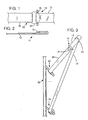
- Figure 1 is an illustration showing the splice formed by cooperation between a pin on the trailing end of a first tape with a loop on the leading end of a second tape.
- Fig. 2 is an illustration showing how the pin component is affixed to the tape end.
- Fig. 3 is an illustration showing a detachable tail on the trailing end of the first tape to maintain proper orientation of the splice.
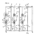
- Fig. 4 is a front view of a tape dispensing apparatus employing the tension control system of the present invention.
- Fig. 5 is a section taken on line 5-5 of Fig. 4.
- Fig. 6 is a view taken on line 6-6 of Fig. 5.
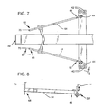
- Fig. 7 is a section taken on line 7-7 of Fig. 4.
- Fig. 8 is a view taken on line 8-8 of Fig. 7.
- Fig. 9 shows a brake band assembly used with the tension control system of Fig. 4.
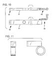
- Fig. 10 shows a lever used with the tension control system of Fig. 4.
- Fig. 11 shows a brake band bracket used with the tension control system of Fig. 4.
- Fig. 12 is a view showing portion of the tension control system of Fig. 4.
- Fig. 13 is a view showing another portion of the tension control system of Fig. 4.
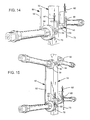
- Fig. 14 is a view showing the brake band and the spindles in the tension control system of Fig. 4.
- Fig. 15 is another view showing the brake band and the spindles in the tension control system of Fig. 4.
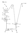
- Fig. 16 is a schematic illustration of the tension control system of Fig. 4.
- each tape is provided with end elements which cooperate with end elements on other tapes to make the tapes self- splicing.
- a first tape 12 is provided at its trailing end 14 with a pin end element 16.
- a second tape 18 is provided at its leading end 20 with a loop element 22. When the pin 16 engages the loop 22, the tapes become linked, causing the trailing end of the first tape to pull the leading end of the second tape into the machine.
- End elements 16 and 22 can be attached to the tapes in a variety of ways. Illustrated in Fig. 2 is a technique applicable with adhesive tapes, such as hot melt tapes, wherein the end element (here a pin 16) is placed on the tape and the tape looped back and adhered to itself. The loop element is affixed similarly.
- adhesive tapes such as hot melt tapes
- Fig. 3 shows the relationship of the two tapes just before the first spool of tape 24 becomes depleted. It will be recognized that some means must be provided for positioning loop 22 around the first tape 12. In the illustrated embodiment, this is achieved by forming end element 16 of reinforced string and tying it in a loop around the first tape. Other techniques could, of course, be used.
- the trailing end 14 of tape 12 comes off spool 24, it would normally be free to twist and turn. Such movement, however, may result in the tape being introduced into the machine wrong side down.
- the second tape that followed it would likewise be misoriented.
- the trailing end of the first tape 12 is desirably provided with a tail segment 26 affixed to the spool.
- the tail segment 26 has a length sufficient so that the second tape is linked to the trailing end of the first tape, in the proper orientation, before the end of the tail segment is reached.
- the tail segment 26 is detachably connected to the trailing end of the first tape 12 by means such as masking tape 27.
- the other end of the tail segment is securely affixed to the spool 24.
- the tail segment need not be detachable as shown. Instead, it can be securely affixed to the first tape and not connected to the spool. When the end of the tail segment comes free of the spool, it is introduced into the machine and applied just as with any other tape.
- a dispensing apparatus 30 with which the above splicing technique can be employed comprises a frame 32 on which are mounted two spools 24, 34 of tape. Tape is routed from one of these spools over a fixed roller 36 and down to a tensioning roller 38. Tensioning roller 38 is mounted on a block 40 that rides on slider rods 42. The block 40 is pulled downwardly by a spring 44 and upwardly by tension in the tape. (In the illustrated embodiment, the spring 44 is a rubber hose, as is visible in Fig. 12. In other embodiments, other mechanisms could of course be used, such as a hydraulic cylinder, etc.) The tape continues from tensioning roller 38 up over another fixed roller 46 and on into the corrugator equipment.
- Brake assembly 50 comprises a brake band 52 which extends about portions of the spindles 54, 56 on which the spools 24, 34 ride and acts to retard their rotation.
- the upper end 58 of the brake band 52 is stationary, affixed to the frame 32.
- the lower end 60 is connected to a spring 62 which is connected at its other end to the frame 32.
- the spring 62 tensions the brake band 52 and establishes a quiescent braking force on spools 24 and 34.
- the apparatus is provided with means for changing this braking force in response to changes in tape tension.
- tape tension When tape tension is low (i.e when the spool is providing tape faster than is required by the corrugator), it is desirable to apply an increased braking force to the spool to retard its dispensing of tape. Conversely, when the tape tension is high, it is desirable to apply a decreased braking force so that the dispensing of tape can be accelerated.
- one physical indicator of tape tension is the position of tensioning roller 38.
- the roller When tape tension is high, the roller is elevated. When tape tension is low, the roller assumes a lower position. This motion is advantageously used in the present invention to control the braking force applied to the spools.
- a lever 64 is pivotally mounted on the frame 32 and extends under the tensioning roller 38 and the braking assembly 50.
- spring 44 pulls upwardly on a first end 66 of the lever, causing the second end 68 of the lever to move downwardly.
- This movement is coupled to the brake assembly 50 by a member 70 which pulls against brake spring 62, thereby reducing the tension in the brake band and causes a corresponding reduction in the braking force.
- the first end 66 of the lever moves downwardly, moving the second end upwardly. This motion permits brake spring 62 to reapply more tensioning force to the brake band 52, thereby causing a corresponding increase in the braking force.
- the present invention employs a feedback mechanism that senses the tension in the tape and automatically adjusts the braking force in response thereto.
- the brake band 52 extends 180 degrees about the lower spindle 56, but a lesser distance about the upper spindle 54. This reflects the fact that the weight of the brake band 52 hanging down from the upper spindle applies a tensioning force to the brake band on the upper spindle that is not present on the lower spindle. It is desirable that the braking forces applied to the two spindles be matched, although this is not a requirement of the invention.
- Figs. 4-6 and 12-15 show a tape dispensing apparatus that incorporates six of the assemblies shown in Fig. 16.
Landscapes
- Controlling Rewinding, Feeding, Winding, Or Abnormalities Of Webs (AREA)
- Registering, Tensioning, Guiding Webs, And Rollers Therefor (AREA)
- Coating Apparatus (AREA)
- Auxiliary Devices For And Details Of Packaging Control (AREA)
- Replacement Of Web Rolls (AREA)
- Power Steering Mechanism (AREA)
- Tyre Moulding (AREA)
- Basic Packing Technique (AREA)
Abstract
Description
- The present invention relates to automatic tape dispensing systems, and more particularly to apparatuses for splicing and tensioning tapes in such systems.
- Modern consumer and industrial packaging often includes reinforcing tapes or tear tapes as part of their construction. Various tape dispensers have been devised to dispense such tapes into corrugator and packaging equipment. However, all have certain drawbacks.
- One of the principal drawbacks of the prior art systems is in their techniques for changing from one spool of tape to another when the first spool becomes depleted. Many systems require that the packaging line be halted while a new spool of tape is installed and threaded through the appropriate tape guides. This interruption is intolerable in complex packaging lines which rely, for their cost effectiveness, on continuous, uninterrupted operation.
- To partially alleviate the interruption problem, some tape dispensing systems rely on a human operator to stand at the ready and manually splice the tapes together. The operator loops the leading end of a replacement spool of tape about the free running tape on the first spool. When the first spool is nearly depleted, the corrugator or packaging equipment is slowed to about one third of its normal speed and the operator cinches the loop onto the free running tape to form a splice knot. At the same instant he manually spins the second spool to overcome its static inertia so that the machine can draw tape therefrom.
- This approach, although an improvement, has several problems. One is that it requires a skilled operator to monitor the tape spools and be ready to tie the splicing knot at the critical instant. Another problem is that it requires the packaging equipment be slowed from its usual speed. Still another problem is that, even if the splice is successfully made (and often it is not), the operator's manual acceleration of the second spool may not be sufficient to prevent the tape from breaking when the packaging line suddenly starts pulling several hundred of feet of tape per minute from the spool. A tape break, of course, requires that the packaging line be stopped, the very problem that was sought to be avoided. Yet another problem is that some slack may be momentarily introduced into the second tape by the operator's manual spinning of the spool. This slack permits the tape to change its orientation and may result, for example, in an adhesive tape being applied to the packaging wrong side down.
- Accordingly, a need remains for an improved technique for splicing from one spool of tape to another in an automatic packaging line so that the packaging line can reliably operate without interruption.
- It is an object of the present invention to fulfil this need.
- According to one aspect of the present invention there is provided a tape dispensing apparatus, comprising:
first and second spools of tape, the tape on each of said spools having a leading end and a trailing end; and
an element on or near the trailing end of the first tape that cooperates with an element on the leading end of the second tape to make said second spool of tape self splicing to the first so that when the first spool becomes depleted of tape, the second spool can begin immediately dispensing tape in its stead. - According to another aspect of the invention, there is provided a method of dispensing reinforcing or tear tape, characterised by the steps of:
providing a roll of a first tape having on or near a trailing end thereof an obstacle extending thereacross;
providing a roll of a second tape having on a leading end thereof a string extending thereacross, said string having first and second ends;
dispensing tape from the first roll and while so doing, tying the two ends of the string together to form a closed loop around the first tape;
wherein when the first roll of tape is exhausted, the loop tied around the first tape will catch the obstacle extending thereacross, thereby linking the trailing end of the first tape to the leading end of the second tape and causing tape to be dispensed from the second roll. - According to a further aspect of the invention, there is provided a spool of reinforcing or tear tape from which tape can be dispensed, comprising a rolled length of tape having on a leading end thereof means for forming a loop and having on or near a trailing end thereof an obstacle extending across and beyond the width of the tape.
- In a preferred embodiment, one tape is provided near its trailing end with a pin extending thereacross. The second tape is provided at its leading end with a loop sized so that the pin cannot pass therethrough. When the pin engages the loop, the tapes become linked, causing the trailing end of the first tape to pull the leading end of the second tape into the packaging equipment.
- The second spool of tape may be stationary when the splice is made. To prevent the tape from breaking under the strain of instantaneous acceleration, the tape path is provided with a movable roller guide. In one embodiment, this roller guide moves against the force of a spring and acts to shorten the tape path when the tension in the tape increases. The shortened tape path provides the packaging equipment with the tape it needs without requiring the second spool to contemporaneously dispense a corresponding length. As the new spool of tape comes up to speed, the movable roller returns under the influence of the spring to its initial position. An active brake assembly prevents the spool from unduly accelerating in response to this spring-driven lengthening of the tape path by the movable roller. Thus, the tension and orientation of the tapes are controlled during a splicing operation so that the spliced tape is not broken nor applied with the wrong orientation.
- An embodiment of the present invention is described below by way of example, with reference to the accompanying drawings, wherein:-
- Figure 1 is an illustration showing the splice formed by cooperation between a pin on the trailing end of a first tape with a loop on the leading end of a second tape.
- Fig. 2 is an illustration showing how the pin component is affixed to the tape end.
- Fig. 3 is an illustration showing a detachable tail on the trailing end of the first tape to maintain proper orientation of the splice.
- Fig. 4 is a front view of a tape dispensing apparatus employing the tension control system of the present invention.
- Fig. 5 is a section taken on line 5-5 of Fig. 4.
- Fig. 6 is a view taken on line 6-6 of Fig. 5.
- Fig. 7 is a section taken on line 7-7 of Fig. 4.
- Fig. 8 is a view taken on line 8-8 of Fig. 7.
- Fig. 9 shows a brake band assembly used with the tension control system of Fig. 4.
- Fig. 10 shows a lever used with the tension control system of Fig. 4.
- Fig. 11 shows a brake band bracket used with the tension control system of Fig. 4.
- Fig. 12 is a view showing portion of the tension control system of Fig. 4.
- Fig. 13 is a view showing another portion of the tension control system of Fig. 4.
- Fig. 14 is a view showing the brake band and the spindles in the tension control system of Fig. 4.
- Fig. 15 is another view showing the brake band and the spindles in the tension control system of Fig. 4.
- Fig. 16 is a schematic illustration of the tension control system of Fig. 4.
- Referring first to Fig. 1, each tape is provided with end elements which cooperate with end elements on other tapes to make the tapes self- splicing. In Fig. 1, a
first tape 12 is provided at itstrailing end 14 with apin end element 16. Asecond tape 18 is provided at its leadingend 20 with aloop element 22. When thepin 16 engages theloop 22, the tapes become linked, causing the trailing end of the first tape to pull the leading end of the second tape into the machine. -
End elements - Fig. 3 shows the relationship of the two tapes just before the first spool of
tape 24 becomes depleted. It will be recognized that some means must be provided forpositioning loop 22 around thefirst tape 12. In the illustrated embodiment, this is achieved by formingend element 16 of reinforced string and tying it in a loop around the first tape. Other techniques could, of course, be used. - When the trailing
end 14 oftape 12 comes offspool 24, it would normally be free to twist and turn. Such movement, however, may result in the tape being introduced into the machine wrong side down. The second tape that followed it would likewise be misoriented. To avoid this problem, the trailing end of thefirst tape 12 is desirably provided with atail segment 26 affixed to the spool. Thetail segment 26 has a length sufficient so that the second tape is linked to the trailing end of the first tape, in the proper orientation, before the end of the tail segment is reached. - In the embodiment shown in Fig. 3, the
tail segment 26 is detachably connected to the trailing end of thefirst tape 12 by means such as maskingtape 27. The other end of the tail segment is securely affixed to thespool 24. When the first tape draws the tail segment tight, the masking tape joint is pulled free, leaving the tail segment dangling from the spool and leaving the pin/loop splice free to travel into the machine. - In other embodiments, the tail segment need not be detachable as shown. Instead, it can be securely affixed to the first tape and not connected to the spool. When the end of the tail segment comes free of the spool, it is introduced into the machine and applied just as with any other tape.
- Referring now to Figs. 4-16, a dispensing
apparatus 30 with which the above splicing technique can be employed comprises aframe 32 on which are mounted twospools roller 36 and down to atensioning roller 38. Tensioningroller 38 is mounted on ablock 40 that rides onslider rods 42. Theblock 40 is pulled downwardly by aspring 44 and upwardly by tension in the tape. (In the illustrated embodiment, thespring 44 is a rubber hose, as is visible in Fig. 12. In other embodiments, other mechanisms could of course be used, such as a hydraulic cylinder, etc.) The tape continues from tensioningroller 38 up over another fixedroller 46 and on into the corrugator equipment. - Referring now particularly to Fig. 16, it will be recognized that when the
first spool 24 becomes depleted of tape, the above-described splicing technique will suddenly bring the second spool 34 (which had previously been stationary) into action. Since the second spool cannot immediately supply tape at the rate required by the corrugator (typically 600 feet per minute), the tension in the tape suddenly increases. The increased tension causesroller 38 to move upwardly against the force ofspring 44. This movement serves to shorten the tape path, thereby providing tape to the corrugator without requiring the second spool to dispense a corresponding length contemporaneously. - After the
second spool 34 accelerates to the required speed, the tension in the tape decreases. This permits theroller 38 to be pulled downwardly byspring 44. This movement, however, lengthens the tape path, momentarily pulling tape from the second spool at a rate greater than is required by the corrugator. This momentary oversupply of tape introduces slack into the system which diminishes the force pulling tape fromspool 34, permitting it to slow down. When the slack is used up, the spool is no longer operating at the requisite speed and a tension spike occurs when the system again tries to draw tape from the spool faster than it is immediately able to supply it. This in turn causes thetensioning roller 38 to move upwardly againstspring 44. The process repeats. The net result is a diminishing series of oscillations in the system, with the tape alternately going slack and too tight until equilibrium is finally established. During the slack intervals, the tape may become misoriented (i.e. wrong side down) or may even jump the rollers. - (Another way of conceptualizing this oscillation phenomenon is that
spring 44 absorbs energy applied by the corrugator when the second spool is started and stores it as spring tension. After the second spool accelerates to full operating speed, the spring releases that stored energy back to the system. This released energy is absorbed by the second spool and is stored in the form of a rotational speed higher than is required by the system. This generates an oversupply of free tape so that the pulling force exerted by the corrugator is no longer applied to the spool. The spool slows while the slack is taken up. When the slack is exhausted, the corrugator again exerts a tension spike against the spool (unless the spool is at exactly the speed required by the corrugator). This new tension spike again introduces energy intospring 44 and the cycle repeats). - To overcome this problem, the
apparatus 30 is provided with adynamic brake assembly 50.Brake assembly 50 comprises abrake band 52 which extends about portions of thespindles spools upper end 58 of thebrake band 52 is stationary, affixed to theframe 32. Thelower end 60 is connected to aspring 62 which is connected at its other end to theframe 32. Thespring 62 tensions thebrake band 52 and establishes a quiescent braking force onspools - When tape tension is low (i.e when the spool is providing tape faster than is required by the corrugator), it is desirable to apply an increased braking force to the spool to retard its dispensing of tape. Conversely, when the tape tension is high, it is desirable to apply a decreased braking force so that the dispensing of tape can be accelerated.
- In the illustrated embodiment, one physical indicator of tape tension is the position of tensioning
roller 38. When tape tension is high, the roller is elevated. When tape tension is low, the roller assumes a lower position. This motion is advantageously used in the present invention to control the braking force applied to the spools. - As shown in Fig. 16, a
lever 64 is pivotally mounted on theframe 32 and extends under the tensioningroller 38 and thebraking assembly 50. When tape tension is high,spring 44 pulls upwardly on afirst end 66 of the lever, causing thesecond end 68 of the lever to move downwardly. This movement is coupled to thebrake assembly 50 by amember 70 which pulls againstbrake spring 62, thereby reducing the tension in the brake band and causes a corresponding reduction in the braking force. Conversely, when the tape tension is lowered, thefirst end 66 of the lever moves downwardly, moving the second end upwardly. This motion permitsbrake spring 62 to reapply more tensioning force to thebrake band 52, thereby causing a corresponding increase in the braking force. - From the foregoing, it will be recognized that the present invention employs a feedback mechanism that senses the tension in the tape and automatically adjusts the braking force in response thereto.
- It will be noted that the
brake band 52 extends 180 degrees about thelower spindle 56, but a lesser distance about theupper spindle 54. This reflects the fact that the weight of thebrake band 52 hanging down from the upper spindle applies a tensioning force to the brake band on the upper spindle that is not present on the lower spindle. It is desirable that the braking forces applied to the two spindles be matched, although this is not a requirement of the invention. - Figs. 4-6 and 12-15 show a tape dispensing apparatus that incorporates six of the assemblies shown in Fig. 16.
- Having described and illustrated the principles of our invention with reference to a preferred embodiment, it will be apparent to those having skill in the art that the invention can be modified in arrangement and detail without departing from such principles. For example, while a braking assembly has been shown for quickly dampening undesirable oscillations in the system, in other embodiments, a variety of other techniques can be used to absorb the excess energy. In still other embodiments, the replacement spool is accelerated in response to electrical or mechanical sensors that indicate that the initial spool is about to be depleted.
- In view of these and the wide range of other embodiments to which the concepts of the present invention can be applied, it should be recognized that the foregoing description is illustrative only and is not to be construed as limiting the scope of the invention. Instead, we claim as our invention all such modifications as may come within the scope of the following claims and equivalents thereof.
- The features disclosed in the foregoing description, in the following claims and/or in the accompanying drawings may, both separately and in any combination thereof, be material for realising the invention in diverse forms thereof.
Claims (18)
first and second spools of tape, (24, 34) the tape on each of said spools having a leading end and a trailing end; and
an element (16) on or near the trailing end (14) of the first tape (12) that cooperates with an element (22) on the leading end (20) of the second tape (18) to make said second spool of tape self splicing to the first so that when the first spool becomes depleted of tape, the second spool can begin immediately dispensing tape in its stead.
the element on the leading end of the second tape defines a passageway through which the obstacle cannot pass.
the element on the trailing end of the first tape (12) comprises a pin (16) extending transversely across the tape, the pin having a length longer than the width of the tape; and
the element on the leading end of the second tape (18) comprises means (22) for forming a loop around the first tape in which the pin can engage.
the brake means includes a movable control member (70) for controlling the braking force applied to the spools;
the dispensing apparatus includes;
a tape guide member (38, 40) movable in response to tension in the tape being dispensed; and
a mechanical linkage (44, 64) coupled to the movable guide member (38, 40) and to the movable control member (70) for controlling the braking force in response to the position of the guide member.
providing a roll of a first tape (12) having on or near a trailing end (14) thereof an obstacle (16) extending thereacross;
providing a roll of a second tape (18) having on a leading end (20) thereof a string (22) extending thereacross, said string having first and second ends;
dispensing tape from the first roll and while so doing, tying the two ends of the string (22) together to form a closed loop around the first tape (12);
wherein when the first roll of tape is exhausted, the loop (220) tied around the first tape will catch the obstacle (16) extending thereacross, thereby linking the trailing end of the first tape to the leading end of the second tape and causing tape to be dispensed from the second roll.
Priority Applications (1)
| Application Number | Priority Date | Filing Date | Title |
|---|---|---|---|
| AT89309014T ATE76848T1 (en) | 1988-09-07 | 1989-09-06 | STRIP DISPENSER. |
Applications Claiming Priority (2)
| Application Number | Priority Date | Filing Date | Title |
|---|---|---|---|
| US241418 | 1988-09-07 | ||
| US07/241,418 US4917327A (en) | 1988-09-07 | 1988-09-07 | Tape dispenser |
Publications (3)
| Publication Number | Publication Date |
|---|---|
| EP0358477A2 EP0358477A2 (en) | 1990-03-14 |
| EP0358477A3 EP0358477A3 (en) | 1990-07-18 |
| EP0358477B1 true EP0358477B1 (en) | 1992-06-03 |
Family
ID=22910612
Family Applications (1)
| Application Number | Title | Priority Date | Filing Date |
|---|---|---|---|
| EP89309014A Expired - Lifetime EP0358477B1 (en) | 1988-09-07 | 1989-09-06 | Improved tape dispenser |
Country Status (7)
| Country | Link |
|---|---|
| US (1) | US4917327A (en) |
| EP (1) | EP0358477B1 (en) |
| JP (1) | JP2718776B2 (en) |
| AT (1) | ATE76848T1 (en) |
| CA (1) | CA1280097C (en) |
| DE (1) | DE68901699T2 (en) |
| ES (1) | ES2031690T3 (en) |
Cited By (2)
| Publication number | Priority date | Publication date | Assignee | Title |
|---|---|---|---|---|
| CN102774678A (en) * | 2012-07-23 | 2012-11-14 | 苏州迪盛织造整理有限公司 | Cloth roller unwinding stabilization device for cloth inspection machine |
| CN103502124A (en) * | 2011-03-04 | 2014-01-08 | 阿达利斯公司 | Ribbon engagement system and method |
Families Citing this family (22)
| Publication number | Priority date | Publication date | Assignee | Title |
|---|---|---|---|---|
| JPH08510707A (en) * | 1993-05-26 | 1996-11-12 | ミネソタ・マイニング・アンド・マニュファクチュアリング・カンパニー | Tape feeding and pasting system with tape joining mechanism |
| US6325324B1 (en) * | 1999-09-16 | 2001-12-04 | Industrial Adhesives, Inc. | Tape splicing system |
| US6893528B2 (en) | 2000-11-01 | 2005-05-17 | Adalis Corporation | Web material advance system for web material applicator |
| WO2002036337A1 (en) | 2000-11-01 | 2002-05-10 | Linear Products Inc. | Splicing system affording a continuous web material supply for an applicator |
| US6622959B2 (en) * | 2001-08-31 | 2003-09-23 | Martin Robitaille | Open clip automatic splicing system for hot melt coated tape rolls and method of using same |
| US20050199333A1 (en) * | 2001-09-25 | 2005-09-15 | Industrial Adhesives, Inc. | Tail for attaching the trailing edge of one roll of tape to the leading edge of another roll of tape and method of using same |
| US20030091779A1 (en) * | 2001-11-13 | 2003-05-15 | Brewster Frederick H. | Cutting edge for dispenser cartons |
| US7172666B2 (en) * | 2002-12-17 | 2007-02-06 | Groves Matthew E | Web material application methods and systems |
| US7104493B2 (en) * | 2003-02-05 | 2006-09-12 | Adalis Corporation | Dispensing apparatus and method |
| US7007883B2 (en) * | 2003-02-05 | 2006-03-07 | Adalis Corporation | Apparatus and method for dispensing elongated material |
| US20040262444A1 (en) * | 2003-06-26 | 2004-12-30 | Martin Robitaille | Tape dispenser/package |
| US7407129B2 (en) * | 2003-06-26 | 2008-08-05 | Martin Robitaille | Tape dispenser/package assembly |
| US20050103916A1 (en) * | 2003-11-14 | 2005-05-19 | Martin Robitaille | Anti-fall offs apparatus |
| US7121497B2 (en) * | 2003-11-05 | 2006-10-17 | Martin Robitaille | Anit fall off apparatus and method of use thereof |
| US20070018029A1 (en) * | 2005-07-21 | 2007-01-25 | Adalis Corporation | Splicing apparatus and method |
| CA2615979C (en) | 2005-07-21 | 2014-09-09 | Adalis Corporation | Splicing apparatus and method |
| US7681829B2 (en) * | 2005-10-03 | 2010-03-23 | Gilles Cyr | Non-twist tail for joining tape ends |
| US8070087B2 (en) * | 2008-02-11 | 2011-12-06 | Adalis Corporation | Splicing apparatus and method |
| US7819354B2 (en) * | 2008-07-02 | 2010-10-26 | Martin Robitaille | Roll holder for tape dispenser and tape dispenser assembly therewith |
| CA2645945C (en) * | 2008-11-19 | 2015-01-20 | Adalis Corporation | Apparatus and method for dispensing tape |
| US11401125B2 (en) | 2017-07-22 | 2022-08-02 | Source Unlimited Llc | Wrapping material roll tensioner system, method of manufacture and use |
| US10717620B2 (en) | 2017-07-22 | 2020-07-21 | Source Unlimited Llc | Wrapping material roll tensioner |
Family Cites Families (14)
| Publication number | Priority date | Publication date | Assignee | Title |
|---|---|---|---|---|
| US2724426A (en) * | 1952-07-26 | 1955-11-22 | American Mach & Foundry | Web splicing mechanism for wrapping machines |
| US2651474A (en) * | 1952-08-14 | 1953-09-08 | James P Van Dusen | Roll stand for flying splices |
| US2974839A (en) * | 1958-07-16 | 1961-03-14 | George X Batlas | Dispensers for paper toweling |
| US3089665A (en) * | 1960-11-09 | 1963-05-14 | Western Electric Co | Tension equalizer |
| US3559909A (en) * | 1965-10-18 | 1971-02-02 | Reynolds Metals Co | Strip conductor coil making apparatus or the like |
| US3482800A (en) * | 1967-05-31 | 1969-12-09 | Newell Associates Inc | Tape transport apparatus |
| US3730811A (en) * | 1967-08-31 | 1973-05-01 | Hauni Werke Koerber & Co Kg | Apparatus for splicing webs of cigarette paper |
| US3625446A (en) * | 1969-07-11 | 1971-12-07 | Frederick K Floyd | Fabric dispenser |
| US3731889A (en) * | 1971-02-01 | 1973-05-08 | Alexeff Snyder Ets | Tensioning apparatus |
| JPS5089604A (en) * | 1973-12-12 | 1975-07-18 | ||
| DE2700808A1 (en) * | 1977-01-11 | 1978-07-20 | Focke Pfuhl Verpack Automat | DEVICE FOR CONTROLLING THE MOVEMENT OF BOBINES FOR PACKAGING MATERIAL IN PACKAGING MACHINES ETC. |
| IT1195394B (en) * | 1983-05-03 | 1988-10-19 | Azionaria Costruzioni Acma Spa | EQUIPMENT TO MAKE THE JUNCTION BETWEEN THE TERMINAL END OF A LOW REEL AND THE INITIAL ONE OF A NEW REEL |
| JPS59207355A (en) * | 1983-05-12 | 1984-11-24 | Onkyo Corp | Web member tension control device |
| GB2185241A (en) * | 1986-01-10 | 1987-07-15 | Benz & Hilgers Gmbh | Method and device for feeding a web of material from a roll |
-
1988
- 1988-09-07 US US07/241,418 patent/US4917327A/en not_active Expired - Lifetime
-
1989
- 1989-09-04 JP JP1227635A patent/JP2718776B2/en not_active Expired - Lifetime
- 1989-09-06 DE DE8989309014T patent/DE68901699T2/en not_active Expired - Lifetime
- 1989-09-06 AT AT89309014T patent/ATE76848T1/en not_active IP Right Cessation
- 1989-09-06 EP EP89309014A patent/EP0358477B1/en not_active Expired - Lifetime
- 1989-09-06 CA CA000610410A patent/CA1280097C/en not_active Expired - Lifetime
- 1989-09-06 ES ES198989309014T patent/ES2031690T3/en not_active Expired - Lifetime
Cited By (3)
| Publication number | Priority date | Publication date | Assignee | Title |
|---|---|---|---|---|
| CN103502124A (en) * | 2011-03-04 | 2014-01-08 | 阿达利斯公司 | Ribbon engagement system and method |
| CN103502124B (en) * | 2011-03-04 | 2016-01-13 | 阿达利斯公司 | Ribbon engagement system and method |
| CN102774678A (en) * | 2012-07-23 | 2012-11-14 | 苏州迪盛织造整理有限公司 | Cloth roller unwinding stabilization device for cloth inspection machine |
Also Published As
| Publication number | Publication date |
|---|---|
| US4917327A (en) | 1990-04-17 |
| EP0358477A3 (en) | 1990-07-18 |
| CA1280097C (en) | 1991-02-12 |
| JPH02188356A (en) | 1990-07-24 |
| DE68901699D1 (en) | 1992-07-09 |
| EP0358477A2 (en) | 1990-03-14 |
| ATE76848T1 (en) | 1992-06-15 |
| DE68901699T2 (en) | 1993-05-19 |
| JP2718776B2 (en) | 1998-02-25 |
| ES2031690T3 (en) | 1992-12-16 |
Similar Documents
| Publication | Publication Date | Title |
|---|---|---|
| US4917327A (en) | Tape dispenser | |
| US5029768A (en) | Tape dispenser | |
| US5671895A (en) | System and method for controlling the speed and tension of an unwinding running web | |
| US5342000A (en) | Strand braking apparatus | |
| CA1323523C (en) | Web tensioning system | |
| US6098910A (en) | Self-compensating filament tension control device | |
| JPS6013941B2 (en) | Method for preventing abnormal yarn splicing in a yarn winding machine | |
| CS231995B2 (en) | Equipment for feeding and common leading of a belt for covering material and a belt for detaching thread | |
| US6435445B1 (en) | Self-compensating filament tension control device employing a friction band | |
| US7322541B2 (en) | Apparatus and method for dispensing elongated material | |
| JPS6019663A (en) | Feeder for yarn | |
| US20070018029A1 (en) | Splicing apparatus and method | |
| US6367376B1 (en) | Strapping machine with restriction device | |
| CA2714336C (en) | Splicing apparatus and method | |
| CA1052351A (en) | Strand carrier for a strand fabricating machine | |
| CA2645945C (en) | Apparatus and method for dispensing tape | |
| US3275259A (en) | Supply roll brake | |
| CA2040197A1 (en) | Method and apparatus for temporarily accumulating an excess of a paper web | |
| CA2615979C (en) | Splicing apparatus and method | |
| US7104493B2 (en) | Dispensing apparatus and method | |
| JPH0648630A (en) | Emergency stopping device and method | |
| GB2345692A (en) | Apparatus to maintain the tension of an elongate flexible feedstock includes a moveable roller linked to a brake | |
| GB1593337A (en) | Device comprising brakes acting on unwinding web reels | |
| US5603466A (en) | Accumulator apparatus and method for use with a web producing machine | |
| JPH06321428A (en) | Tension detector |
Legal Events
| Date | Code | Title | Description |
|---|---|---|---|
| PUAI | Public reference made under article 153(3) epc to a published international application that has entered the european phase |
Free format text: ORIGINAL CODE: 0009012 |
|
| AK | Designated contracting states |
Kind code of ref document: A2 Designated state(s): AT BE CH DE ES FR GB GR IT LI LU NL SE |
|
| PUAL | Search report despatched |
Free format text: ORIGINAL CODE: 0009013 |
|
| AK | Designated contracting states |
Kind code of ref document: A3 Designated state(s): AT BE CH DE ES FR GB GR IT LI LU NL SE |
|
| 17P | Request for examination filed |
Effective date: 19900824 |
|
| 17Q | First examination report despatched |
Effective date: 19910513 |
|
| ITF | It: translation for a ep patent filed | ||
| GRAA | (expected) grant |
Free format text: ORIGINAL CODE: 0009210 |
|
| AK | Designated contracting states |
Kind code of ref document: B1 Designated state(s): AT BE CH DE ES FR GB GR IT LI LU NL SE |
|
| PG25 | Lapsed in a contracting state [announced via postgrant information from national office to epo] |
Ref country code: SE Effective date: 19920603 Ref country code: GR Free format text: LAPSE BECAUSE OF FAILURE TO SUBMIT A TRANSLATION OF THE DESCRIPTION OR TO PAY THE FEE WITHIN THE PRESCRIBED TIME-LIMIT Effective date: 19920603 |
|
| REF | Corresponds to: |
Ref document number: 76848 Country of ref document: AT Date of ref document: 19920615 Kind code of ref document: T |
|
| REF | Corresponds to: |
Ref document number: 68901699 Country of ref document: DE Date of ref document: 19920709 |
|
| ET | Fr: translation filed | ||
| PG25 | Lapsed in a contracting state [announced via postgrant information from national office to epo] |
Ref country code: LU Free format text: LAPSE BECAUSE OF NON-PAYMENT OF DUE FEES Effective date: 19920930 |
|
| REG | Reference to a national code |
Ref country code: ES Ref legal event code: FG2A Ref document number: 2031690 Country of ref document: ES Kind code of ref document: T3 |
|
| PLBE | No opposition filed within time limit |
Free format text: ORIGINAL CODE: 0009261 |
|
| STAA | Information on the status of an ep patent application or granted ep patent |
Free format text: STATUS: NO OPPOSITION FILED WITHIN TIME LIMIT |
|
| 26N | No opposition filed | ||
| REG | Reference to a national code |
Ref country code: CH Ref legal event code: NV Representative=s name: ISLER & PEDRAZZINI AG Ref country code: CH Ref legal event code: PUE Owner name: H. B. FULLER COMPANY TRANSFER- H. B. FULLER COMPAN |
|
| REG | Reference to a national code |
Ref country code: GB Ref legal event code: 732E |
|
| NLS | Nl: assignments of ep-patents |
Owner name: LINEAR PRODUCTS INC. |
|
| REG | Reference to a national code |
Ref country code: FR Ref legal event code: TP |
|
| REG | Reference to a national code |
Ref country code: ES Ref legal event code: PC2A |
|
| REG | Reference to a national code |
Ref country code: GB Ref legal event code: IF02 |
|
| REG | Reference to a national code |
Ref country code: CH Ref legal event code: PFA Owner name: ADALIS CORPORATION Free format text: H. B. FULLER COMPANY#417 NW 136TH STREET#VANCOUVER/WA (US) $ LINEAR PRODUCTS INC.#417 NW 136TH STREET#VANCOUVER, WA 98685 (US) -TRANSFER TO- ADALIS CORPORATION#417 N.W. 136TH STREET#VANCOUVER, WA 98685 (US) |
|
| NLT1 | Nl: modifications of names registered in virtue of documents presented to the patent office pursuant to art. 16 a, paragraph 1 |
Owner name: ADALIS CORPORATION |
|
| REG | Reference to a national code |
Ref country code: FR Ref legal event code: CD |
|
| REG | Reference to a national code |
Ref country code: CH Ref legal event code: PCAR Free format text: ISLER & PEDRAZZINI AG;POSTFACH 1772;8027 ZUERICH (CH) |
|
| PGFP | Annual fee paid to national office [announced via postgrant information from national office to epo] |
Ref country code: ES Payment date: 20080926 Year of fee payment: 20 Ref country code: CH Payment date: 20080930 Year of fee payment: 20 |
|
| PGFP | Annual fee paid to national office [announced via postgrant information from national office to epo] |
Ref country code: AT Payment date: 20080820 Year of fee payment: 20 Ref country code: FR Payment date: 20080917 Year of fee payment: 20 Ref country code: NL Payment date: 20080924 Year of fee payment: 20 |
|
| PGFP | Annual fee paid to national office [announced via postgrant information from national office to epo] |
Ref country code: GB Payment date: 20080929 Year of fee payment: 20 |
|
| PGFP | Annual fee paid to national office [announced via postgrant information from national office to epo] |
Ref country code: DE Payment date: 20081031 Year of fee payment: 20 |
|
| PGFP | Annual fee paid to national office [announced via postgrant information from national office to epo] |
Ref country code: IT Payment date: 20080929 Year of fee payment: 20 Ref country code: BE Payment date: 20081009 Year of fee payment: 20 |
|
| REG | Reference to a national code |
Ref country code: CH Ref legal event code: PL |
|
| BE20 | Be: patent expired |
Owner name: *ADALIS CORP. Effective date: 20090906 |
|
| REG | Reference to a national code |
Ref country code: GB Ref legal event code: PE20 Expiry date: 20090905 |
|
| NLV7 | Nl: ceased due to reaching the maximum lifetime of a patent |
Effective date: 20090906 |
|
| REG | Reference to a national code |
Ref country code: ES Ref legal event code: FD2A Effective date: 20090907 |
|
| PG25 | Lapsed in a contracting state [announced via postgrant information from national office to epo] |
Ref country code: GB Free format text: LAPSE BECAUSE OF EXPIRATION OF PROTECTION Effective date: 20090905 Ref country code: NL Free format text: LAPSE BECAUSE OF EXPIRATION OF PROTECTION Effective date: 20090906 |
|
| PG25 | Lapsed in a contracting state [announced via postgrant information from national office to epo] |
Ref country code: ES Free format text: LAPSE BECAUSE OF EXPIRATION OF PROTECTION Effective date: 20090907 |