EP0356769B1 - In-line solenoid transmission interlock device - Google Patents
In-line solenoid transmission interlock device Download PDFInfo
- Publication number
- EP0356769B1 EP0356769B1 EP89114622A EP89114622A EP0356769B1 EP 0356769 B1 EP0356769 B1 EP 0356769B1 EP 89114622 A EP89114622 A EP 89114622A EP 89114622 A EP89114622 A EP 89114622A EP 0356769 B1 EP0356769 B1 EP 0356769B1
- Authority
- EP
- European Patent Office
- Prior art keywords
- rod
- armature
- cable
- interlock device
- pole piece
- Prior art date
- Legal status (The legal status is an assumption and is not a legal conclusion. Google has not performed a legal analysis and makes no representation as to the accuracy of the status listed.)
- Expired - Lifetime
Links
- 230000005540 biological transmission Effects 0.000 title claims abstract description 31
- 230000033001 locomotion Effects 0.000 claims description 19
- 238000004804 winding Methods 0.000 claims description 8
- 230000002401 inhibitory effect Effects 0.000 claims description 3
- 230000009471 action Effects 0.000 abstract description 2
- 230000000994 depressogenic effect Effects 0.000 abstract description 2
- 230000007935 neutral effect Effects 0.000 abstract description 2
- 230000007246 mechanism Effects 0.000 description 3
- 230000008901 benefit Effects 0.000 description 2
- 230000004907 flux Effects 0.000 description 2
- 230000000712 assembly Effects 0.000 description 1
- 238000000429 assembly Methods 0.000 description 1
- 230000008859 change Effects 0.000 description 1
- 230000000881 depressing effect Effects 0.000 description 1
- 230000009977 dual effect Effects 0.000 description 1
- 230000004048 modification Effects 0.000 description 1
- 238000012986 modification Methods 0.000 description 1
- 230000000452 restraining effect Effects 0.000 description 1
Images

Classifications
-
- F—MECHANICAL ENGINEERING; LIGHTING; HEATING; WEAPONS; BLASTING
- F16—ENGINEERING ELEMENTS AND UNITS; GENERAL MEASURES FOR PRODUCING AND MAINTAINING EFFECTIVE FUNCTIONING OF MACHINES OR INSTALLATIONS; THERMAL INSULATION IN GENERAL
- F16C—SHAFTS; FLEXIBLE SHAFTS; ELEMENTS OR CRANKSHAFT MECHANISMS; ROTARY BODIES OTHER THAN GEARING ELEMENTS; BEARINGS
- F16C1/00—Flexible shafts; Mechanical means for transmitting movement in a flexible sheathing
- F16C1/10—Means for transmitting linear movement in a flexible sheathing, e.g. "Bowden-mechanisms"
- F16C1/12—Arrangements for transmitting movement to or from the flexible member
-
- F—MECHANICAL ENGINEERING; LIGHTING; HEATING; WEAPONS; BLASTING
- F16—ENGINEERING ELEMENTS AND UNITS; GENERAL MEASURES FOR PRODUCING AND MAINTAINING EFFECTIVE FUNCTIONING OF MACHINES OR INSTALLATIONS; THERMAL INSULATION IN GENERAL
- F16H—GEARING
- F16H61/00—Control functions within control units of change-speed- or reversing-gearings for conveying rotary motion ; Control of exclusively fluid gearing, friction gearing, gearings with endless flexible members or other particular types of gearing
- F16H61/22—Locking of the control input devices
-
- F—MECHANICAL ENGINEERING; LIGHTING; HEATING; WEAPONS; BLASTING
- F16—ENGINEERING ELEMENTS AND UNITS; GENERAL MEASURES FOR PRODUCING AND MAINTAINING EFFECTIVE FUNCTIONING OF MACHINES OR INSTALLATIONS; THERMAL INSULATION IN GENERAL
- F16C—SHAFTS; FLEXIBLE SHAFTS; ELEMENTS OR CRANKSHAFT MECHANISMS; ROTARY BODIES OTHER THAN GEARING ELEMENTS; BEARINGS
- F16C2361/00—Apparatus or articles in engineering in general
- F16C2361/65—Gear shifting, change speed gear, gear box
-
- F—MECHANICAL ENGINEERING; LIGHTING; HEATING; WEAPONS; BLASTING
- F16—ENGINEERING ELEMENTS AND UNITS; GENERAL MEASURES FOR PRODUCING AND MAINTAINING EFFECTIVE FUNCTIONING OF MACHINES OR INSTALLATIONS; THERMAL INSULATION IN GENERAL
- F16H—GEARING
- F16H61/00—Control functions within control units of change-speed- or reversing-gearings for conveying rotary motion ; Control of exclusively fluid gearing, friction gearing, gearings with endless flexible members or other particular types of gearing
- F16H61/22—Locking of the control input devices
- F16H2061/223—Electrical gear shift lock, e.g. locking of lever in park or neutral position by electric means if brake is not applied; Key interlock, i.e. locking the key if lever is not in park position
Definitions
- the invention relates to an automatic transmission shifter interlock device for a motor vehicle of the type having a cable assembly with an outer sheath and an axially movable inner core therein, with said inner core coupled at opposite ends to a shifter lever and the transmission of said vehicle, a rod connected to said cable core, a tubular rod guide encircling said rod and guiding said rod for axial movement, and releasable rod locking means for inhibiting axial movement of said rod.
- a gear selector mechanism for a gearbox described within this document comprises a shaft or a rod axially slidable in a tubular housing.
- the shaft being movable axially by means of an actuator member which moves in the direction of movement of the shaft.
- the actuator member is actuated by a shifter lever via a cable.
- Locking means are provided to lock the shaft against movement relative to the housing. However, an initial movement of the actuator member away from an end position unlocks the locking means and on further movement, when the motion has been taken up, it moves the shaft.
- a pole piece encircling said rod guide, an armature encircling said rod guide and axially movable between a first position displaced from said pole piece and a second position attracted toward said pole piece, a solenoid winding encircling said pole piece and said armature and urging said armature toward said second position when energized, biasing means for urging said armature toward said first position, and wherein said rod locking means inhibits axial movement of said rod when said armature is in said second position and permitting said axial movement when said armature is in said first position, whereby energization of said winding prevents the motor vehicle operator from changing transmission shifter settings whereas de-energization permits said changing.
- This invention is directed toward a design for a shifter interlock device which is particularly adapted for motor vehicles having automatic transmissions which are shifted through an actuation cable.
- the invention employs an electrically energized solenoid positioned in-line with the cable which forces locking elements into engagement with a cable shaft until some action is taken such as when the vehicle's brake pedal is depressed, whereupon the locking elements are permitted to disengage the shaft, thus permitting free movement of the shifter cable. Since most modern vehicles with automatic transmissions use shift cables, the device according to this invention is highly adaptable for use with many motor vehicle models produced by various manufacturers.
- the present device further restrains movement of the transmission shift cable directly at the transmission shift lever and, therefore, attempts to actuate the shifter while the device is locked do not put extreme loads on the cable.
- the principal components of the device according to this invention are positioned within the vehicle's occupant compartment where they are protected from the severe outside environment.
- an adjusting mechanism is provided to accommodate tolerance variations which enables the effective length of the shift cable to be adjusted to provide locking engagement of the device at the desired shifter position.
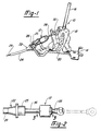
- Figure 1 is a pictorial view of a shifter assembly of an illustrative motor vehicle showing a transmission shifter lever coupled to a transmission shift cable assembly incorporating the in-line solenoid transmission interlock device according to this invention.
- Figure 2 is a side elevational view of the end of the in-line solenoid transmission interlock device shown in Figure 1.
- Figure 3 is a longitudinal cross-sectional view taken along line 3-3 of Figure 2 particularly showing details of the internal components of the solenoid device.
- Figure 4 is a longitudinal cross-sectional view of an in-line solenoid transmission interlock device according to a second embodiment of this invention incorporating a self-adjusting mechanism and dual position locking capability.
- FIG. 1 illustrates a motor vehicle automatic transmission shifter assembly 10 with an in-line solenoid transmission interlock device 12 coupled thereto in accordance with this invention.
- Shifter assembly 10 includes mounting plate 14 for mounting the device to the floor pan of a motor vehicle.
- Shifter lever 16 is pivotable through a limited angular range with various angular positions corresponding to a particular transmission gear selection.
- Shifter lever 16 is mounted to clevis 18 which is pinned for rotation with respect to plate 16 by clevis pin 20.
- Transmission shift cable assembly 22 includes an outer sheath 24 with an end fitting 25 which is supported by plate 14 at restraining notch 26.
- Shift cable rod 28 attached to an end of cable core 29 is affixed to clevis 18 via pin 30 such that arcuate motion of shifter lever 16 causes the rod to be moved into and out of outer sheath 24, as shown by the full and phantom line positions in Figure 2.
- Shifter assembly 10 would further include (not shown) some means for indicating to the operator the transmission selection position which shifter lever 16 is set at. Such indicia can be provided, for example, in the form of a labeled elongated slot through which shifter lever 16 passes, or through a remotely actuated shift indicator device which are well known according to the prior art.
- the opposite end of cable assembly 22 (not shown) is coupled to the vehicle's automatic transmission.
- a bracket is provided which restrains outer sheath 24 whereas cable inner core 29 engages a transmission shift actuating lever.
- cable assembly 22 includes solenoid device 12 which provides the interlock function such that rod 28 is restrained at a particular position with respect to cable outer sheath 24 until the device is released.
- solenoid device 12 which provides the interlock function such that rod 28 is restrained at a particular position with respect to cable outer sheath 24 until the device is released.
- Rod guide 36 defines elongated internal bore 38 through which shifter rod 28 is longitudinally movable.
- Rod guide 36 further forms a radially extending circular flange 40 which forms a point of support for the remainder of solenoid 12.
- Cylindrical housing 42 encloses solenoid 12 and is mounted to flange 40 at rolled over edge 44.
- Pole piece 46 is fixedly mounted within housing 42 and encircles rod guide 36.
- Pole piece 46 further defines a radially extending flange 48 which acts as a flux collector at one of its axial ends, and forms a convex frusto-conical surface 50 at its opposite end.
- Counterbore 52 is formed within pole piece 46 at its end adjacent surface 50.
- Armature 54 is movable in an axial direction through a limited range of motion along rod guide 36 and includes a concave frusto-conical surface 56 which corresponds in shape to that of pole piece surface 50. Armature 54 further defines a pair of annular grooves 58 and 60 with groove 60 being deeper in a radial direction than groove 58 and having a conical ramp surface 62 joining the grooves.
- Coil bobbin 66 encircles pole piece 46 and armature 54, and forms a pair of axially separated flanges 68 and 70 which confine and support coil winding 72.
- Bobbin 66 further forms an end cup 74 which encloses one end of armature 54 but permits a limited range of longitudinal motion of the armature.
- Flux collector ring 76 is positioned adjacent flange 70.
- Return spring 78 is disposed within counterbore 52 and biases armature 54 away from pole piece 46.
- an inwardly formed annular groove 82 is provided at one or more axial positions along shifter rod 28.
- One or more radial holes 84 is provided through rod guide 36 at a position aligned with groove 82 when the transmission is set in the park position. Balls 86 are loaded into holes 84 and provide a locking function as will be described hereinafter.
- Figure 3 illustrates the orientation and cooperation of elements of interlock solenoid 12 when winding 72 is energized which causes the transmission to be locked in the park position.
- armature 54 is drawn toward pole piece 46 caused by the induced magnetic field from winding 72.
- the tapered working air gap provided by the frusto-conical surfaces 50 and 56 provide a desired level of attractive force of armature 54 over a fairly long stroke distance of the armature.
- alternately shaped working air gaps such as planar air gaps could also be used.
- balls 86 are forced in a radially inward direction through engagement with ramp surface 62 and groove 58 such that they interlockingly engage with rod groove 82.
- Figure 4 illustrates a second embodiment of a solenoid interlock device 110 in accordance with this invention. Elements of device 110 which are identical to those previously described in connection with the first embodiment are identified by like reference numbers.
- solenoid interlock device 112 is substantially identical to that shown in Figure 3 except that a modified rod guide 112 is provided which acts as an adjustment link.
- Rod guide 112 forms an enlarged cavity 114 having inwardly directed teeth 116 therein.
- Cable outer sheath 24 includes a ribbed or toothed plunger 118 interfitting within cavity 114. The teeth 116 and plunger 118 interact so that the plunger can be inserted at various depths within cavity 114 but is restrained from being withdrawn.
- modified rod guide 112 and plunger 118 The function of modified rod guide 112 and plunger 118 is to provide a means for adjusting the effective length of outer sheath 24 to accommodate tolerance variations in the vehicle and cable assemblies.
- solenoid device 110 is positioned for engagement of locking balls 86 with groove 82.
- the transmission shift lever (not shown) is placed in the park position and the opposite end of the cable is mounted. Due to tension between cable core 29 and outer sheath 24, plunger 118 is forced within cavity 114 to the proper position.
- Modified solenoid device 110 as shown in Figure 4 further incorporates an additional locking groove 120 which enables interlock device 110 to lock at two positions, thus enabling the manufacturer to provide interlock capability operable at either the neutral or park transmission selector positions.
Landscapes
- Engineering & Computer Science (AREA)
- General Engineering & Computer Science (AREA)
- Mechanical Engineering (AREA)
- Health & Medical Sciences (AREA)
- Oral & Maxillofacial Surgery (AREA)
- Gear-Shifting Mechanisms (AREA)
- Arrangement Or Mounting Of Control Devices For Change-Speed Gearing (AREA)
Abstract
Description
- The invention relates to an automatic transmission shifter interlock device for a motor vehicle of the type having a cable assembly with an outer sheath and an axially movable inner core therein, with said inner core coupled at opposite ends to a shifter lever and the transmission of said vehicle, a rod connected to said cable core, a tubular rod guide encircling said rod and guiding said rod for axial movement, and releasable rod locking means for inhibiting axial movement of said rod.
- An interlock device is known from document GB-A-2019963. A gear selector mechanism for a gearbox described within this document comprises a shaft or a rod axially slidable in a tubular housing. The shaft being movable axially by means of an actuator member which moves in the direction of movement of the shaft. The actuator member is actuated by a shifter lever via a cable. Locking means are provided to lock the shaft against movement relative to the housing. However, an initial movement of the actuator member away from an end position unlocks the locking means and on further movement, when the motion has been taken up, it moves the shaft.
- It is the object of the present invention to provide an interlock device making it unable to move the shifter lever in a locked position.
- This object is achieved by a pole piece encircling said rod guide, an armature encircling said rod guide and axially movable between a first position displaced from said pole piece and a second position attracted toward said pole piece, a solenoid winding encircling said pole piece and said armature and urging said armature toward said second position when energized, biasing means for urging said armature toward said first position, and wherein said rod locking means inhibits axial movement of said rod when said armature is in said second position and permitting said axial movement when said armature is in said first position, whereby energization of said winding prevents the motor vehicle operator from changing transmission shifter settings whereas de-energization permits said changing.
- This invention is directed toward a design for a shifter interlock device which is particularly adapted for motor vehicles having automatic transmissions which are shifted through an actuation cable. The invention employs an electrically energized solenoid positioned in-line with the cable which forces locking elements into engagement with a cable shaft until some action is taken such as when the vehicle's brake pedal is depressed, whereupon the locking elements are permitted to disengage the shaft, thus permitting free movement of the shifter cable. Since most modern vehicles with automatic transmissions use shift cables, the device according to this invention is highly adaptable for use with many motor vehicle models produced by various manufacturers. The present device further restrains movement of the transmission shift cable directly at the transmission shift lever and, therefore, attempts to actuate the shifter while the device is locked do not put extreme loads on the cable. The principal components of the device according to this invention are positioned within the vehicle's occupant compartment where they are protected from the severe outside environment. In accordance with a preferred embodiment of the invention, an adjusting mechanism is provided to accommodate tolerance variations which enables the effective length of the shift cable to be adjusted to provide locking engagement of the device at the desired shifter position.
- Additional benefits and advantages of the present invention will become apparent to those skilled in the art to which this invention relates from the subsequent description of the preferred embodiments and the appended claims, taken in conjunction with the accompanying drawings.
- Figure 1 is a pictorial view of a shifter assembly of an illustrative motor vehicle showing a transmission shifter lever coupled to a transmission shift cable assembly incorporating the in-line solenoid transmission interlock device according to this invention.
- Figure 2 is a side elevational view of the end of the in-line solenoid transmission interlock device shown in Figure 1.
- Figure 3 is a longitudinal cross-sectional view taken along line 3-3 of Figure 2 particularly showing details of the internal components of the solenoid device.
- Figure 4 is a longitudinal cross-sectional view of an in-line solenoid transmission interlock device according to a second embodiment of this invention incorporating a self-adjusting mechanism and dual position locking capability.
- Figure 1 illustrates a motor vehicle automatic
transmission shifter assembly 10 with an in-line solenoidtransmission interlock device 12 coupled thereto in accordance with this invention.Shifter assembly 10 includes mounting plate 14 for mounting the device to the floor pan of a motor vehicle. Shifter lever 16 is pivotable through a limited angular range with various angular positions corresponding to a particular transmission gear selection. Shifter lever 16 is mounted toclevis 18 which is pinned for rotation with respect to plate 16 byclevis pin 20. - Transmission
shift cable assembly 22 includes anouter sheath 24 with anend fitting 25 which is supported by plate 14 at restrainingnotch 26.Shift cable rod 28 attached to an end ofcable core 29 is affixed toclevis 18 viapin 30 such that arcuate motion of shifter lever 16 causes the rod to be moved into and out ofouter sheath 24, as shown by the full and phantom line positions in Figure 2.Shifter assembly 10 would further include (not shown) some means for indicating to the operator the transmission selection position which shifter lever 16 is set at. Such indicia can be provided, for example, in the form of a labeled elongated slot through which shifter lever 16 passes, or through a remotely actuated shift indicator device which are well known according to the prior art. The opposite end of cable assembly 22 (not shown) is coupled to the vehicle's automatic transmission. At the transmission, a bracket is provided which restrainsouter sheath 24 whereas cableinner core 29 engages a transmission shift actuating lever. - In accordance with a principal feature of this invention,
cable assembly 22 includessolenoid device 12 which provides the interlock function such thatrod 28 is restrained at a particular position with respect to cableouter sheath 24 until the device is released. With particular reference to Figures 2 and 3, the components making upsolenoid device 12 are shown.Rod guide 36 defines elongatedinternal bore 38 through whichshifter rod 28 is longitudinally movable.Rod guide 36 further forms a radially extendingcircular flange 40 which forms a point of support for the remainder ofsolenoid 12.Cylindrical housing 42 enclosessolenoid 12 and is mounted toflange 40 at rolled overedge 44.Pole piece 46 is fixedly mounted withinhousing 42 andencircles rod guide 36.Pole piece 46 further defines a radially extendingflange 48 which acts as a flux collector at one of its axial ends, and forms a convex frusto-conical surface 50 at its opposite end.Counterbore 52 is formed withinpole piece 46 at its endadjacent surface 50. -
Armature 54 is movable in an axial direction through a limited range of motion alongrod guide 36 and includes a concave frusto-conical surface 56 which corresponds in shape to that ofpole piece surface 50.Armature 54 further defines a pair ofannular grooves groove 60 being deeper in a radial direction thangroove 58 and having aconical ramp surface 62 joining the grooves.Coil bobbin 66encircles pole piece 46 andarmature 54, and forms a pair of axially separatedflanges end cup 74 which encloses one end ofarmature 54 but permits a limited range of longitudinal motion of the armature.Flux collector ring 76 is positionedadjacent flange 70.Return spring 78 is disposed withincounterbore 52 andbiases armature 54 away frompole piece 46. - At one or more axial positions along
shifter rod 28, an inwardly formedannular groove 82 is provided. One or moreradial holes 84 is provided throughrod guide 36 at a position aligned withgroove 82 when the transmission is set in the park position.Balls 86 are loaded intoholes 84 and provide a locking function as will be described hereinafter. - Figure 3 illustrates the orientation and cooperation of elements of
interlock solenoid 12 when winding 72 is energized which causes the transmission to be locked in the park position. As shown,armature 54 is drawn towardpole piece 46 caused by the induced magnetic field from winding 72. The tapered working air gap provided by the frusto-conical surfaces armature 54 over a fairly long stroke distance of the armature. However, alternately shaped working air gaps such as planar air gaps could also be used. In the position shown in Figure 3,balls 86 are forced in a radially inward direction through engagement withramp surface 62 andgroove 58 such that they interlockingly engage withrod groove 82. In this condition, the vehicle operator is prevented from moving shifter lever 16 to causerod 28 to move longitudinally withinguide 36. If, however, electric current is interrupted to winding 72 caused, for example, by the operator depressing the vehicle's brake pedal, the magnetic attraction betweenpole piece 46 andarmature 54 is relieved and the biasing force ofspring 78 moves thearmature 54 away from the pole piece. Oncearmature 54 is fully extended away frompole piece 46,balls 86 are permitted to move radially outward to seat withingroove 60, thus no longer interlockingly engagingrod groove 82. - Figure 4 illustrates a second embodiment of a
solenoid interlock device 110 in accordance with this invention. Elements ofdevice 110 which are identical to those previously described in connection with the first embodiment are identified by like reference numbers. For this embodiment,solenoid interlock device 112 is substantially identical to that shown in Figure 3 except that a modifiedrod guide 112 is provided which acts as an adjustment link.Rod guide 112 forms an enlargedcavity 114 having inwardly directedteeth 116 therein. Cableouter sheath 24 includes a ribbed ortoothed plunger 118 interfitting withincavity 114. Theteeth 116 andplunger 118 interact so that the plunger can be inserted at various depths withincavity 114 but is restrained from being withdrawn. The function of modifiedrod guide 112 andplunger 118 is to provide a means for adjusting the effective length ofouter sheath 24 to accommodate tolerance variations in the vehicle and cable assemblies. In use,solenoid device 110 is positioned for engagement oflocking balls 86 withgroove 82. The transmission shift lever (not shown) is placed in the park position and the opposite end of the cable is mounted. Due to tension betweencable core 29 andouter sheath 24,plunger 118 is forced withincavity 114 to the proper position. -
Modified solenoid device 110 as shown in Figure 4 further incorporates anadditional locking groove 120 which enablesinterlock device 110 to lock at two positions, thus enabling the manufacturer to provide interlock capability operable at either the neutral or park transmission selector positions. - While the above description constitutes the prefered embodiments of the present invention, it will be appreciated that the invention is susceptible to modification, variation and change without departing from the proper scope and fair meaning of the accompanying claims.
Claims (6)
- An automatic transmission shifter interlock device for a motor vehicle of the type having a cable assembly (10) with an outer sheath (24) and an axially movable inner core (29) therein, with said inner core (29) coupled at opposite ends to a shifter lever (16) and the transmission of said vehicle, a rod (28) connected to said cable core (29), a tubular rod guide (36) encircling said rod (28) and guiding said rod (28) for axial movement, and releasable rod locking means comprising a locking element and groove arrangement for inhibiting axial movement of said rod, characterized by:- a pole piece (46) encircling said rod guide (36),- an armature (54) encircling said rod guide (36) and axially movable between a first position displaced from said pole piece (46) and a second position attracted toward said pole piece (46),- a solenoid winding (72) encircling said pole piece (46) and said armature (54) and urging said armature (54) toward said second position when energized,- biasing means (78) for urging said armature (54) toward said first position, and wherein- said rod locking means inhibits axial movement of said rod (28) when said armature (54) is in said second position and permitting said axial movement when said armature (54) is in said first position, whereby energization of said winding (72) prevents the motor vehicle operator from changing transmission shifter settings whereas de-energization permits said changing.
- An interlock device according to claim 1, wherein said rod locking means comprises said armature (54) defining an inside groove (58) which engages at least one ball element (86) when in said one position to urge said ball (86) into engagement with a groove (82) on a movable portion of said rod (28).
- An interlock device according to claim 2, wherein said movable portion of said rod (28) defines at least two of said grooves (82, 120).
- An interlock device according to any one of claims 1 - 3 wherein said rod locking means inhibits axial movement of said cable inner core (29) when said armature (54) is in said second position.
- An interlock device according to claim 4, further comprising spring means (78) urging said armature (54) to said first position.
- An interlock device according to any one of claims 1 - 5, further comprising cable length adjustment means including said outer sheath (24) having an adjustable link with a first set of engagement members affixed to one portion of said cable sheath (24) and a second set of engagement members affixed to another portion of said cable sheath (24), said engagement members enabling the collapsing of said adjustment link but inhibiting expansion of said link.
Applications Claiming Priority (2)
| Application Number | Priority Date | Filing Date | Title |
|---|---|---|---|
| US23407488A | 1988-08-19 | 1988-08-19 | |
| US234074 | 1988-08-19 |
Publications (2)
| Publication Number | Publication Date |
|---|---|
| EP0356769A1 EP0356769A1 (en) | 1990-03-07 |
| EP0356769B1 true EP0356769B1 (en) | 1993-02-17 |
Family
ID=22879789
Family Applications (1)
| Application Number | Title | Priority Date | Filing Date |
|---|---|---|---|
| EP89114622A Expired - Lifetime EP0356769B1 (en) | 1988-08-19 | 1989-08-08 | In-line solenoid transmission interlock device |
Country Status (3)
| Country | Link |
|---|---|
| EP (1) | EP0356769B1 (en) |
| CA (1) | CA1325957C (en) |
| DE (1) | DE68904937T2 (en) |
Cited By (1)
| Publication number | Priority date | Publication date | Assignee | Title |
|---|---|---|---|---|
| US8602194B2 (en) | 2006-10-24 | 2013-12-10 | Steering Solutions Ip Holding Corporation | Brake-transmission shift interlock assembly |
Families Citing this family (7)
| Publication number | Priority date | Publication date | Assignee | Title |
|---|---|---|---|---|
| JPH0719879Y2 (en) * | 1988-12-27 | 1995-05-10 | 富士重工業株式会社 | Shift lock device for AT vehicles |
| GB9013403D0 (en) * | 1990-06-15 | 1990-08-08 | Ibm | Lock mechanism |
| US5522277A (en) * | 1995-06-12 | 1996-06-04 | Carter Automotive Company, Inc. | Electrically-operated latch |
| DE19834156A1 (en) | 1998-07-29 | 2000-02-03 | Zahnradfabrik Friedrichshafen | Parking lock, in particular for automatic transmissions of motor vehicles |
| DE10037565A1 (en) * | 2000-08-02 | 2002-04-04 | Zahnradfabrik Friedrichshafen | Parking lock, in particular for a motor vehicle transmission |
| KR101056959B1 (en) | 2011-01-27 | 2011-08-16 | 주식회사 유니크 | Solenoid valve and parking lock device for automatic transmission including the same |
| DE102016209411A1 (en) * | 2016-05-31 | 2017-11-30 | Volkswagen Aktiengesellschaft | Device for actuating a parking lock of a motor vehicle transmission |
Family Cites Families (4)
| Publication number | Priority date | Publication date | Assignee | Title |
|---|---|---|---|---|
| US4187935A (en) * | 1978-02-28 | 1980-02-12 | Hern Thomas R O | Brake operated shift lock |
| GB2019963B (en) * | 1978-03-03 | 1982-08-18 | Telehoist Ltd | Gear selector |
| CA1203756A (en) * | 1983-08-03 | 1986-04-29 | George B. Murphy | Transmission park lock mechanism |
| FR2572037B1 (en) * | 1984-10-22 | 1991-03-29 | Barbarot Gisele | ANTI-THEFT DEVICE AND METHOD, IN PARTICULAR FOR A MOTOR VEHICLE, ACTING BY BLOCKING THE ACTION OF THE CLUTCH CABLE |
-
1989
- 1989-05-15 CA CA000599646A patent/CA1325957C/en not_active Expired - Fee Related
- 1989-08-08 EP EP89114622A patent/EP0356769B1/en not_active Expired - Lifetime
- 1989-08-08 DE DE8989114622T patent/DE68904937T2/en not_active Expired - Fee Related
Cited By (1)
| Publication number | Priority date | Publication date | Assignee | Title |
|---|---|---|---|---|
| US8602194B2 (en) | 2006-10-24 | 2013-12-10 | Steering Solutions Ip Holding Corporation | Brake-transmission shift interlock assembly |
Also Published As
| Publication number | Publication date |
|---|---|
| DE68904937D1 (en) | 1993-03-25 |
| CA1325957C (en) | 1994-01-11 |
| EP0356769A1 (en) | 1990-03-07 |
| DE68904937T2 (en) | 1993-08-26 |
Similar Documents
| Publication | Publication Date | Title |
|---|---|---|
| US4987968A (en) | In-line solenoid transmission interlock device | |
| CA1297385C (en) | Control device for an automatic transmission in a motor vehicle | |
| US4966262A (en) | Transmission safety locking lever apparatus | |
| US8053691B2 (en) | Park inhibition solenoid assembly | |
| EP0784766B1 (en) | Shift control mechanism to manually shift an automatic transmission | |
| US4947968A (en) | Transmission mounted solenoid interlock device | |
| CA2191840C (en) | Shift control mechanism to manually shift an automatic transmission | |
| USRE35772E (en) | Solenoid system for, for example, a brake/shift interlock for vehicular transmission control | |
| US5176231A (en) | Interlock device having reduced preload binding | |
| WO1996006751A1 (en) | Electronic park lock | |
| EP0356769A1 (en) | In-line solenoid transmission interlock device | |
| US20170133138A1 (en) | Solenoid system with an armature position sensor | |
| EP0030783A2 (en) | Automotive transmission shifter and park lock assembly | |
| US6026702A (en) | Operating device with single-shaft actuation | |
| US6282979B1 (en) | Adjustment assembly for an integral shifter cable interlock | |
| EP0852307B1 (en) | Shift lock units for shift lever devices | |
| US6533705B1 (en) | Shifting device for the gearbox of a motor vehicle | |
| US3361234A (en) | Transmission control mechanism | |
| EP0390590A1 (en) | Shift lever arrangement for operating automatic power transmission | |
| US20020112558A1 (en) | Shift device for a motor vehicle gearbox | |
| US6231476B1 (en) | Park-lock shifter cable | |
| CA2189464C (en) | Transmission control lever with return to neutral function | |
| NZ248734A (en) | Solenoid operated lost motion link for vehicle accelerator linkage | |
| EP0170630A1 (en) | Gearbox control device for motor vehicles | |
| EP1717461A1 (en) | Shifter assembly with cable adjuster |
Legal Events
| Date | Code | Title | Description |
|---|---|---|---|
| PUAI | Public reference made under article 153(3) epc to a published international application that has entered the european phase |
Free format text: ORIGINAL CODE: 0009012 |
|
| AK | Designated contracting states |
Kind code of ref document: A1 Designated state(s): DE FR GB IT |
|
| 17P | Request for examination filed |
Effective date: 19900321 |
|
| 17Q | First examination report despatched |
Effective date: 19910516 |
|
| GRAA | (expected) grant |
Free format text: ORIGINAL CODE: 0009210 |
|
| AK | Designated contracting states |
Kind code of ref document: B1 Designated state(s): DE FR GB IT |
|
| ITF | It: translation for a ep patent filed | ||
| REF | Corresponds to: |
Ref document number: 68904937 Country of ref document: DE Date of ref document: 19930325 |
|
| ET | Fr: translation filed | ||
| PLBE | No opposition filed within time limit |
Free format text: ORIGINAL CODE: 0009261 |
|
| STAA | Information on the status of an ep patent application or granted ep patent |
Free format text: STATUS: NO OPPOSITION FILED WITHIN TIME LIMIT |
|
| 26N | No opposition filed | ||
| REG | Reference to a national code |
Ref country code: GB Ref legal event code: IF02 |
|
| PGFP | Annual fee paid to national office [announced via postgrant information from national office to epo] |
Ref country code: GB Payment date: 20020626 Year of fee payment: 14 |
|
| PGFP | Annual fee paid to national office [announced via postgrant information from national office to epo] |
Ref country code: FR Payment date: 20020805 Year of fee payment: 14 |
|
| PGFP | Annual fee paid to national office [announced via postgrant information from national office to epo] |
Ref country code: DE Payment date: 20020830 Year of fee payment: 14 |
|
| PG25 | Lapsed in a contracting state [announced via postgrant information from national office to epo] |
Ref country code: GB Free format text: LAPSE BECAUSE OF NON-PAYMENT OF DUE FEES Effective date: 20030808 |
|
| PG25 | Lapsed in a contracting state [announced via postgrant information from national office to epo] |
Ref country code: DE Free format text: LAPSE BECAUSE OF NON-PAYMENT OF DUE FEES Effective date: 20040302 |
|
| GBPC | Gb: european patent ceased through non-payment of renewal fee |
Effective date: 20030808 |
|
| PG25 | Lapsed in a contracting state [announced via postgrant information from national office to epo] |
Ref country code: FR Free format text: LAPSE BECAUSE OF NON-PAYMENT OF DUE FEES Effective date: 20040430 |
|
| REG | Reference to a national code |
Ref country code: FR Ref legal event code: ST |
|
| PG25 | Lapsed in a contracting state [announced via postgrant information from national office to epo] |
Ref country code: IT Free format text: LAPSE BECAUSE OF NON-PAYMENT OF DUE FEES Effective date: 20050808 |