EP0356205B1 - A battery and battery receptacle arrangement - Google Patents
A battery and battery receptacle arrangement Download PDFInfo
- Publication number
- EP0356205B1 EP0356205B1 EP89308508A EP89308508A EP0356205B1 EP 0356205 B1 EP0356205 B1 EP 0356205B1 EP 89308508 A EP89308508 A EP 89308508A EP 89308508 A EP89308508 A EP 89308508A EP 0356205 B1 EP0356205 B1 EP 0356205B1
- Authority
- EP
- European Patent Office
- Prior art keywords
- battery
- receptacle
- arrangement
- projection
- arrangement according
- Prior art date
- Legal status (The legal status is an assumption and is not a legal conclusion. Google has not performed a legal analysis and makes no representation as to the accuracy of the status listed.)
- Expired - Lifetime
Links
- 230000015572 biosynthetic process Effects 0.000 claims abstract description 14
- 238000010276 construction Methods 0.000 claims description 5
- 230000006835 compression Effects 0.000 description 3
- 238000007906 compression Methods 0.000 description 3
- 230000004048 modification Effects 0.000 description 2
- 238000012986 modification Methods 0.000 description 2
- 239000002537 cosmetic Substances 0.000 description 1
- 239000000463 material Substances 0.000 description 1
- 239000002184 metal Substances 0.000 description 1
- 238000005192 partition Methods 0.000 description 1
- 229920003023 plastic Polymers 0.000 description 1
- 239000004033 plastic Substances 0.000 description 1
Images


Classifications
-
- A—HUMAN NECESSITIES
- A61—MEDICAL OR VETERINARY SCIENCE; HYGIENE
- A61F—FILTERS IMPLANTABLE INTO BLOOD VESSELS; PROSTHESES; DEVICES PROVIDING PATENCY TO, OR PREVENTING COLLAPSING OF, TUBULAR STRUCTURES OF THE BODY, e.g. STENTS; ORTHOPAEDIC, NURSING OR CONTRACEPTIVE DEVICES; FOMENTATION; TREATMENT OR PROTECTION OF EYES OR EARS; BANDAGES, DRESSINGS OR ABSORBENT PADS; FIRST-AID KITS
- A61F2/00—Filters implantable into blood vessels; Prostheses, i.e. artificial substitutes or replacements for parts of the body; Appliances for connecting them with the body; Devices providing patency to, or preventing collapsing of, tubular structures of the body, e.g. stents
- A61F2/50—Prostheses not implantable in the body
- A61F2/68—Operating or control means
- A61F2/70—Operating or control means electrical
-
- H—ELECTRICITY
- H01—ELECTRIC ELEMENTS
- H01M—PROCESSES OR MEANS, e.g. BATTERIES, FOR THE DIRECT CONVERSION OF CHEMICAL ENERGY INTO ELECTRICAL ENERGY
- H01M50/00—Constructional details or processes of manufacture of the non-active parts of electrochemical cells other than fuel cells, e.g. hybrid cells
- H01M50/20—Mountings; Secondary casings or frames; Racks, modules or packs; Suspension devices; Shock absorbers; Transport or carrying devices; Holders
- H01M50/202—Casings or frames around the primary casing of a single cell or a single battery
-
- A—HUMAN NECESSITIES
- A61—MEDICAL OR VETERINARY SCIENCE; HYGIENE
- A61F—FILTERS IMPLANTABLE INTO BLOOD VESSELS; PROSTHESES; DEVICES PROVIDING PATENCY TO, OR PREVENTING COLLAPSING OF, TUBULAR STRUCTURES OF THE BODY, e.g. STENTS; ORTHOPAEDIC, NURSING OR CONTRACEPTIVE DEVICES; FOMENTATION; TREATMENT OR PROTECTION OF EYES OR EARS; BANDAGES, DRESSINGS OR ABSORBENT PADS; FIRST-AID KITS
- A61F2/00—Filters implantable into blood vessels; Prostheses, i.e. artificial substitutes or replacements for parts of the body; Appliances for connecting them with the body; Devices providing patency to, or preventing collapsing of, tubular structures of the body, e.g. stents
- A61F2/0095—Packages or dispensers for prostheses or other implants
-
- Y—GENERAL TAGGING OF NEW TECHNOLOGICAL DEVELOPMENTS; GENERAL TAGGING OF CROSS-SECTIONAL TECHNOLOGIES SPANNING OVER SEVERAL SECTIONS OF THE IPC; TECHNICAL SUBJECTS COVERED BY FORMER USPC CROSS-REFERENCE ART COLLECTIONS [XRACs] AND DIGESTS
- Y02—TECHNOLOGIES OR APPLICATIONS FOR MITIGATION OR ADAPTATION AGAINST CLIMATE CHANGE
- Y02E—REDUCTION OF GREENHOUSE GAS [GHG] EMISSIONS, RELATED TO ENERGY GENERATION, TRANSMISSION OR DISTRIBUTION
- Y02E60/00—Enabling technologies; Technologies with a potential or indirect contribution to GHG emissions mitigation
- Y02E60/10—Energy storage using batteries
Definitions
- the present invention relates to a battery and battery receptacle arrangement, comprising a battery as a first part of the arrangement, a battery receptacle as a second part of the arrangement, a formation provided on one of the parts, and a corresponding formation provided on the other part, which corresponding formation is engaged by the first-mentioned formation when the battery is inserted in the receptacle and moved transversely therewithin, thereby to retain the battery in the receptacle in a readily releasable manner.
- US-A-3,957,540 discloses such an arrangement which is provided with pivot means at one end by which the battery can be pivoted into the receptacle, and snap-action means at an opposite end by which the battery is releasably held in the receptacle once it is pushed fully home.
- the present invention is directed to a battery and battery receptacle arrangement as set out in the opening paragraph of the present specification, in which a spring member is contained within one of the parts of the arrangement, to urge a slidable member, also accommodated within that part of the arrangement, in a slide direction which is transverse to the said transverse direction of movement of the battery within the receptacle, and a sloping portion of the other part of the arrangement is so positioned that the said slide member engages the sloping portion when the battery is inserted in the receptacle, to resist the otherwise permitted movement of the battery within the receptacle in a transverse direction.
- the or each formation provided on one of the parts may comprise a projection, and the corresponding formation may comprise a hole.
- the or each projection is provided on the battery casing.
- the or each projection has a transverse portion which is spaced from the battery casing or a receptacle wall, as the case may be, and which extends in a transverse direction which is transverse to the outward direction of projection, the receptacle as a whole permitting movement of the battery therewithin in a transverse direction, to enable the projection to be locked onto the receptacle or battery casing as the case may be at the hole, and thereby retain the battery in a readily releasable manner.
- the or each projection preferably has a simple hook construction so that it can be inserted through the hole and hooked onto a portion which defines the hole.
- the projection may be in the form of a stud and the hole may be in the general shape of a keyhole, so that the stud is inserted into the keyhole at the wider portion thereof, and then slid along so that a neck portion of the stud extends through the narrower portion of the keyhole.
- a convenient shape for the battery and the receptacle is a rectangular shape, in which case the transverse direction of permitted movement of the battery within the receptacle is desirably parallel or substantially parallel to the longer sides of the rectangle.
- the or each spring member may be contained within the battery.
- the whole or substantially the whole of the battery fits in the receptacle so that when the battery is inserted in the receptacle an outer surface of the battery casing is flush or substantially flush with a rim of the receptacle.
- the receptacle may then be positioned to define a recess in the outer surface of the prosthesis, and at least the intended outer surface of the battery casing may be skin coloured to improve the cosmetic appearance of the prosthesis. It will be appreciated that the battery can be readily removed for replacement and/or recharging.
- the battery shown in Figures 1 to 4 comprises a casing 10 which, when viewed from above, as shown in Figure 10, is generally rectangular in shape.
- the casing 10 is made of a synthetic plastics material and is made up of a lower section 12 and an upper section 14 sealed to the lower section 12 once the contents of the battery have been inserted.
- Two projections 16 and 18 project downwardly from the bottom of the battery casing 10.
- Two metallic electrical contacts 20 (only one of which is visable in Figure 1) also extend along the underside of the battery casing 10.
- each projection 16 and 18 comprises a portion 22 which extends away from the battery casing, and a portion 24 which is spaced from the battery casing and extends transversly of the direction of outward projection of the portion 22.
- the direction in which the portion 24 extends is along an axis of the battery casing 10, generally parallel to the longer sides of the receptacle, viewing the battery as in Figure 10.
- Each projection 16 and 18 is provided with a slanting surface 25 on a side of the projection opposite to that of the portion 24.
- the projections 16 and 18 are attached to a fuse cover 26 of the battery casing 10, although other positions are possible.
- the receptacle 28 shown in Figures 5 to 8 also has a generally rectangular shape as viewed from above, having substantially the same width as the battery casing 10 as viewed from above, but being slightly longer than the battery casing 10.
- the depth of the receptacle as viewed in Figure 7 or 8 is substantially the same as that of the battery casing as viewed in Figure 1 or 2.
- Two holes 30 and 32 are formed in a bottom wall of the receptacle. The positions of the holes 30 and 32 correspond to the positions of the projections 16 and 18 of the battery casing 10, and have slanting surfaces 34 at respective ends thereof.
- One end of the bottom of the receptacle 28 is provided with a plug 36 from which extend, within the interior of the receptacle in an axial direction along the bottom thereof, two elongate spring metal contacts 38 and 40 which are both curved so that they arch upwardly from the bottom of the receptacle.
- Two wires 42 and 44 extend from the plug 36 from outside of the receptacle, these wires 42 and 44 being respectively electrically connected to the contacts 38 and 40 within the plug 36.
- the end of the receptacle 28 which is further from the plug 36, on the interior thereof, is provided with a spring buffer 46.
- the battery shown in Figures 1 to 4 is inserted in the receptacle shown in Figures 5 to 8 by orienting the battery so that its contacts 20 are in line with the contacts 38 and 40 of the receptacle, lowering the battery downwardly into the receptacle so that the projections 16 and 18 are inserted through the holes 30 and 32 of the receptacle and then moving the battery transversely within the receptacle in an axial direction towards the plug end of the receptacle so that the transverse portions 24 of the projections 16 and 18 engage the outer underside of the receptacle, and the contacts 20 on the battery wipe the contacts 38 and 40 during the transverse movement and are left in firm electrical contact therewith.
- the frictional force exerted between the contacts of the battery and the receptacle by virtue of the normally curved shape of the receptacle spring contacts may be sufficient to hold the battery in position as shown in Figure 9.
- the spring buffer 46 is not essential, it provides a further resistive force by urging the battery in a direction within the receptacle towards the plug end thereof.
- An additional resistance may be achieved by providing the battery casing with a recess on its underside, in the position corresponding to the box 50 shown in broken lines in Figure 5, into which the spring contacts 38 and 40 project when the battery is inserted into the receptacle.
- the resisting forces are readily overcome manually so that the battery can be readily released from the receptacle.
- the movement of the battery away from the plug end of the receptacle causes the slanting surfaces 25 on the projections 16 and 18 to ride up the slanting surface 34 of the holes 30 and 32 to urge the battery upwardly in an outward direction from the receptacle 28.
- Each spring 50 therefore urges its slidable member 52 in a downward direction, movement of the slidable member 52 in that direction being limited by a front edge 58 of the bottom wall of the battery casing 10.
- the two slidable members 52 are positioned at that end of the battery casing 10 which is the one on the other side of the projection 16 from that of the transversely extending portion 24.
- the receptacle 28 is provided with two sloping elements 60 spaced apart at one end thereof.
- the spacing between the sloping elements is the same as that between the slidable members 52 in the battery casing 10.
- Each sloping member 60 has a sloping face 62 which slopes downwardly from an upper surface of the member 60 and towards the hole 30.
- projections may be provided on the receptacle and holes in the battery casing.
Landscapes
- Health & Medical Sciences (AREA)
- Engineering & Computer Science (AREA)
- Vascular Medicine (AREA)
- General Chemical & Material Sciences (AREA)
- Chemical Kinetics & Catalysis (AREA)
- Cardiology (AREA)
- Oral & Maxillofacial Surgery (AREA)
- Transplantation (AREA)
- Chemical & Material Sciences (AREA)
- Electrochemistry (AREA)
- Biomedical Technology (AREA)
- Heart & Thoracic Surgery (AREA)
- Life Sciences & Earth Sciences (AREA)
- Animal Behavior & Ethology (AREA)
- General Health & Medical Sciences (AREA)
- Public Health (AREA)
- Veterinary Medicine (AREA)
- Battery Mounting, Suspending (AREA)
- Electromechanical Clocks (AREA)
Abstract
Description
- The present invention relates to a battery and battery receptacle arrangement, comprising a battery as a first part of the arrangement, a battery receptacle as a second part of the arrangement, a formation provided on one of the parts, and a corresponding formation provided on the other part, which corresponding formation is engaged by the first-mentioned formation when the battery is inserted in the receptacle and moved transversely therewithin, thereby to retain the battery in the receptacle in a readily releasable manner.
- US-A-3,957,540 discloses such an arrangement which is provided with pivot means at one end by which the battery can be pivoted into the receptacle, and snap-action means at an opposite end by which the battery is releasably held in the receptacle once it is pushed fully home.
- Accordingly, the present invention is directed to a battery and battery receptacle arrangement as set out in the opening paragraph of the present specification, in which a spring member is contained within one of the parts of the arrangement, to urge a slidable member, also accommodated within that part of the arrangement, in a slide direction which is transverse to the said transverse direction of movement of the battery within the receptacle, and a sloping portion of the other part of the arrangement is so positioned that the said slide member engages the sloping portion when the battery is inserted in the receptacle, to resist the otherwise permitted movement of the battery within the receptacle in a transverse direction.
- The or each formation provided on one of the parts may comprise a projection, and the corresponding formation may comprise a hole.
- In one convenient construction, the or each projection is provided on the battery casing.
- Preferably, the or each projection has a transverse portion which is spaced from the battery casing or a receptacle wall, as the case may be, and which extends in a transverse direction which is transverse to the outward direction of projection, the receptacle as a whole permitting movement of the battery therewithin in a transverse direction, to enable the projection to be locked onto the receptacle or battery casing as the case may be at the hole, and thereby retain the battery in a readily releasable manner.
- The or each projection preferably has a simple hook construction so that it can be inserted through the hole and hooked onto a portion which defines the hole. Alternatively, the projection may be in the form of a stud and the hole may be in the general shape of a keyhole, so that the stud is inserted into the keyhole at the wider portion thereof, and then slid along so that a neck portion of the stud extends through the narrower portion of the keyhole.
- A convenient shape for the battery and the receptacle is a rectangular shape, in which case the transverse direction of permitted movement of the battery within the receptacle is desirably parallel or substantially parallel to the longer sides of the rectangle.
- The or each spring member may be contained within the battery.
- Advantageously, the whole or substantially the whole of the battery fits in the receptacle so that when the battery is inserted in the receptacle an outer surface of the battery casing is flush or substantially flush with a rim of the receptacle. Such an arrangement is particularly suitable for use in an electrically driven prosthesis. The receptacle may then be positioned to define a recess in the outer surface of the prosthesis, and at least the intended outer surface of the battery casing may be skin coloured to improve the cosmetic appearance of the prosthesis. It will be appreciated that the battery can be readily removed for replacement and/or recharging.
- Examples of battery and battery receptacle arrangements embodying the present invention are illustrated in the accompanying drawings in which:-
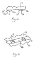
- Figure 1 is a side view of a battery of a first arrangement;
- Figure 2 is an end view of the battery shown in Figure 1, viewing it in the direction of the arrow II in Figure 1;
- Figure 3 is a more detailed representation of parts of the battery shown in Figure 1, viewing it from the other side;
- Figure 4 is a perspective underneath view of the parts shown in Figure 3;
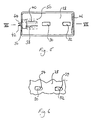
- Figure 5 is a plan view of a receptacle of the arrangement;
- Figure 6 is a more detailed representation of parts of the receptacle shown in Figure 5;
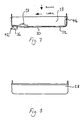
- Figure 7 shows an axial sectional view of the receptacle shown in Figure 5 taken along the line VII-VII shown in that Figure;
- Figure 8 is a side view of the receptacle shown in Figure 7;
- Figure 9 is a partly axial sectional view of the arrangement with the battery releasably inserted in the receptacle;
- Figure 10 shows a plan view of the arrangement shown in Figure 9;
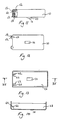
- Figure 11 is a side, partly cut-away view of a battery of a second arrangement;
- Figure 12 is an underneath view of the battery shown in Figure 11;
- Figure 13 is a plan view of a receptacle of the arrangement;
- Figure 14 shows an axial sectional view of the receptacle shown in Figure 13 taken along the line XIV-XIV; and
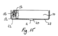
- Figure 15 shows a partly axial sectional view of the second arrangement with the battery releasably inserted in the receptacle.
- The battery shown in Figures 1 to 4 comprises a
casing 10 which, when viewed from above, as shown in Figure 10, is generally rectangular in shape. Thecasing 10 is made of a synthetic plastics material and is made up of alower section 12 and anupper section 14 sealed to thelower section 12 once the contents of the battery have been inserted. Twoprojections battery casing 10. Two metallic electrical contacts 20 (only one of which is visable in Figure 1) also extend along the underside of thebattery casing 10. - As is more evident from Figures 3 and 4, each
projection portion 24 which is spaced from the battery casing and extends transversly of the direction of outward projection of the portion 22. The direction in which theportion 24 extends is along an axis of thebattery casing 10, generally parallel to the longer sides of the receptacle, viewing the battery as in Figure 10. Eachprojection slanting surface 25 on a side of the projection opposite to that of theportion 24. - The
projections fuse cover 26 of thebattery casing 10, although other positions are possible. - The
receptacle 28 shown in Figures 5 to 8 also has a generally rectangular shape as viewed from above, having substantially the same width as thebattery casing 10 as viewed from above, but being slightly longer than thebattery casing 10. The depth of the receptacle as viewed in Figure 7 or 8 is substantially the same as that of the battery casing as viewed in Figure 1 or 2. Twoholes holes projections battery casing 10, and haveslanting surfaces 34 at respective ends thereof. - One end of the bottom of the
receptacle 28 is provided with aplug 36 from which extend, within the interior of the receptacle in an axial direction along the bottom thereof, two elongatespring metal contacts wires plug 36 from outside of the receptacle, thesewires contacts plug 36. - The end of the
receptacle 28 which is further from theplug 36, on the interior thereof, is provided with aspring buffer 46. - The battery shown in Figures 1 to 4 is inserted in the receptacle shown in Figures 5 to 8 by orienting the battery so that its
contacts 20 are in line with thecontacts projections holes transverse portions 24 of theprojections contacts 20 on the battery wipe thecontacts spring buffer 46 is not essential, it provides a further resistive force by urging the battery in a direction within the receptacle towards the plug end thereof. Thus axial movement of the battery in the receptacle in a direction that would release it is resisted. An additional resistance may be achieved by providing the battery casing with a recess on its underside, in the position corresponding to thebox 50 shown in broken lines in Figure 5, into which the spring contacts 38 and 40 project when the battery is inserted into the receptacle. Nonetheless, it will be appreciated that the resisting forces are readily overcome manually so that the battery can be readily released from the receptacle. In this respect, the movement of the battery away from the plug end of the receptacle causes theslanting surfaces 25 on theprojections slanting surface 34 of theholes receptacle 28. - In the modified arrangement shown in Figures 11 to 15, there is only one
projection 16 on the underside of thebattery casing 10, and onecorresponding hole 30 in the bottom wall of thereceptacle 28. Instead of thespring buffer 46, two helical compression springs 50 (only one of which is shown in Figures 11 to 15) are positioned within thebattery casing 10 at one end thereof. Eachspring 50 extends between a top wall of thereceptacle 10 and a slidable member 52, which is free to slide up and down between anend wall 54 of thecasing 10 and apartition wall 56 thereof. Eachspring 50 therefore urges its slidable member 52 in a downward direction, movement of the slidable member 52 in that direction being limited by afront edge 58 of the bottom wall of thebattery casing 10. The two slidable members 52 are positioned at that end of thebattery casing 10 which is the one on the other side of theprojection 16 from that of the transversely extendingportion 24. - The
receptacle 28 is provided with two slopingelements 60 spaced apart at one end thereof. The spacing between the sloping elements is the same as that between the slidable members 52 in thebattery casing 10. Each slopingmember 60 has a slopingface 62 which slopes downwardly from an upper surface of themember 60 and towards thehole 30. - It will be appreciated that the plug and contact construction of the first arrangement illustrated in Figures 1 to 10 is present in the arrangement shown in Figures 11 to 15, although that construction has not been shown in the latter Figures for the sake of clarity.
- When the battery casing shown in Figures 11 and 12 is inserted into the receptacle shown in Figures 13 and 14 it is dropped vertically downwardly therein so that the
projection 16 passes through thehole 30 and the slidable members 52 engage thesloping elements 60. The downward force of the compression springs 50 on the slidable elements 52 urges the latter against thesloping surface 62 of theelement 60, so as to urge the battery casing in a transverse direction, so that theportion 24 extends underneath the bottom wall of thereceptacle 28. This inhibits movement of thebattery casing 10 in an unpward direction away from thereceptacle 28. - To disengage the
battery casing 10 from the receptacle 29, it must first be urged in a transverse direction to disengage theportion 24 from the bottom wall of thereceptacle 28, against the force of thecompression springs 50, until theprojection 16 can once again pass through thehole 30. It is to be noted, that once thebattery casing 10 has been slid transversely in relation to thereceptacle 28 in this way, the force of thesprings 50 will assist in lifting theprojection 16 out of thehole 30. - Numerous variations and modifications may be made to the illustrated arrangements without taking them outside the scope of the present invention. To give one example only of such a modification, projections may be provided on the receptacle and holes in the battery casing.
Claims (9)
- A battery and battery receptacle arrangement (10 and 28), comprising a battery (10) as a first part of the arrangement, a battery receptacle (28) as a second part of the arrangement, a formation (16) provided on one of the parts, and a corresponding formation (30) provided on the other part, which corresponding formation (30) is engaged by the first-mentioned formation (16) when the battery (10) is inserted in the receptacle (28) and moved transversely therewithin, thereby to retain the battery (10) in the receptacle (28) in a readily releasable manner, characterised in that a spring member (50) is contained within one of the parts (10) of the arrangement, to urge a slidable member (52), also accommodated within that part (10) of the arrangement, in a slide direction which is transverse to the said transverse direction of movement of the battery (10) within the receptacle (28), and a sloping portion (60) of the other part (28) of the arrangement is so positioned that the said slide member engages the sloping portion (60) when the battery (10) is inserted in the receptacle (28), to resist the otherwise permitted movement of the battery (10) within the receptacle (28) in a transverse direction.
- An arrangement according to claim 1, characterised in that the formation (16) provided on one of the parts comprises a projection (16), and the corresponding formation (30) comprises a hole (30).
- An arrangement according to claim 2, characterised in that the projection (16) is provided on the battery casing (10).
- An arrangement according to claim 2 or claim 3, characterised in that the projection (16) has a transverse portion (24) which is spaced from the said one of the parts (10), and which extends in a transverse direction which is transverse to the outward direction of projection, the receptacle (28) as a whole permitting movement of the battery (10) therewithin in a transverse direction, to enable the projection (16) to be locked onto the other part (28) at the hole (30) thereof and thereby retain the battery (10) in a readily releasable manner.
- An arrangement according to any one of claims 2 to 4, characterised in that the projection (16) has a simple hook construction (16) so that it can be inserted through the hole (30) and hooked onto a portion which defines the hole (30).
- An arrangement according to any preceding claim, characterised in that both the battery (10) and the receptacle (28) have a rectangular shape, and in which the transverse direction of permitted movement of the battery (10) within the receptacle (28) is parallel or substantially parallel to the longer sides of the rectangle.
- An arrangement according to any preceding claim, characterised in that the part which contains the spring is the battery.
- An arrangement according to any preceding claim, characterised in that substantially the whole of the battery (10) fits in the receptacle (28) so that when the battery (10) is inserted in the receptacle (28) an outer surface of the battery casing (10) is substantially flush with a rim of the receptacle (28).
- A prosthesis having an arrangement according to any preceding claim and positioned in such a manner that the receptacle (28) defines a recess in the outer surface of the prosthesis.
Applications Claiming Priority (2)
| Application Number | Priority Date | Filing Date | Title |
|---|---|---|---|
| GB8820230 | 1988-08-25 | ||
| GB888820230A GB8820230D0 (en) | 1988-08-25 | 1988-08-25 | Battery & battery receptacle arrangement |
Publications (2)
| Publication Number | Publication Date |
|---|---|
| EP0356205A1 EP0356205A1 (en) | 1990-02-28 |
| EP0356205B1 true EP0356205B1 (en) | 1994-05-25 |
Family
ID=10642720
Family Applications (1)
| Application Number | Title | Priority Date | Filing Date |
|---|---|---|---|
| EP89308508A Expired - Lifetime EP0356205B1 (en) | 1988-08-25 | 1989-08-22 | A battery and battery receptacle arrangement |
Country Status (6)
| Country | Link |
|---|---|
| US (1) | US4943498A (en) |
| EP (1) | EP0356205B1 (en) |
| AT (1) | ATE106163T1 (en) |
| CA (1) | CA1319950C (en) |
| DE (1) | DE68915489T2 (en) |
| GB (1) | GB8820230D0 (en) |
Families Citing this family (49)
| Publication number | Priority date | Publication date | Assignee | Title |
|---|---|---|---|---|
| US5251105A (en) * | 1990-06-25 | 1993-10-05 | Kabushiki Kaisha Toshiba | Portable electronic apparatus having a battery pack with a mechanism for latching and an independent mechanism for temporarily preventing detachment |
| DE9015923U1 (en) * | 1990-11-22 | 1992-03-19 | Otto Bock Orthopädische Industrie Besitz- und Verwaltungs-Kommanditgesellschaft, 3408 Duderstadt | accumulator |
| US5217824A (en) * | 1991-10-21 | 1993-06-08 | Womack Robert C | Battery holder |
| JP3263855B2 (en) * | 1992-03-06 | 2002-03-11 | ソニー株式会社 | battery pack |
| CA2408978C (en) * | 1992-05-29 | 2004-12-28 | Sony Corporation | Battery cartridge having hollow electrodes and a recess for detecting misuse and/or recessed terminals |
| JP3289320B2 (en) * | 1992-06-30 | 2002-06-04 | ソニー株式会社 | battery pack |
| AU116519S (en) | 1992-08-07 | 1993-03-16 | Sony Corp | A rechargeable battery |
| USD355637S (en) | 1992-08-31 | 1995-02-21 | Motorola | Battery pack for a portable two-way radio communications device |
| USD356776S (en) | 1992-09-02 | 1995-03-28 | Sony Corporation | Rechargeable battery |
| JP3387124B2 (en) * | 1992-09-02 | 2003-03-17 | ソニー株式会社 | Camera-integrated VTR connection device |
| JP3416962B2 (en) * | 1992-09-18 | 2003-06-16 | ソニー株式会社 | battery pack |
| US5293109A (en) * | 1992-09-28 | 1994-03-08 | Motorola, Inc. | Early recognition battery disconnect |
| US5592069A (en) * | 1992-10-07 | 1997-01-07 | Dallas Semiconductor Corporation | Battery charger |
| KR0110012Y1 (en) * | 1993-07-27 | 1997-12-13 | Samsung Electronics Co Ltd | Battery connector for a camcorder |
| JP2912137B2 (en) * | 1993-09-24 | 1999-06-28 | 日本電気株式会社 | Battery pack holding structure for electronic equipment |
| USD360185S (en) | 1994-03-22 | 1995-07-11 | Sony Corporation | Battery pack |
| USD368067S (en) | 1994-03-23 | 1996-03-19 | Makita Corporation | Battery pack |
| JP3627260B2 (en) * | 1994-09-02 | 2005-03-09 | ソニー株式会社 | Battery device and apparatus for mounting the battery device |
| US5552240A (en) * | 1994-10-25 | 1996-09-03 | The Whitaker Corporation | Battery operated component with removable battery holder |
| USD383433S (en) * | 1995-08-21 | 1997-09-09 | Motorola, Inc. | Battery eliminator housing for a portable radio |
| USD379345S (en) * | 1995-12-08 | 1997-05-20 | Motorola, Inc. | Battery for a portable communication device |
| USD387727S (en) * | 1996-06-28 | 1997-12-16 | Matsushita Electric Industrial Co., Ltd. | Battery |
| USD400494S (en) | 1996-09-13 | 1998-11-03 | Intermec Corporation | Rechargeable battery |
| US5783327A (en) * | 1996-11-26 | 1998-07-21 | Ericsson Inc. | Modular stackable batteries for cellular phones |
| USD401550S (en) | 1996-12-03 | 1998-11-24 | Motorola, Inc. | Battery housing for a portable radio telephone |
| USD397085S (en) | 1997-04-28 | 1998-08-18 | Intermec Technologies Corporation | Battery charger pocket |
| US5909102A (en) * | 1998-01-21 | 1999-06-01 | Motorola, Inc. | Battery connection apparatus employing fixed latching members |
| US6157545A (en) * | 1998-05-14 | 2000-12-05 | Motorola, Inc. | Battery connection apparatus with end projections |
| US6382294B1 (en) | 1999-01-11 | 2002-05-07 | Hunter Douglas Inc. | System for holding batteries in a headrail for powered coverings for architectural openings |
| US6075341A (en) * | 1999-02-17 | 2000-06-13 | Black & Decker Inc. | Power pack charging system for a power tool |
| USD426513S (en) * | 1999-03-12 | 2000-06-13 | Eveready Battery Company, Inc. | Battery pack casing |
| USD437579S1 (en) | 1999-03-12 | 2001-02-13 | Eveready Battery Company, Inc. | Battery pack casing |
| US6326767B1 (en) | 1999-03-30 | 2001-12-04 | Shoot The Moon Products Ii, Llc | Rechargeable battery pack charging system with redundant safety systems |
| US6326766B1 (en) * | 2000-06-09 | 2001-12-04 | Shoot The Moon Products Ii, Llc | Rechargable battery pack and battery pack charger with safety mechanisms |
| USD516502S1 (en) | 2000-06-09 | 2006-03-07 | Shoot The Moon Products Ii, Llc | Rechargeable battery pack |
| US7183745B2 (en) * | 2000-08-11 | 2007-02-27 | Milwaukee Electric Tool Corporation | Adapter for a power tool battery |
| US6525511B2 (en) | 2000-08-11 | 2003-02-25 | Milwaukee Electric Tool Corporation | Adapter for a power tool battery |
| US7443137B2 (en) * | 2000-08-11 | 2008-10-28 | Milwaukee Electric Tool Corporation | Adapter for a power tool battery |
| USD486789S1 (en) | 2003-03-25 | 2004-02-17 | Bissell Homecare, Inc. | Battery pack lower portion |
| JP4123517B2 (en) | 2003-12-26 | 2008-07-23 | ソニー株式会社 | Battery device |
| CN2842523Y (en) * | 2005-09-23 | 2006-11-29 | 鸿富锦精密工业(深圳)有限公司 | Cell module-locking device of electronic apparatus |
| CN2850211Y (en) * | 2005-10-07 | 2006-12-20 | 鸿富锦精密工业(深圳)有限公司 | Cell module locking device for electronic apparatus |
| KR100933424B1 (en) * | 2005-11-23 | 2009-12-23 | 주식회사 엘지화학 | Battery Pack Locker Structure in Notebook Computers |
| JP2008053154A (en) * | 2006-08-28 | 2008-03-06 | Sony Corp | Battery device, electronic device and battery system |
| JP4245017B2 (en) | 2006-08-28 | 2009-03-25 | ソニー株式会社 | Battery device, electronic device and battery system |
| US11196121B2 (en) | 2006-08-28 | 2021-12-07 | Sony Corporation | Battery device, electronic apparatus, and battery system |
| US7820318B2 (en) * | 2007-03-06 | 2010-10-26 | Estop Robotics Llc | Universal battery mount |
| MX2015013588A (en) | 2013-03-26 | 2016-02-05 | Gillette Co | Retarding mechanism. |
| US10033022B2 (en) | 2014-09-30 | 2018-07-24 | Johnson Controls Technology Company | Battery module retention structure |
Family Cites Families (10)
| Publication number | Priority date | Publication date | Assignee | Title |
|---|---|---|---|---|
| US3062911A (en) * | 1960-05-23 | 1962-11-06 | Audivox Inc | Temple piece for spectacles hearing aid |
| US3537909A (en) * | 1968-01-11 | 1970-11-03 | Eastman Kodak Co | Battery holder |
| JPS4916839Y1 (en) * | 1970-12-08 | 1974-04-30 | ||
| US3864172A (en) * | 1973-05-17 | 1975-02-04 | Rca Corp | Battery connecting assembly |
| US3956019A (en) * | 1973-10-29 | 1976-05-11 | Mabuchi Motor Co. Ltd. | Battery cassette power source device |
| US3999110A (en) * | 1975-02-06 | 1976-12-21 | The Black And Decker Manufacturing Company | Battery pack and latch |
| US4041514A (en) * | 1975-05-27 | 1977-08-09 | Polaroid Corporation | Photographic camera having external power supply |
| DE2542933C3 (en) * | 1975-09-26 | 1979-05-03 | Otto Bock Orthopaedische Industrie Kg, 3428 Duderstadt | Accumulator and adapted holder for installation in an electrical external force prosthesis |
| US4237202A (en) * | 1978-11-13 | 1980-12-02 | Teledyne Industries, Inc. | Aircraft battery |
| DE3242320A1 (en) * | 1982-02-12 | 1983-11-24 | General Electric Co., Schenectady, N.Y. | IMPROVED BATTERY COMPARTMENT AND IMPROVED BATTERY BOX |
-
1988
- 1988-08-25 GB GB888820230A patent/GB8820230D0/en active Pending
-
1989
- 1989-08-22 EP EP89308508A patent/EP0356205B1/en not_active Expired - Lifetime
- 1989-08-22 DE DE68915489T patent/DE68915489T2/en not_active Expired - Fee Related
- 1989-08-22 AT AT89308508T patent/ATE106163T1/en not_active IP Right Cessation
- 1989-08-23 CA CA000609205A patent/CA1319950C/en not_active Expired - Fee Related
- 1989-08-23 US US07/397,735 patent/US4943498A/en not_active Expired - Fee Related
Also Published As
| Publication number | Publication date |
|---|---|
| GB8820230D0 (en) | 1988-09-28 |
| EP0356205A1 (en) | 1990-02-28 |
| DE68915489D1 (en) | 1994-06-30 |
| DE68915489T2 (en) | 1994-10-13 |
| CA1319950C (en) | 1993-07-06 |
| ATE106163T1 (en) | 1994-06-15 |
| US4943498A (en) | 1990-07-24 |
Similar Documents
| Publication | Publication Date | Title |
|---|---|---|
| EP0356205B1 (en) | A battery and battery receptacle arrangement | |
| US4952756A (en) | Cover plate for indoor receptacles | |
| US4660912A (en) | Protective cover for electrical outlet | |
| US4857004A (en) | Safety guard for electrical wall outlet | |
| US4915638A (en) | Protective enclosure for electrical outlets | |
| US2932811A (en) | Safety cover for electrical outlets | |
| USD331220S (en) | Battery charger | |
| US5362924A (en) | Protective cover for electrical wall sockets | |
| NL8200362A (en) | BATTERY HOLDER. | |
| WO1992022918A1 (en) | A protection case for remote controls | |
| JPS62500819A (en) | Sheet bundle container | |
| US6056564A (en) | Safety receptacle structure | |
| GB2112751A (en) | Tape cassette container | |
| USD325374S (en) | Electric cord lockbox | |
| US4886465A (en) | Electrical outlet protective cover | |
| US5252083A (en) | Electrical outlet safety cover | |
| US4489836A (en) | Suspension filing means | |
| CA1259241A (en) | Container for a pile of pictures | |
| US4643502A (en) | Duplex outlet protection device | |
| US2744243A (en) | Safety device for electrical receptacles | |
| EP0208680B1 (en) | Single-handledly flippable bag holder | |
| CA1152176A (en) | Shock stop | |
| KR200324750Y1 (en) | Electric outlet safety device | |
| WO2001003248A1 (en) | Electrical outlet safety cover and cord connector | |
| JPH0647366Y2 (en) | Makeup compact container |
Legal Events
| Date | Code | Title | Description |
|---|---|---|---|
| PUAI | Public reference made under article 153(3) epc to a published international application that has entered the european phase |
Free format text: ORIGINAL CODE: 0009012 |
|
| AK | Designated contracting states |
Kind code of ref document: A1 Designated state(s): AT DE FR GB NL SE |
|
| 17P | Request for examination filed |
Effective date: 19900828 |
|
| 17Q | First examination report despatched |
Effective date: 19920323 |
|
| GRAA | (expected) grant |
Free format text: ORIGINAL CODE: 0009210 |
|
| AK | Designated contracting states |
Kind code of ref document: B1 Designated state(s): AT DE FR GB NL SE |
|
| PG25 | Lapsed in a contracting state [announced via postgrant information from national office to epo] |
Ref country code: SE Free format text: THE PATENT HAS BEEN ANNULLED BY A DECISION OF A NATIONAL AUTHORITY Effective date: 19940525 Ref country code: NL Effective date: 19940525 Ref country code: AT Effective date: 19940525 |
|
| REF | Corresponds to: |
Ref document number: 106163 Country of ref document: AT Date of ref document: 19940615 Kind code of ref document: T |
|
| REF | Corresponds to: |
Ref document number: 68915489 Country of ref document: DE Date of ref document: 19940630 |
|
| ET | Fr: translation filed | ||
| PGFP | Annual fee paid to national office [announced via postgrant information from national office to epo] |
Ref country code: FR Payment date: 19940826 Year of fee payment: 6 |
|
| NLV1 | Nl: lapsed or annulled due to failure to fulfill the requirements of art. 29p and 29m of the patents act | ||
| PLBE | No opposition filed within time limit |
Free format text: ORIGINAL CODE: 0009261 |
|
| STAA | Information on the status of an ep patent application or granted ep patent |
Free format text: STATUS: NO OPPOSITION FILED WITHIN TIME LIMIT |
|
| 26N | No opposition filed | ||
| PGFP | Annual fee paid to national office [announced via postgrant information from national office to epo] |
Ref country code: GB Payment date: 19950815 Year of fee payment: 7 |
|
| PGFP | Annual fee paid to national office [announced via postgrant information from national office to epo] |
Ref country code: DE Payment date: 19951030 Year of fee payment: 7 |
|
| PG25 | Lapsed in a contracting state [announced via postgrant information from national office to epo] |
Ref country code: FR Effective date: 19960430 |
|
| REG | Reference to a national code |
Ref country code: FR Ref legal event code: ST |
|
| PG25 | Lapsed in a contracting state [announced via postgrant information from national office to epo] |
Ref country code: GB Effective date: 19960822 |
|
| GBPC | Gb: european patent ceased through non-payment of renewal fee |
Effective date: 19960822 |
|
| PG25 | Lapsed in a contracting state [announced via postgrant information from national office to epo] |
Ref country code: DE Effective date: 19970501 |