EP0356187B1 - Electrophoresis using contour-clamped electric fields - Google Patents
Electrophoresis using contour-clamped electric fields Download PDFInfo
- Publication number
- EP0356187B1 EP0356187B1 EP89308464A EP89308464A EP0356187B1 EP 0356187 B1 EP0356187 B1 EP 0356187B1 EP 89308464 A EP89308464 A EP 89308464A EP 89308464 A EP89308464 A EP 89308464A EP 0356187 B1 EP0356187 B1 EP 0356187B1
- Authority
- EP
- European Patent Office
- Prior art keywords
- electrodes
- resistors
- electric field
- potentials
- gel medium
- Prior art date
- Legal status (The legal status is an assumption and is not a legal conclusion. Google has not performed a legal analysis and makes no representation as to the accuracy of the status listed.)
- Expired - Lifetime
Links
- 230000005684 electric field Effects 0.000 title claims abstract description 25
- 238000001962 electrophoresis Methods 0.000 title abstract description 9
- 238000000034 method Methods 0.000 claims abstract description 10
- 239000002245 particle Substances 0.000 claims abstract description 10
- 239000000872 buffer Substances 0.000 claims description 13
- 238000000926 separation method Methods 0.000 claims description 9
- 238000001514 detection method Methods 0.000 claims 4
- 238000001502 gel electrophoresis Methods 0.000 abstract description 4
- 238000010586 diagram Methods 0.000 description 8
- 229920002521 macromolecule Polymers 0.000 description 6
- 230000008901 benefit Effects 0.000 description 4
- 239000007787 solid Substances 0.000 description 3
- 230000005012 migration Effects 0.000 description 2
- 238000013508 migration Methods 0.000 description 2
- 230000009471 action Effects 0.000 description 1
- 238000007796 conventional method Methods 0.000 description 1
- 239000012634 fragment Substances 0.000 description 1
- 230000014509 gene expression Effects 0.000 description 1
- 230000007246 mechanism Effects 0.000 description 1
- 238000012986 modification Methods 0.000 description 1
- 230000004048 modification Effects 0.000 description 1
- 102000039446 nucleic acids Human genes 0.000 description 1
- 108020004707 nucleic acids Proteins 0.000 description 1
- 150000007523 nucleic acids Chemical class 0.000 description 1
- 102000004169 proteins and genes Human genes 0.000 description 1
- 108090000623 proteins and genes Proteins 0.000 description 1
- 239000000126 substance Substances 0.000 description 1
- 238000006467 substitution reaction Methods 0.000 description 1
- 238000000539 two dimensional gel electrophoresis Methods 0.000 description 1
Images

Classifications
-
- G—PHYSICS
- G01—MEASURING; TESTING
- G01N—INVESTIGATING OR ANALYSING MATERIALS BY DETERMINING THEIR CHEMICAL OR PHYSICAL PROPERTIES
- G01N27/00—Investigating or analysing materials by the use of electric, electrochemical, or magnetic means
- G01N27/26—Investigating or analysing materials by the use of electric, electrochemical, or magnetic means by investigating electrochemical variables; by using electrolysis or electrophoresis
- G01N27/416—Systems
- G01N27/447—Systems using electrophoresis
- G01N27/44704—Details; Accessories
-
- G—PHYSICS
- G01—MEASURING; TESTING
- G01N—INVESTIGATING OR ANALYSING MATERIALS BY DETERMINING THEIR CHEMICAL OR PHYSICAL PROPERTIES
- G01N27/00—Investigating or analysing materials by the use of electric, electrochemical, or magnetic means
- G01N27/26—Investigating or analysing materials by the use of electric, electrochemical, or magnetic means by investigating electrochemical variables; by using electrolysis or electrophoresis
- G01N27/416—Systems
- G01N27/447—Systems using electrophoresis
- G01N27/44704—Details; Accessories
- G01N27/44713—Particularly adapted electric power supply
-
- G—PHYSICS
- G01—MEASURING; TESTING
- G01N—INVESTIGATING OR ANALYSING MATERIALS BY DETERMINING THEIR CHEMICAL OR PHYSICAL PROPERTIES
- G01N27/00—Investigating or analysing materials by the use of electric, electrochemical, or magnetic means
- G01N27/26—Investigating or analysing materials by the use of electric, electrochemical, or magnetic means by investigating electrochemical variables; by using electrolysis or electrophoresis
- G01N27/416—Systems
- G01N27/447—Systems using electrophoresis
- G01N27/44756—Apparatus specially adapted therefor
- G01N27/44773—Multi-stage electrophoresis, e.g. two-dimensional electrophoresis
Definitions
- This invention is in the field of gel electrophoresis and pertains to a method and apparatus for controlling the migration of particles by manipulating the shape and orientation of the electric field in the gel.
- Gel electrophoresis is capable of separating macromolecules such as proteins and nucleic acids on the basis of size, charge, and/or conformation.
- Most applications involve the use of a single pair of electrodes to generate the electric field.
- Such a field is necessarily constrained to be uniform and oriented in a single direction, and as a result conventional techniques are limited in many respects.
- electrophoresis may produce distortion, with molecules at the edge of the gel migrating more slowly than those in the center. Consequently electrophoresis is often done inefficiently at voltages lower than necessary to achieve adequate resolution.
- Yet another object of the present invention is to minimize band broadening in the electrophoretic separation of macromolecules.
- a still further object of this invention is to provide a method for identifying secondary structure in macromolecules.
- the gel was subjected to a uniform or nonuniform field by clamping a plurality of electrodes at predetermined potentials, where at least two electrodes clamped to different potentials serve as the driving electrodes and at least two more electrodes clamped to intermediate potentials serve to further define the nature of the electrical field.
- a uniform or nonuniform field by clamping a plurality of electrodes at predetermined potentials, where at least two electrodes clamped to different potentials serve as the driving electrodes and at least two more electrodes clamped to intermediate potentials serve to further define the nature of the electrical field.
- a structure is provided such that an arbitrary reorientation angle is capable of being provided within a single closed contour.
- a single apparatus defining a single closed contour can be used to provide any desired reorientation angle.
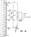
- Figure 1a One embodiment of such a structure is depicted in Figure 1a, in which the reorientation angle is controlled by clamping the corner electrodes to appropriate potentials, for example using the circuit of Fig. 1b.
- resistors R31,R32 with resistance value R i
- R33,R34 with resistance value R j
- Resistors R31 through R34 act as voltage dividers so that the corner electrodes 1, 6, 11, and 16 are clamped to potentials appropriate for a given electric field orientation.
- electrodes 1 and 11 are the driving electrodes (A- and A+)
- electrodes 6 and 16 are clamped to potentials which fix the orientation angle of the electric field, as shown in Figs. 2a and 2b.
- V'' [ 1 1+tan( 1 2 ⁇ ) ] V o
- V' [ R j R i +R j ]
- V o [ 1 1+ R i R j ]
- V o [ 1 1+ R j R i ]
- a variable resistor (typically approximately 20K, 5 watts) is used as resistor R 35 in the B portion of the electrical circuitry in order to cause a lower potential to be used in the B direction than in the A direction, while using a single voltage source V 0 .
- This has the advantage of allowing the structure to be used to, for example, separate DNA on the basis of secondary structure
- solid state relays (such as the Crydon PVR3301) are used as the switching mechanisms, rather than the relay mentioned above. The use of a solid state relay permits more rapid switching, if desired, and provides increased reliability and less audible noise.
- transistor buffer circuits are used between each electrode and the driving circuitry.
- buffer circuits B1 through B24 are used in order to clamp the electrodes to the appropriate potentials more precisely since the resistance paths between electrodes through the chemical buffer are electrically isolated from the resistive voltage divider, thereby allowing the resistive voltage divider to operate more precisely.
- Such buffer circuits have relatively high input impedance, so as not to load down the resistor voltage divider, and a relatively low output impedance, so as to provide adequate clamping of the electrodes. It is to be understood that buffer circuits such as buffer circuits B1 through B20 can be used to advantage in any embodiment of this invention.
- buffer circuits such as buffer circuits B21 through B24 can be used to advantage in any embodiment of this invention.
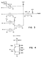
- such buffers are formed as shown in the schematic diagram of Fig. 4 in which emitter follower pull-up and pull-down transistors T98 and T99 are used, respectively.
- the gain provided by the transistors allows the voltage dividers formed by the series of resistors to operate more precisely, without being loaded down by large amounts of current flowing through the resistors.
- the following component values are used:
Landscapes
- Health & Medical Sciences (AREA)
- Life Sciences & Earth Sciences (AREA)
- Molecular Biology (AREA)
- Chemical & Material Sciences (AREA)
- Pathology (AREA)
- Immunology (AREA)
- Physics & Mathematics (AREA)
- Analytical Chemistry (AREA)
- Biochemistry (AREA)
- General Health & Medical Sciences (AREA)
- General Physics & Mathematics (AREA)
- Electrochemistry (AREA)
- Chemical Kinetics & Catalysis (AREA)
- Engineering & Computer Science (AREA)
- Power Engineering (AREA)
- Investigating Or Analysing Biological Materials (AREA)
- Magnetic Resonance Imaging Apparatus (AREA)
- Investigating, Analyzing Materials By Fluorescence Or Luminescence (AREA)
- Peptides Or Proteins (AREA)
- Electrostatic Spraying Apparatus (AREA)
- Apparatus Associated With Microorganisms And Enzymes (AREA)
- Electrostatic Separation (AREA)
- Investigating Or Analyzing Materials By The Use Of Electric Means (AREA)
- Medicines Containing Antibodies Or Antigens For Use As Internal Diagnostic Agents (AREA)
- Measuring Or Testing Involving Enzymes Or Micro-Organisms (AREA)
Abstract
Description
- This invention is in the field of gel electrophoresis and pertains to a method and apparatus for controlling the migration of particles by manipulating the shape and orientation of the electric field in the gel.
- Gel electrophoresis is capable of separating macromolecules such as proteins and nucleic acids on the basis of size, charge, and/or conformation. Most applications involve the use of a single pair of electrodes to generate the electric field. Such a field is necessarily constrained to be uniform and oriented in a single direction, and as a result conventional techniques are limited in many respects.
- For example, conventional electrophoresis is not capable of resolving DNA fragments much larger than 50 kilobases. The recent introduction of new electrode configurations which generate electric fields in alternating orientations has allowed the separation of large DNA molecules up to 2 megabases in size. For example, US-A-4,473,452 describes an electrophoresis method of separating DNA molecules which involves the use of electric fields deliberately chosen to be nonuniform, rather than the uniform fields sought in previously known electrophoresis methods. The nonuniformity of the electric field, however, causes the DNA molecules to migrate with a mobility and a trajectory that depends on where in the gel the sample is loaded. Thus, comparison of multiple samples across the gel is difficult.
- For example, conventional electrophoresis may produce distortion, with molecules at the edge of the gel migrating more slowly than those in the center. Consequently electrophoresis is often done inefficiently at voltages lower than necessary to achieve adequate resolution.
- For example, conventional electrophoresis is limited in resolution by band broadening.
- Also, conventional electrophoresis is not capable of identifying macromolecules with different secondary structure. Two dimensional electrophoresis has been developed for this purpose, but this method is technically difficult because it involves manipulations of the gel.
- It is a principal object of the present invention to provide a method for manipulating the shape and orientation of electric fields for the purpose of controlling the migration of particles in a gel.
- It is another object of the present invention to provide for the high resolution separation of macromolecules, particularly DNA molecules up to or greater than 2 megabases in size, by gel electrophoresis whereby the pattern of separation is independent of position in the gel.
- It is a further object of this invention to provide a means for separating relatively small macromolecules, such as DNA of less than 50 kilobases, without distortion even at high voltage.
- Yet another object of the present invention is to minimize band broadening in the electrophoretic separation of macromolecules.
- A still further object of this invention is to provide a method for identifying secondary structure in macromolecules.
- These and other advantages were disclosed in our earlier EP-A-256737 which was predicated in part on the discovery that the limitations inherent in the existing electrophoretic separation techniques can be overcome by applying contour-clamped uniform or nonuniform electric fields, with the term "contour-clamped electric field" meaning that the electric field is generated by multiple electrodes arranged along a closed contour clamped to predetermined electric potentials, and with the term "uniform electric field" meaning an electric field having a uniform direction and magnitude within a closed contour.
- Depending upon the particular application for the method and apparatus, the gel was subjected to a uniform or nonuniform field by clamping a plurality of electrodes at predetermined potentials, where at least two electrodes clamped to different potentials serve as the driving electrodes and at least two more electrodes clamped to intermediate potentials serve to further define the nature of the electrical field. Thus controlled homogeneity or inhomogeneity could be applied, and the orientation of the field affected.
- In the present invention we go further. We provide for the sequential application of potential to pairs of electrodes at the corners of closed quadrilaterals, with the other electrodes clamped via resistors, with the result that the electric field in the gel can have any desired orientation.
- In the drawings Figure 1a is a schematic vector diagram structure and Figure 1b a schematic diagram of one embodiment of a circuit suitable for driving the electrodes of the structure;
- Figure 2a is a vector diagram and Figure 2b is a circuit model depicting the action at the corners of the contour of the embodiment of Figure 1a;
- Figure 3 is a schematic diagram depicting the use of solid state relays in a switching circuit; and
- Figure 4 is a schematic diagram depicting one embodiment of a circuit suitable for driving an electrode of a structure embodying this invention.
-
- While the invention will be described in connection with certain embodiments, it is not intended to limit the invention to those particular embodiments. On the contrary, it is intended to cover all alternatives, modifications, and equivalent arrangements as may be included within the scope of the invention. For general background, please see EP-A-0256737 and the embodiments described therein.
- While those embodiments allow specific reorientation angles based upon the shape of the closed contour as defined by placement of the electrodes, in an embodiment of the present invention a structure is provided such that an arbitrary reorientation angle is capable of being provided within a single closed contour. Thus, in accordance with this embodiment, a single apparatus defining a single closed contour can be used to provide any desired reorientation angle. One embodiment of such a structure is depicted in Figure 1a, in which the reorientation angle is controlled by clamping the corner electrodes to appropriate potentials, for example using the circuit of Fig. 1b. As shown in Fig. 1b, there are two pairs of resistors R31,R32 (with resistance value Ri) and R33,R34 (with resistance value Rj). In one embodiment of Fig. 1b,
R1 - R20 2K 1 / 2 W R31, R33 10K 2W R32, R34 up to 20K 2W - Resistors R31 through R34 act as voltage dividers so that the
corner electrodes electrodes 1 and 11 are the driving electrodes (A- and A+),electrodes - For a field orientation at an
angle 1 / 2 with respect to the vertical (i.e., a reorientation angle of between alternating fields), V' should reflect the relative perpendicular distances from the driving electrodes. Those distances are x and y in Fig. 2a, - A similar calculation yields
- The resistive voltage bridge in Fig. 2b produces potentials V' and V'' with the correct relationship:
- Thus, if the angle is defined by the relationship,
Equations Equations Equations orientation angle 1 / 2 , proving the validity ofEquation 1. - In another embodiment, as shown in the schematic diagram of Fig. 1b, a variable resistor (typically approximately 20K, 5 watts) is used as resistor R35 in the B portion of the electrical circuitry in order to cause a lower potential to be used in the B direction than in the A direction, while using a single voltage source V0. This has the advantage of allowing the structure to be used to, for example, separate DNA on the basis of secondary structure In one embodiment, as shown in the schematic diagram of Fig. 3, solid state relays (such as the Crydon PVR3301) are used as the switching mechanisms, rather than the relay mentioned above. The use of a solid state relay permits more rapid switching, if desired, and provides increased reliability and less audible noise. In another embodiment, transistor buffer circuits are used between each electrode and the driving circuitry. As shown in FIG. 1b for example, buffer circuits B1 through B24 are used in order to clamp the electrodes to the appropriate potentials more precisely since the resistance paths between electrodes through the chemical buffer are electrically isolated from the resistive voltage divider, thereby allowing the resistive voltage divider to operate more precisely. Such buffer circuits have relatively high input impedance, so as not to load down the resistor voltage divider, and a relatively low output impedance, so as to provide adequate clamping of the electrodes. It is to be understood that buffer circuits such as buffer circuits B1 through B20 can be used to advantage in any embodiment of this invention. Similarly, it is to be understood that buffer circuits such as buffer circuits B21 through B24 can be used to advantage in any embodiment of this invention. In one embodiment of this invention, such buffers are formed as shown in the schematic diagram of Fig. 4 in which emitter follower pull-up and pull-down transistors T98 and T99 are used, respectively. The gain provided by the transistors allows the voltage dividers formed by the series of resistors to operate more precisely, without being loaded down by large amounts of current flowing through the resistors. In one such embodiment, the following component values are used:
- T98
- 2N3439
- T99
- 2N5416
- R98
-
150K 1/4 Watt - R99
-
150K 1/4 Watt - D98
- 1N4004
- D99
- 1N4004
Claims (8)
- An apparatus for electrophoretic separation and detection of particles of a sample using an electric field, said apparatus comprising:a support for a gel medium in which one or more particles of a sample can be placed;a plurality of electrodes (1-20) arranged in a quadrilateral closed contour around said gel medium; anda clamping device simultaneously clamping all of the electrodes arranged in the closed contour at predetermined electrical potentials, thereby establishing an electric field in the gel medium of a desired magnitude and orientation for performing the electrophoretic particle separation and detection;
characterised in that said electrodes includes one (1,6,11,16) at each corner of the quadrilateral and said clamping device further includes four resistors (Ri, Rj, R31-34) connected to form an input voltage divider circuit, the resistors being connected respectively across adjacent corner electrodes, said input voltage divider circuit being responsive to potentials applied thereto to apply potentials to the four corner electrodes in pairs, whereby by selection of the resistances of the four resistors (Ri, Rj, R31-34) in the input voltage divider circuit the electric field in the gel medium can have any orientation. - An apparatus according to claim 1 wherein the resistances of at least some (R33, R34) the resistors (R31-34) are adjustable so as to adjust the reorientation angle .
- An apparatus according to claim 1 or claim 2, wherein the quadrilateral is a square or rectangle, and wherein one of the four resistors connected across a pair of adjacent corner electrodes and the resistor connected across the remaining two corner electrodes form a first pair of resistors (Ri, R31, R33) having substantially the same first resistance value, the remaining two of the four resistors forming a second pair of resistors (Rj, R32, R34) having substantially the same second resistance value.
- An apparatus according to claim 3, wherein the resistors (R32, R34) in one of the two pairs of resistors are adjustable in tandem in resistance value.
- An apparatus according to claim 1, said clamping device further comprising:intraset resistors (R1) connecting adjacent pairs of electrodes in each set;interset resistors each connecting a corner electrode (1,6,11,16) to a resistor in each set of intraset resistors;wherein the potentials applied by the input voltage divider circuit to two of the corner electrodes cause electrical potentials to be applied to the remaining electrodes of said plurality of electrodes;and said clamping device further including at least a buffer device (B21-B24) connected to one or more electrodes for driving said one or more electrodes.
- An apparatus according to claim 5, wherein said at least one buffer device includes a plurality of buffer circuits (B21-B24), each connected to a corresponding electrode for driving such electrode.
- An apparatus according to claim 6, wherein each of said buffer circuits includes one or more transistors (T98,T99).
- A method for electrophoretic separation and detection of particles of a sample using an electric field, said method comprising:providing a support for a gel medium in which one or more particles of a sample can be placed;providing a plurality of electrodes arranged in a quadrilateral closed contour around said gel medium; andsimultaneously clamping in a clamping step all of the electrodes arranged in the closed contour at predetermined electrical potentials, thereby establishing an electric field in the gel medium of desired magnitudes and orientations for performing the electrophoretic particle separation and detection, characterized in that the clamping step clamps the electrodes (1,6,11,16) in pairs at respectively different potentials at different times such that by applying potentials to an input voltage divider circuit (Ri, Rj, R31-34) connected respectively across adjacent corner electrodes, whereby by selection of resistances in the input voltage divider circuit the electric field in the gel medium has any desired orientation.
Applications Claiming Priority (2)
| Application Number | Priority Date | Filing Date | Title |
|---|---|---|---|
| US07/235,296 US5165898A (en) | 1986-08-13 | 1988-08-23 | Electrophoresis using contour-clamped electric fields |
| US235296 | 1994-04-29 |
Publications (3)
| Publication Number | Publication Date |
|---|---|
| EP0356187A2 EP0356187A2 (en) | 1990-02-28 |
| EP0356187A3 EP0356187A3 (en) | 1991-10-09 |
| EP0356187B1 true EP0356187B1 (en) | 2000-04-12 |
Family
ID=22884910
Family Applications (1)
| Application Number | Title | Priority Date | Filing Date |
|---|---|---|---|
| EP89308464A Expired - Lifetime EP0356187B1 (en) | 1988-08-23 | 1989-08-21 | Electrophoresis using contour-clamped electric fields |
Country Status (8)
| Country | Link |
|---|---|
| US (1) | US5165898A (en) |
| EP (1) | EP0356187B1 (en) |
| JP (1) | JP2744293B2 (en) |
| AT (1) | ATE191787T1 (en) |
| CA (1) | CA1340313C (en) |
| DE (1) | DE68929192T2 (en) |
| ES (1) | ES2147174T3 (en) |
| GR (1) | GR3033906T3 (en) |
Families Citing this family (30)
| Publication number | Priority date | Publication date | Assignee | Title |
|---|---|---|---|---|
| US5549796A (en) * | 1986-08-14 | 1996-08-27 | The Board Of Trustees Of The Leland Stanford Junior University | Electrophoresis using contour-clamped electric fields |
| US5935401A (en) * | 1996-09-18 | 1999-08-10 | Aclara Biosciences | Surface modified electrophoretic chambers |
| US5750015A (en) | 1990-02-28 | 1998-05-12 | Soane Biosciences | Method and device for moving molecules by the application of a plurality of electrical fields |
| US5126022A (en) * | 1990-02-28 | 1992-06-30 | Soane Tecnologies, Inc. | Method and device for moving molecules by the application of a plurality of electrical fields |
| US6808609B1 (en) | 1990-02-28 | 2004-10-26 | Aclara Biosciences, Inc. | Device and method for moving charged particles |
| US5298143A (en) * | 1991-10-25 | 1994-03-29 | Washington State University Research Foundation | Electrophoretic processing |
| GB2264783A (en) * | 1992-02-24 | 1993-09-08 | Gen Electric Co Plc | Electrophoretic analysis method utilising wave effect |
| US5645702A (en) * | 1995-06-07 | 1997-07-08 | Hewlett-Packard Company | Low voltage miniaturized column analytical apparatus and method |
| EP0745844A3 (en) * | 1995-02-07 | 1998-03-04 | Centro Nacional De Investigaciones Cientificas | Apparatus for separating DNA molecules of chromosomal size by electrophoresis |
| PT1291649E (en) * | 2000-06-07 | 2010-01-19 | Cnic Ct Nac Investigaciones | Pulsed field electrophoresis chambers, accessories and method of utilization for separation of dna molecules |
| EP1343800A4 (en) * | 2000-12-18 | 2005-06-29 | Univ Princeton | FRACTIONATION OF MACROMOLECULES USING ASYMMETRIC CHANGE ELECTROPHORESIS |
| CU22855A1 (en) * | 2001-06-08 | 2003-05-26 | Cnic Ct Nac Investigaciones | CIRCUIT TO IMPOSE THE VOLTAGES ON THE ELECTRODES OF THE CHEF SYSTEMS OF ELECTROPHORESIS OF PULSING FIELDS |
| US7597791B2 (en) * | 2001-10-19 | 2009-10-06 | The Trustees Of Princeton University | Method and apparatus for generating electric fields and flow distributions for rapidly separating molecules |
| US6905585B2 (en) * | 2002-09-11 | 2005-06-14 | Temple University Of The Commonwealth System Of Higher Education | Automated system for high-throughput electrophoretic separations |
| EP1613962B1 (en) * | 2003-04-14 | 2008-10-29 | Caliper Life Sciences, Inc. | Reduction of migration shift assay interference |
| US8518228B2 (en) | 2011-05-20 | 2013-08-27 | The University Of British Columbia | Systems and methods for enhanced SCODA |
| US8529744B2 (en) | 2004-02-02 | 2013-09-10 | Boreal Genomics Corp. | Enrichment of nucleic acid targets |
| US10337054B2 (en) | 2004-02-02 | 2019-07-02 | Quantum-Si Incorporated | Enrichment of nucleic acid targets |
| EP1720636A4 (en) * | 2004-02-02 | 2012-06-20 | Univ British Columbia | SCODAPHORESIS, METHODS AND APPARATUS FOR DISPLACING AND CONCENTRATING PARTICLES |
| US9186685B2 (en) | 2012-01-13 | 2015-11-17 | The University Of British Columbia | Multiple arm apparatus and methods for separation of particles |
| CA2496294A1 (en) | 2005-02-07 | 2006-08-07 | The University Of British Columbia | Apparatus and methods for concentrating and separating particles such as molecules |
| CA2713313A1 (en) | 2008-02-01 | 2009-08-06 | The University Of British Columbia | Methods and apparatus for particle introduction and recovery |
| US8877028B2 (en) | 2009-04-21 | 2014-11-04 | The University Of British Columbia | System and methods for detection of particles |
| WO2013166444A2 (en) | 2012-05-04 | 2013-11-07 | Boreal Genomics Corp. | Biomarker analysis using scodaphoresis |
| US9340835B2 (en) | 2013-03-15 | 2016-05-17 | Boreal Genomics Corp. | Method for separating homoduplexed and heteroduplexed nucleic acids |
| WO2016006861A1 (en) * | 2014-07-07 | 2016-01-14 | (주)로고스바이오시스템스 | Apparatus for clearing tissue using electrophoresis |
| US10591439B2 (en) * | 2015-03-06 | 2020-03-17 | 4D Lifetec Ag | Gel electrophoresis system for single cell gel electrophoresis |
| US11130986B2 (en) | 2015-05-20 | 2021-09-28 | Quantum-Si Incorporated | Method for isolating target nucleic acid using heteroduplex binding proteins |
| EP3710820B1 (en) * | 2017-11-13 | 2025-06-11 | F. Hoffmann-La Roche AG | Devices for sample analysis using epitachophoresis |
| WO2021086985A1 (en) | 2019-10-29 | 2021-05-06 | Quantum-Si Incorporated | Peristaltic pumping of fluids and associated methods, systems, and devices |
Family Cites Families (7)
| Publication number | Priority date | Publication date | Assignee | Title |
|---|---|---|---|---|
| US4148703A (en) * | 1976-02-11 | 1979-04-10 | Morton Weintraub | Method of electrophoretic purification of enzymes and peptides by means of an adjustable, specialized, geometrically located electrode system |
| US4371746A (en) * | 1978-01-05 | 1983-02-01 | Peptek, Incorporated | Edge terminations for impedance planes |
| US4315812A (en) * | 1980-05-28 | 1982-02-16 | Karlson Eskil L | Apparatus for continuous electrochromatographic separation |
| US4473452A (en) * | 1982-11-18 | 1984-09-25 | The Trustees Of Columbia University In The City Of New York | Electrophoresis using alternating transverse electric fields |
| US4670119A (en) * | 1985-10-25 | 1987-06-02 | Hurd Stanley M | Isoelectric focusing device and process |
| ATE87365T1 (en) * | 1986-08-13 | 1993-04-15 | Univ Leland Stanford Junior | ELECTROPHORESIS USING HOMOGENEOUS OR INHOMOGENEOUS ELECTRICAL FIELDS WITH DEFINITE CIRCUMFERENCE. |
| FR2620230B1 (en) * | 1987-09-07 | 1990-02-23 | Ari Sa | METHOD AND DEVICE FOR THE ELECTROPHORESIS OF LARGE-DIMENSIONAL MACROMOLECULES |
-
1988
- 1988-08-23 US US07/235,296 patent/US5165898A/en not_active Expired - Lifetime
-
1989
- 1989-08-21 AT AT89308464T patent/ATE191787T1/en not_active IP Right Cessation
- 1989-08-21 ES ES89308464T patent/ES2147174T3/en not_active Expired - Lifetime
- 1989-08-21 EP EP89308464A patent/EP0356187B1/en not_active Expired - Lifetime
- 1989-08-21 DE DE68929192T patent/DE68929192T2/en not_active Expired - Fee Related
- 1989-08-21 JP JP1213110A patent/JP2744293B2/en not_active Expired - Lifetime
- 1989-08-22 CA CA000609033A patent/CA1340313C/en not_active Expired - Lifetime
-
2000
- 2000-07-05 GR GR20000401591T patent/GR3033906T3/en not_active IP Right Cessation
Also Published As
| Publication number | Publication date |
|---|---|
| CA1340313C (en) | 1999-01-12 |
| US5165898A (en) | 1992-11-24 |
| JPH02114169A (en) | 1990-04-26 |
| DE68929192D1 (en) | 2000-05-18 |
| ES2147174T3 (en) | 2000-09-01 |
| EP0356187A3 (en) | 1991-10-09 |
| JP2744293B2 (en) | 1998-04-28 |
| DE68929192T2 (en) | 2000-11-23 |
| ATE191787T1 (en) | 2000-04-15 |
| EP0356187A2 (en) | 1990-02-28 |
| GR3033906T3 (en) | 2000-11-30 |
Similar Documents
| Publication | Publication Date | Title |
|---|---|---|
| DE68929192T2 (en) | Electrophoresis using electric fields of a given contour | |
| JP2961900B2 (en) | Current measuring circuit of power MOS transistor | |
| US5084157A (en) | Gel electrophoresis using time dependent contour controlled electric fields | |
| US5011586A (en) | Constrained uniform field gel electrophoresis | |
| JPH076945B2 (en) | Electrophoretic separation method | |
| US5549796A (en) | Electrophoresis using contour-clamped electric fields | |
| US7282129B2 (en) | Traveling wave algorithms to focus and concentrate proteins in gel electrophoresis | |
| EP0256737B1 (en) | Electrophoresis using contour-clamped homogeneous or inhomogeneous electric fields | |
| GB2249395A (en) | Automatic control system which optimises electrophoretic separation | |
| US4147971A (en) | Impedance trim network for use in integrated circuit applications | |
| US7597791B2 (en) | Method and apparatus for generating electric fields and flow distributions for rapidly separating molecules | |
| JPH02276960A (en) | Electric field inversion type electroblotting and electroelution | |
| US4878008A (en) | Contour-clamped homogeneous electric field generator | |
| Shimao | Computer simulation of electrophoretic transport II. Modified general procedure and an application to isoelectric focusing of proteins using immobilized pH gradient | |
| JPH054003U (en) | Electrophoresis device | |
| Hennekes et al. | Control of pulsed field gel electrophoresis at short switching intervals by a microcomputer | |
| JPS6049484A (en) | Coordinate input device | |
| JPS61235599A (en) | Multi-electrode type electrophoresis device | |
| JPS6334627A (en) | Coordinate input device | |
| JPS6355746B2 (en) | ||
| JP2542953Y2 (en) | Touch panel device | |
| SU1564578A1 (en) | Apparatus for remagnetizing materials | |
| JPS6096197A (en) | Drive circuit of 1-2 phase excitation type step motor | |
| JPS61285474A (en) | Pseudo load circuit | |
| CN87100566A (en) | Be used in the circuit of four utmost point devices |
Legal Events
| Date | Code | Title | Description |
|---|---|---|---|
| PUAI | Public reference made under article 153(3) epc to a published international application that has entered the european phase |
Free format text: ORIGINAL CODE: 0009012 |
|
| AK | Designated contracting states |
Kind code of ref document: A2 Designated state(s): AT BE CH DE ES FR GB GR IT LI LU NL SE |
|
| PUAL | Search report despatched |
Free format text: ORIGINAL CODE: 0009013 |
|
| AK | Designated contracting states |
Kind code of ref document: A3 Designated state(s): AT BE CH DE ES FR GB GR IT LI LU NL SE |
|
| 17P | Request for examination filed |
Effective date: 19911116 |
|
| 17Q | First examination report despatched |
Effective date: 19950209 |
|
| GRAG | Despatch of communication of intention to grant |
Free format text: ORIGINAL CODE: EPIDOS AGRA |
|
| GRAG | Despatch of communication of intention to grant |
Free format text: ORIGINAL CODE: EPIDOS AGRA |
|
| GRAH | Despatch of communication of intention to grant a patent |
Free format text: ORIGINAL CODE: EPIDOS IGRA |
|
| GRAH | Despatch of communication of intention to grant a patent |
Free format text: ORIGINAL CODE: EPIDOS IGRA |
|
| RBV | Designated contracting states (corrected) |
Designated state(s): AT BE CH DE ES FR GB GR IT LI NL SE |
|
| GRAA | (expected) grant |
Free format text: ORIGINAL CODE: 0009210 |
|
| AK | Designated contracting states |
Kind code of ref document: B1 Designated state(s): AT BE CH DE ES FR GB GR IT LI NL SE |
|
| REF | Corresponds to: |
Ref document number: 191787 Country of ref document: AT Date of ref document: 20000415 Kind code of ref document: T |
|
| REG | Reference to a national code |
Ref country code: CH Ref legal event code: EP |
|
| REF | Corresponds to: |
Ref document number: 68929192 Country of ref document: DE Date of ref document: 20000518 |
|
| ITF | It: translation for a ep patent filed | ||
| ET | Fr: translation filed | ||
| REG | Reference to a national code |
Ref country code: ES Ref legal event code: FG2A Ref document number: 2147174 Country of ref document: ES Kind code of ref document: T3 |
|
| PLBE | No opposition filed within time limit |
Free format text: ORIGINAL CODE: 0009261 |
|
| STAA | Information on the status of an ep patent application or granted ep patent |
Free format text: STATUS: NO OPPOSITION FILED WITHIN TIME LIMIT |
|
| 26N | No opposition filed | ||
| REG | Reference to a national code |
Ref country code: GB Ref legal event code: IF02 |
|
| PGFP | Annual fee paid to national office [announced via postgrant information from national office to epo] |
Ref country code: NL Payment date: 20030801 Year of fee payment: 15 |
|
| PGFP | Annual fee paid to national office [announced via postgrant information from national office to epo] |
Ref country code: GR Payment date: 20030829 Year of fee payment: 15 |
|
| PGFP | Annual fee paid to national office [announced via postgrant information from national office to epo] |
Ref country code: BE Payment date: 20030911 Year of fee payment: 15 |
|
| PG25 | Lapsed in a contracting state [announced via postgrant information from national office to epo] |
Ref country code: BE Free format text: LAPSE BECAUSE OF NON-PAYMENT OF DUE FEES Effective date: 20040831 |
|
| PGFP | Annual fee paid to national office [announced via postgrant information from national office to epo] |
Ref country code: AT Payment date: 20041202 Year of fee payment: 16 Ref country code: SE Payment date: 20041202 Year of fee payment: 16 |
|
| PGFP | Annual fee paid to national office [announced via postgrant information from national office to epo] |
Ref country code: CH Payment date: 20041203 Year of fee payment: 16 |
|
| PGFP | Annual fee paid to national office [announced via postgrant information from national office to epo] |
Ref country code: ES Payment date: 20041209 Year of fee payment: 16 |
|
| BERE | Be: lapsed |
Owner name: THE *BOARD OF TRUSTEES OF THE LELAND STANFORD JUNI Effective date: 20040831 |
|
| PG25 | Lapsed in a contracting state [announced via postgrant information from national office to epo] |
Ref country code: NL Free format text: LAPSE BECAUSE OF NON-PAYMENT OF DUE FEES Effective date: 20050301 |
|
| PG25 | Lapsed in a contracting state [announced via postgrant information from national office to epo] |
Ref country code: GR Free format text: LAPSE BECAUSE OF NON-PAYMENT OF DUE FEES Effective date: 20050303 |
|
| NLV4 | Nl: lapsed or anulled due to non-payment of the annual fee |
Effective date: 20050301 |
|
| PG25 | Lapsed in a contracting state [announced via postgrant information from national office to epo] |
Ref country code: IT Free format text: LAPSE BECAUSE OF NON-PAYMENT OF DUE FEES;WARNING: LAPSES OF ITALIAN PATENTS WITH EFFECTIVE DATE BEFORE 2007 MAY HAVE OCCURRED AT ANY TIME BEFORE 2007. THE CORRECT EFFECTIVE DATE MAY BE DIFFERENT FROM THE ONE RECORDED. Effective date: 20050821 Ref country code: AT Free format text: LAPSE BECAUSE OF NON-PAYMENT OF DUE FEES Effective date: 20050821 |
|
| PG25 | Lapsed in a contracting state [announced via postgrant information from national office to epo] |
Ref country code: ES Free format text: LAPSE BECAUSE OF NON-PAYMENT OF DUE FEES Effective date: 20050822 Ref country code: SE Free format text: LAPSE BECAUSE OF NON-PAYMENT OF DUE FEES Effective date: 20050822 |
|
| PG25 | Lapsed in a contracting state [announced via postgrant information from national office to epo] |
Ref country code: CH Free format text: LAPSE BECAUSE OF NON-PAYMENT OF DUE FEES Effective date: 20050831 Ref country code: LI Free format text: LAPSE BECAUSE OF NON-PAYMENT OF DUE FEES Effective date: 20050831 |
|
| REG | Reference to a national code |
Ref country code: CH Ref legal event code: PL |
|
| EUG | Se: european patent has lapsed | ||
| REG | Reference to a national code |
Ref country code: ES Ref legal event code: FD2A Effective date: 20050822 |
|
| BERE | Be: lapsed |
Owner name: THE *BOARD OF TRUSTEES OF THE LELAND STANFORD JUNI Effective date: 20040831 |
|
| PGFP | Annual fee paid to national office [announced via postgrant information from national office to epo] |
Ref country code: GB Payment date: 20070830 Year of fee payment: 19 |
|
| PGFP | Annual fee paid to national office [announced via postgrant information from national office to epo] |
Ref country code: DE Payment date: 20071001 Year of fee payment: 19 |
|
| PGFP | Annual fee paid to national office [announced via postgrant information from national office to epo] |
Ref country code: FR Payment date: 20070817 Year of fee payment: 19 |
|
| GBPC | Gb: european patent ceased through non-payment of renewal fee |
Effective date: 20080821 |
|
| REG | Reference to a national code |
Ref country code: FR Ref legal event code: ST Effective date: 20090430 |
|
| PG25 | Lapsed in a contracting state [announced via postgrant information from national office to epo] |
Ref country code: FR Free format text: LAPSE BECAUSE OF NON-PAYMENT OF DUE FEES Effective date: 20080901 Ref country code: DE Free format text: LAPSE BECAUSE OF NON-PAYMENT OF DUE FEES Effective date: 20090303 |
|
| PG25 | Lapsed in a contracting state [announced via postgrant information from national office to epo] |
Ref country code: GB Free format text: LAPSE BECAUSE OF NON-PAYMENT OF DUE FEES Effective date: 20080821 |