EP0355715B1 - Vehicular anti-roll system for stabilizing the orientation of a vehicle body - Google Patents
Vehicular anti-roll system for stabilizing the orientation of a vehicle body Download PDFInfo
- Publication number
- EP0355715B1 EP0355715B1 EP89115188A EP89115188A EP0355715B1 EP 0355715 B1 EP0355715 B1 EP 0355715B1 EP 89115188 A EP89115188 A EP 89115188A EP 89115188 A EP89115188 A EP 89115188A EP 0355715 B1 EP0355715 B1 EP 0355715B1
- Authority
- EP
- European Patent Office
- Prior art keywords
- suspension assembly
- oil
- vehicle
- suspension
- height
- Prior art date
- Legal status (The legal status is an assumption and is not a legal conclusion. Google has not performed a legal analysis and makes no representation as to the accuracy of the status listed.)
- Expired - Lifetime
Links
- 230000000087 stabilizing effect Effects 0.000 title claims description 5
- 239000000725 suspension Substances 0.000 claims description 131
- 230000000712 assembly Effects 0.000 claims description 34
- 238000000429 assembly Methods 0.000 claims description 34
- 238000007599 discharging Methods 0.000 claims description 8
- 238000001514 detection method Methods 0.000 claims description 4
- 230000001105 regulatory effect Effects 0.000 claims description 2
- 230000003247 decreasing effect Effects 0.000 claims 2
- 239000003921 oil Substances 0.000 description 71
- 239000007789 gas Substances 0.000 description 29
- 230000007935 neutral effect Effects 0.000 description 8
- 230000005484 gravity Effects 0.000 description 6
- 230000000630 rising effect Effects 0.000 description 5
- IJGRMHOSHXDMSA-UHFFFAOYSA-N Atomic nitrogen Chemical compound N#N IJGRMHOSHXDMSA-UHFFFAOYSA-N 0.000 description 4
- 229910052757 nitrogen Inorganic materials 0.000 description 4
- 230000008602 contraction Effects 0.000 description 3
- 230000007423 decrease Effects 0.000 description 3
- 238000010586 diagram Methods 0.000 description 3
- 238000005096 rolling process Methods 0.000 description 3
- 239000011261 inert gas Substances 0.000 description 2
- 238000005192 partition Methods 0.000 description 2
- 230000000452 restraining effect Effects 0.000 description 2
- 238000010276 construction Methods 0.000 description 1
- 230000001276 controlling effect Effects 0.000 description 1
- 238000013016 damping Methods 0.000 description 1
- 230000001419 dependent effect Effects 0.000 description 1
- 230000000694 effects Effects 0.000 description 1
- 238000000034 method Methods 0.000 description 1
- 230000035939 shock Effects 0.000 description 1
Images


Classifications
-
- B—PERFORMING OPERATIONS; TRANSPORTING
- B60—VEHICLES IN GENERAL
- B60G—VEHICLE SUSPENSION ARRANGEMENTS
- B60G21/00—Interconnection systems for two or more resiliently-suspended wheels, e.g. for stabilising a vehicle body with respect to acceleration, deceleration or centrifugal forces
- B60G21/10—Interconnection systems for two or more resiliently-suspended wheels, e.g. for stabilising a vehicle body with respect to acceleration, deceleration or centrifugal forces not permanently interconnected, e.g. operative only on acceleration, only on deceleration or only at off-straight position of steering
- B60G21/106—Interconnection systems for two or more resiliently-suspended wheels, e.g. for stabilising a vehicle body with respect to acceleration, deceleration or centrifugal forces not permanently interconnected, e.g. operative only on acceleration, only on deceleration or only at off-straight position of steering transversally
-
- B—PERFORMING OPERATIONS; TRANSPORTING
- B60—VEHICLES IN GENERAL
- B60G—VEHICLE SUSPENSION ARRANGEMENTS
- B60G17/00—Resilient suspensions having means for adjusting the spring or vibration-damper characteristics, for regulating the distance between a supporting surface and a sprung part of vehicle or for locking suspension during use to meet varying vehicular or surface conditions, e.g. due to speed or load
- B60G17/015—Resilient suspensions having means for adjusting the spring or vibration-damper characteristics, for regulating the distance between a supporting surface and a sprung part of vehicle or for locking suspension during use to meet varying vehicular or surface conditions, e.g. due to speed or load the regulating means comprising electric or electronic elements
- B60G17/016—Resilient suspensions having means for adjusting the spring or vibration-damper characteristics, for regulating the distance between a supporting surface and a sprung part of vehicle or for locking suspension during use to meet varying vehicular or surface conditions, e.g. due to speed or load the regulating means comprising electric or electronic elements characterised by their responsiveness, when the vehicle is travelling, to specific motion, a specific condition, or driver input
- B60G17/0162—Resilient suspensions having means for adjusting the spring or vibration-damper characteristics, for regulating the distance between a supporting surface and a sprung part of vehicle or for locking suspension during use to meet varying vehicular or surface conditions, e.g. due to speed or load the regulating means comprising electric or electronic elements characterised by their responsiveness, when the vehicle is travelling, to specific motion, a specific condition, or driver input mainly during a motion involving steering operation, e.g. cornering, overtaking
-
- B—PERFORMING OPERATIONS; TRANSPORTING
- B60—VEHICLES IN GENERAL
- B60G—VEHICLE SUSPENSION ARRANGEMENTS
- B60G17/00—Resilient suspensions having means for adjusting the spring or vibration-damper characteristics, for regulating the distance between a supporting surface and a sprung part of vehicle or for locking suspension during use to meet varying vehicular or surface conditions, e.g. due to speed or load
- B60G17/02—Spring characteristics, e.g. mechanical springs and mechanical adjusting means
- B60G17/04—Spring characteristics, e.g. mechanical springs and mechanical adjusting means fluid spring characteristics
- B60G17/0416—Spring characteristics, e.g. mechanical springs and mechanical adjusting means fluid spring characteristics regulated by varying the resiliency of hydropneumatic suspensions
- B60G17/0432—Spring characteristics, e.g. mechanical springs and mechanical adjusting means fluid spring characteristics regulated by varying the resiliency of hydropneumatic suspensions by varying the number of accumulators connected to the hydraulic cylinder
-
- B—PERFORMING OPERATIONS; TRANSPORTING
- B60—VEHICLES IN GENERAL
- B60G—VEHICLE SUSPENSION ARRANGEMENTS
- B60G2202/00—Indexing codes relating to the type of spring, damper or actuator
- B60G2202/10—Type of spring
- B60G2202/15—Fluid spring
-
- B—PERFORMING OPERATIONS; TRANSPORTING
- B60—VEHICLES IN GENERAL
- B60G—VEHICLE SUSPENSION ARRANGEMENTS
- B60G2202/00—Indexing codes relating to the type of spring, damper or actuator
- B60G2202/10—Type of spring
- B60G2202/15—Fluid spring
- B60G2202/154—Fluid spring with an accumulator
-
- B—PERFORMING OPERATIONS; TRANSPORTING
- B60—VEHICLES IN GENERAL
- B60G—VEHICLE SUSPENSION ARRANGEMENTS
- B60G2202/00—Indexing codes relating to the type of spring, damper or actuator
- B60G2202/40—Type of actuator
- B60G2202/41—Fluid actuator
- B60G2202/413—Hydraulic actuator
-
- B—PERFORMING OPERATIONS; TRANSPORTING
- B60—VEHICLES IN GENERAL
- B60G—VEHICLE SUSPENSION ARRANGEMENTS
- B60G2204/00—Indexing codes related to suspensions per se or to auxiliary parts
- B60G2204/80—Interactive suspensions; arrangement affecting more than one suspension unit
- B60G2204/81—Interactive suspensions; arrangement affecting more than one suspension unit front and rear unit
-
- B—PERFORMING OPERATIONS; TRANSPORTING
- B60—VEHICLES IN GENERAL
- B60G—VEHICLE SUSPENSION ARRANGEMENTS
- B60G2400/00—Indexing codes relating to detected, measured or calculated conditions or factors
- B60G2400/20—Speed
- B60G2400/204—Vehicle speed
-
- B—PERFORMING OPERATIONS; TRANSPORTING
- B60—VEHICLES IN GENERAL
- B60G—VEHICLE SUSPENSION ARRANGEMENTS
- B60G2400/00—Indexing codes relating to detected, measured or calculated conditions or factors
- B60G2400/25—Stroke; Height; Displacement
- B60G2400/252—Stroke; Height; Displacement vertical
-
- B—PERFORMING OPERATIONS; TRANSPORTING
- B60—VEHICLES IN GENERAL
- B60G—VEHICLE SUSPENSION ARRANGEMENTS
- B60G2400/00—Indexing codes relating to detected, measured or calculated conditions or factors
- B60G2400/40—Steering conditions
- B60G2400/41—Steering angle
-
- B—PERFORMING OPERATIONS; TRANSPORTING
- B60—VEHICLES IN GENERAL
- B60G—VEHICLE SUSPENSION ARRANGEMENTS
- B60G2500/00—Indexing codes relating to the regulated action or device
- B60G2500/20—Spring action or springs
- B60G2500/22—Spring constant
-
- B—PERFORMING OPERATIONS; TRANSPORTING
- B60—VEHICLES IN GENERAL
- B60G—VEHICLE SUSPENSION ARRANGEMENTS
- B60G2500/00—Indexing codes relating to the regulated action or device
- B60G2500/30—Height or ground clearance
-
- B—PERFORMING OPERATIONS; TRANSPORTING
- B60—VEHICLES IN GENERAL
- B60G—VEHICLE SUSPENSION ARRANGEMENTS
- B60G2600/00—Indexing codes relating to particular elements, systems or processes used on suspension systems or suspension control systems
- B60G2600/02—Retarders, delaying means, dead zones, threshold values, cut-off frequency, timer interruption
-
- B—PERFORMING OPERATIONS; TRANSPORTING
- B60—VEHICLES IN GENERAL
- B60G—VEHICLE SUSPENSION ARRANGEMENTS
- B60G2600/00—Indexing codes relating to particular elements, systems or processes used on suspension systems or suspension control systems
- B60G2600/07—Inhibiting means
-
- B—PERFORMING OPERATIONS; TRANSPORTING
- B60—VEHICLES IN GENERAL
- B60G—VEHICLE SUSPENSION ARRANGEMENTS
- B60G2600/00—Indexing codes relating to particular elements, systems or processes used on suspension systems or suspension control systems
- B60G2600/22—Magnetic elements
- B60G2600/26—Electromagnets; Solenoids
-
- B—PERFORMING OPERATIONS; TRANSPORTING
- B60—VEHICLES IN GENERAL
- B60G—VEHICLE SUSPENSION ARRANGEMENTS
- B60G2800/00—Indexing codes relating to the type of movement or to the condition of the vehicle and to the end result to be achieved by the control action
- B60G2800/01—Attitude or posture control
- B60G2800/012—Rolling condition
-
- B—PERFORMING OPERATIONS; TRANSPORTING
- B60—VEHICLES IN GENERAL
- B60G—VEHICLE SUSPENSION ARRANGEMENTS
- B60G2800/00—Indexing codes relating to the type of movement or to the condition of the vehicle and to the end result to be achieved by the control action
- B60G2800/01—Attitude or posture control
- B60G2800/014—Pitch; Nose dive
-
- B—PERFORMING OPERATIONS; TRANSPORTING
- B60—VEHICLES IN GENERAL
- B60G—VEHICLE SUSPENSION ARRANGEMENTS
- B60G2800/00—Indexing codes relating to the type of movement or to the condition of the vehicle and to the end result to be achieved by the control action
- B60G2800/24—Steering, cornering
Definitions
- the present invention relates to an anti-roll system for stabilizing the orientation of the body of a vehicle, such as an automobile, while the vehicle is changing its course or running along a curve of a road.
- a pair of hydropneumatic suspension assemblies 101 and 102 each comprise cylinder 103 or 104, rod 105 or 106, oil chamber 107 or 108, and gas chamber 109 or 110 charged with compressed gas.
- the gas pressure inside gas chambers 109 and 110 acts so as to force out rods 105 and 106 from cylinders 103 and 104, respectively.
- a centrifugal force acts on vehicle body 111. Accordingly, a load bearing on rod 105 of inside suspension assembly 101 is reduced, while a load bearing on rod 106 of outside suspension assembly 102 increases.
- the respective absolute values of decrement -W of the load produced on the inside and increment +W of the load produced on the outside are substantially equal.
- Gas chambers 109 and 110 of suspension assemblies 101 and 102 charged with the compressed gas serve as a gas spring.
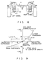
- the spring characteristic (relationship between load and deflection) of the gas spring is a nonlinear characteristic such that the greater the deflection on the contraction side, the greater the spring constant will be, as shown in Fig. 9.
- the respective absolute values of load increment +W on the outside of the turning movement of the vehicle and load decrement -W on the inside are equal. Accordingly, deflection L1 of the outside suspension assembly is not equal to deflection L2 of the inside suspension assembly (L1 ⁇ L2).
- the object of the present invention is to provide an anti-roll system, capable of restraining rolling during a turning movement of a vehicle and of preventing the center of gravity from rising during the turning movement.
- An anti-roll system provided by the inventors hereof has advantages such that it can keep the body of a vehicle substantially horizontal while the vehicle body is turning, can prevent the center of gravity of the vehicle body from rising during the turning movement, and can ensure higher running stability of the vehicle than the conventional anti-roll systems.
- the system according to the present invention is an anti-roll system according to one of claims 1, 5, and 9 Preferred embodiments thereof are described in the dependent claims.
- Anti-roll system 1 shown in Fig. 1 comprises hydropneumatic suspension assembly 2 for a left wheel and hydropneumatic suspension assembly 3 for a right wheel.
- Suspension assemblies 2 and 3 each include cylinder 5 and rod 6 inserted therein for movement in the axial direction thereof.
- Oil chamber 7 filled with oil and gas chamber 8 charged with an inert gas, such as nitrogen.
- the gas charging pressure is adjusted to a high level (e.g., 80 kgf/cm2) such that the tare of the body of a vehicle and movable load can be supported by only the repulsive force of gas.
- Chambers 7 and 8 are divided by means of partition member 9 which is composed of metallic bellows 9a capable of axial expansion and contraction.
- the gas pressure inside gas chamber 8 acts on oil chamber 7 through member 9, so that it urges rod 6 to be forced out of cylinder 5.
- Piston portion 10 formed at an end of rod 6 inside oil chamber 7.
- the lower end of cylinder 5 is connected to a wheel-side member by means of connecting portion 11.
- the upper end of rod 6 is connected to a body-side member.
- Height sensor 12 composed of a potentiometer, is used to detect the axial position of rod 6 relative to cylinder 5, that is, the height of the suspension assembly.
- Damping force generating mechanism 13, which is provided at piston portion 10, has an orifice.
- Hydraulic pipe 15 is connected to oil chamber 7. It is connected to oil tank 17 through oil discharging valve 16a (16b) for use as an example of oil discharging means. Pipe 15 is also connected to hydraulic pump 20, as a hydraulic source, and accumulator 20a through oil supplying valve 18a (18b) for use as an example of oil supplying means. Valves 16a (16b) and 18a (18b) are operated by means of a solenoid. Seal portion 21 between cylinder 5 and rod 6 communicates with oil tank 17 by means of drain pipe 22.
- Oil chambers 7, 7 of suspension assemblies 2 and 3 are connected, respectively, to sub-tanks 26 and 27 through oil passages 23a and 23b and solenoid valves 24 and 25 for spring constant switching.
- Sub-tanks 26 and 27, for use as accumulating means have oil chambers 30 and 31 and gas chambers 32 and 33, respectively, therein.
- Oil chambers 30 and 31 are completely divided from their corresponding gas chambers 32 and 33 by means of partition members 34 and 35, respectively, each composed of a metallic bellows.
- Chambers 32 and 33 are charged with a compressed inert gas, such as nitrogen. The gas charging pressure is equal to the gas pressure inside gas chamber 8.
- Cylinder 40 comprises symmetrical housing 41, piston 42 axially movable inside the housing, and detector 43 for detecting the axial position of the piston.
- the inside of housing 41 is divided into left and right oil chambers 45 and 46 by means of piston 42.
- Left chamber 45 communicates with oil chamber 7 of left-wheel suspension assembly 2 by means of oil passage 38.
- Right chamber 46 communicates with oil chamber 7 of right-wheel suspension assembly 3 by means of oil passage 39.
- Left and right control oil chambers 48 and 49 are disposed inside piston 42.
- Piston 42 is moved in the horizontal direction of Fig. 1 inside cylinder 41 by means of servo mechanism 54, which is composed of servo valve 51, hydraulic pipes 52 and 53, etc.
- servo mechanism 54 which is composed of servo valve 51, hydraulic pipes 52 and 53, etc.
- oil pressure accumulated in accumulator 20a acts on left or right control oil chamber 48 or 49, so that piston 42 moves in the direction of the oil pressure.
- Servo mechanism 54 is controlled by means of controller 57 which is formed of a microcomputer. Controller 57 is connected electrically with steering angle sensor 58 for detecting the operation angle of a steering wheel, and speed sensor 59 for detecting the running speed of the vehicle. Output signals from sensors 58 and 59 are supplied to controller 57. In controller 57, the size of a centrifugal force produced by a turning movement is automatically calculated on the basis of the relationship between the operation angle of the steering wheel and the vehicle speed, following a previously programmed procedure. A signal from height sensor 12 is also supplied to controller 57.
- Fig. 3 shows measured data on the centrifugal force produced when the vehicle, running at a speed of 50 km per hour, turns in an arc of a circle with a radius of about 10 m.
- peak G MAX of the centrifugal force appears about 5 seconds after the start of the turning movement.
- servo valve 51 When the vehicle turns to the left, for example, the turning state is detected by sensors 58 and 59, servo valve 51 is driven to the right of Fig. 1 in response to a command from controller 57. Thereupon, the oil pressure of accumulator 20a acts on right control oil chamber 49, so that piston 42 moves toward right oil chamber 46. As a result, the oil in chamber 46 is supplied to oil chamber 7 of outside suspension assembly 3, and at the same time, the same amount of oil from inside suspension assembly 2 flows into left oil chamber 45.
- the outside suspension assembly deflects by + ⁇ in a contracting direction for load increment +W, while the inside suspension assembly deflects by - ⁇ in an expanding direction for load decrement -W.
- the deflections of left and right suspension assemblies 2 and 3 have substantially the same absolute value
- anti-roll cylinder 40 is driven only when the turning extent, that is, the size of the centrifugal force, exceeds a certain limit. More specifically, the size of the centrifugal force during the turning movement is calculated in response to detection values delivered from steering sensor 58 and speed sensor 59 to controller 57, and the calculated value is compared with a previously inputted reference value. If the difference between the calculated value and the reference value is within predetermined limits, piston 42 of anti-roll cylinder 40 is held in a neutral position, and anti-roll control cannot be performed.
- servo valve 51 is controlled in accordance with the size of the centrifugal force, so that the greater the centrifugal force, the greater is the stroke of piston 42.
- the stroke of piston 42 is detected by detector 43, and fed back to controller 57.
- system 1 of the present embodiment if spring constant switching valves 24 and 25 of suspension assemblies 2 and 3 are simultaneously opened while the vehicle is running straight ahead, the spring constant of the suspension assemblies lowers, so that the comfortableness of the vehicle to ride in is improved. Also, the spring constant can be increased by simultaneously closing valves 24 and 25 during the straight running.
- Two or more sub-tanks may be connected to each of suspension assemblies 2 and 3.
- second tanks 26′ and 27′ may be additionally used.
- second spring constant switching valves 24′ and 25′ are additionally disposed between sub-tanks 26′ and 27′ and first sub-tanks 26 and 27, respectively.
- first valves 24 and 25 second valves 24′ and 25′ are controlled by means of controller 57.
- three spring characteristics can be obtained, as indicated by full line, broken line, and two-dot chain line in Fig. 2.
- Fig. 4 shows a second embodiment of the present invention.
- oil chambers 7, 7 of suspension assemblies 2 and 3 are connected to anti-roll cylinder 40 through by-pass control valves 36 and 37, respectively.
- the system of the second embodiment is operated as follows.
- piston 42 of anti-roll cylinder 40 goes on moving to the right of Fig. 4 during the time interval between the start and the peak (near G MAX in Fig. 3) of the turning movement.
- some of the oil is discharged from inside suspension assembly 2, while the oil is supplied to outside suspension assembly 3.
- outside by-pass control valve 37 is closed, while spring constant switching valve 25 is opened.
- Valves 24 and 25 and by-pass control valves 36 and 37 may be simple switching valves. Alternatively, however, flow regulating valves may be used for the purpose so that the flow quantity per unit time can be adjusted.
- Fig. 5 shows a third embodiment of the present invention.
- the object of the invention is achieved by controlling oil discharging valves 16a and 16b and oil supplying valves 18a and 18b during the turning movement of the vehicle.
- the system of the third embodiment is operated as follows.
- height h of inside suspension assembly 2 is compared with neutral height N , as shown in Fig. 7. If h is smaller N, oil supplying valve 18a is opened, so that the oil is supplied to inside suspension assembly 2.
Landscapes
- Engineering & Computer Science (AREA)
- Mechanical Engineering (AREA)
- Vehicle Body Suspensions (AREA)
Description
- The present invention relates to an anti-roll system for stabilizing the orientation of the body of a vehicle, such as an automobile, while the vehicle is changing its course or running along a curve of a road.
- As shown in Fig. 8, a pair of
hydropneumatic suspension assemblies cylinder rod oil chamber gas chamber gas chambers rods cylinders rod 105 ofinside suspension assembly 101 is reduced, while a load bearing onrod 106 ofoutside suspension assembly 102 increases. The respective absolute values of decrement -W of the load produced on the inside and increment +W of the load produced on the outside are substantially equal. - Thus, in
outside suspension assembly 102, the compressed gas ingas chamber 110 is further compressed corresponding to the load increment, so that the length of projection ofrod 106 fromcylinder 104 is reduced. Ininside suspension assembly 101 on the other hand, the length of projection ofrod 105 increases for the load decrement. In this state, therefore, the vehicle body tilts considerably in the transverse direction. - As means for restraining such a rolling effect, anti-roll systems are disclosed in U.S. Pat. No. 3,778,081 and Published Unexamined Japanese Utility Model Application No. 62-137812 (issued by the Japan Patent Office). In these prior art systems,
oil chambers oil passage 115, andanti-roll cylinder 116 is provided in the middle ofpassage 115, as shown in Fig. 8. When the vehicle turns to the left, for example, some of the oil is discharged from insidesuspension assembly 107 byanti-roll cylinder 116, and the same amount of oil is supplied tooutside oil chamber 108, so that the vehicle body is restrained from rolling. Thus, the capacity of insidegas chamber 109 increases by +α, while that ofoutside gas chamber 110 decreases by -α, as compared with the values obtained before turning movement. - A study made by the inventors hereof revealed that the conventional anti-roll systems are subject to the following drawbacks.
-
Gas chambers - Since the amount of oil discharged from the inside suspension assembly by
anti-roll cylinder 116 during the turning movement is equal to the amount of oil supplied to the outside suspension assembly, the respective absolute values of decrement -δ of the deflection of the inside suspension assembly and increment +δ of the deflection of the outside suspension assembly are equal. These suspension assemblies have nonlinear characteristics such that their spring constant increases in proportion to the deflection on the contraction side. These various factors indicate that the heights of the left and right suspension assemblies become actually equal when the height of each suspension assembly is greater by H than the value obtained before the turning movement. More specifically, deflection L1 of the outside suspension assembly in the contracting direction is smaller by H than δ, while deflection L2 of the inside suspension assembly in the expanding direction is greater by H than δ. Accordingly, the position of the center of gravity of the vehicle body during the turning movement is higher by H than the height reached before the turning movement, so that the running stability of the vehicle is poor. - Accordingly, the object of the present invention is to provide an anti-roll system, capable of restraining rolling during a turning movement of a vehicle and of preventing the center of gravity from rising during the turning movement.
- An anti-roll system provided by the inventors hereof has advantages such that it can keep the body of a vehicle substantially horizontal while the vehicle body is turning, can prevent the center of gravity of the vehicle body from rising during the turning movement, and can ensure higher running stability of the vehicle than the conventional anti-roll systems.
- The system according to the present invention is an anti-roll system according to one of
claims - This invention can be more fully understood from the following detailed description when taken in conjunction with the accompanying drawings, in which:
- Fig. 1 shows a hydraulic system of an anti-roll system according to a first embodiment of the present invention;
- Fig. 2 is a diagram showing the relationship between the load and deflection of a suspension assembly shown in Fig. 1;
- Fig. 3 is a diagram showing change of a centrifugal force during a turning movement of a vehicle;
- Fig. 4 shows a hydraulic system arrangement of an anti-roll system according to a second embodiment of the present invention;
- Fig. 5 shows a hydraulic system arrangement of an anti-roll system according to a third embodiment of the present invention;
- Fig. 6 is a flow chart illustrating the way valves operate when the centrifugal force increases in the system shown in Fig. 5;
- Fig. 7 is a flow chart illustrating the way the valves operate when the centrifugal force decreases in the system shown in Fig. 5;
- Fig. 8 shows an outline of a prior art anti-roll system; and
- Fig. 9 is a diagram showing the relationship between the load and the deflection of hydropneumatic suspension assemblies.
-
Anti-roll system 1 shown in Fig. 1 compriseshydropneumatic suspension assembly 2 for a left wheel andhydropneumatic suspension assembly 3 for a right wheel.Suspension assemblies cylinder 5 androd 6 inserted therein for movement in the axial direction thereof. Arranged insidecylinder 5 areoil chamber 7 filled with oil andgas chamber 8 charged with an inert gas, such as nitrogen. The gas charging pressure is adjusted to a high level (e.g., 80 kgf/cm²) such that the tare of the body of a vehicle and movable load can be supported by only the repulsive force of gas.Chambers partition member 9 which is composed ofmetallic bellows 9a capable of axial expansion and contraction. The gas pressure insidegas chamber 8 acts onoil chamber 7 throughmember 9, so that it urgesrod 6 to be forced out ofcylinder 5. - Piston
portion 10 formed at an end ofrod 6 insideoil chamber 7. The lower end ofcylinder 5 is connected to a wheel-side member by means of connectingportion 11. The upper end ofrod 6 is connected to a body-side member.Height sensor 12, composed of a potentiometer, is used to detect the axial position ofrod 6 relative tocylinder 5, that is, the height of the suspension assembly. Dampingforce generating mechanism 13, which is provided atpiston portion 10, has an orifice. Whencylinder 5 androd 6 are caused to move relatively to each other in the vertical direction by the roughness of a road surface, for example,gas chamber 8 increases or decreases its capacity, thereby absorbing a shock. As oil flows throughmechanism 13, moreover, the motion ofrod 6 is damped. -
Hydraulic pipe 15 is connected tooil chamber 7. It is connected tooil tank 17 through oil discharging valve 16a (16b) for use as an example of oil discharging means. Pipe 15 is also connected tohydraulic pump 20, as a hydraulic source, and accumulator 20a through oil supplying valve 18a (18b) for use as an example of oil supplying means. Valves 16a (16b) and 18a (18b) are operated by means of a solenoid.Seal portion 21 betweencylinder 5 androd 6 communicates withoil tank 17 by means ofdrain pipe 22. -
Oil chambers suspension assemblies sub-tanks oil passages solenoid valves Sub-tanks oil chambers gas chambers Oil chambers corresponding gas chambers partition members gas chamber 8. - Paired suspension assemblies 2 and 3, constructed in this manner, are connected to
anti-roll cylinder 40 by means ofoil passages Cylinder 40 comprisessymmetrical housing 41,piston 42 axially movable inside the housing, anddetector 43 for detecting the axial position of the piston. The inside ofhousing 41 is divided into left andright oil chambers piston 42.Left chamber 45 communicates withoil chamber 7 of left-wheel suspension assembly 2 by means ofoil passage 38.Right chamber 46 communicates withoil chamber 7 of right-wheel suspension assembly 3 by means ofoil passage 39. Left and rightcontrol oil chambers piston 42. -
Piston 42 is moved in the horizontal direction of Fig. 1 insidecylinder 41 by means ofservo mechanism 54, which is composed ofservo valve 51,hydraulic pipes servo valve 51, oil pressure accumulated in accumulator 20a acts on left or rightcontrol oil chamber piston 42 moves in the direction of the oil pressure. -
Servo mechanism 54 is controlled by means ofcontroller 57 which is formed of a microcomputer.Controller 57 is connected electrically withsteering angle sensor 58 for detecting the operation angle of a steering wheel, andspeed sensor 59 for detecting the running speed of the vehicle. Output signals fromsensors controller 57. Incontroller 57, the size of a centrifugal force produced by a turning movement is automatically calculated on the basis of the relationship between the operation angle of the steering wheel and the vehicle speed, following a previously programmed procedure. A signal fromheight sensor 12 is also supplied tocontroller 57. - The following is description of the operation of
anti-roll system 1 with the aforementioned construction. - When the vehicle turns to run along a curve or change its course, the vehicle body is subjected to a transverse centrifugal force. Fig. 3 shows measured data on the centrifugal force produced when the vehicle, running at a speed of 50 km per hour, turns in an arc of a circle with a radius of about 10 m. In this example, peak GMAX of the centrifugal force appears about 5 seconds after the start of the turning movement.
- When the vehicle turns to the left, for example, the turning state is detected by
sensors servo valve 51 is driven to the right of Fig. 1 in response to a command fromcontroller 57. Thereupon, the oil pressure of accumulator 20a acts on rightcontrol oil chamber 49, so thatpiston 42 moves towardright oil chamber 46. As a result, the oil inchamber 46 is supplied tooil chamber 7 ofoutside suspension assembly 3, and at the same time, the same amount of oil frominside suspension assembly 2 flows intoleft oil chamber 45. - As spring
constant switching valve 25 betweenoutside suspension assembly 3 andsub-tank 27 opens, moreover,oil chambers chambers gas chamber 8 ofsuspension assembly 3 andgas chamber 33 ofsub-tank 27 cooperate as gas spring means. As a result, the spring constant ofoutside suspension assembly 3 lowers, as indicated by a broken-line curve in Fig. 2. Since springconstant switching valve 24 ofinside suspension assembly 2 is kept closed, on the other hand, the spring constant ofsuspension assembly 2 is kept in the state before the turning, that is, the characteristic indicated by a full-line curve in Fig. 2 is maintained forsuspension assembly 2. Since there is such a difference between the spring characteristics of the inside and outside suspension assemblies, the outside suspension assembly deflects by +δ in a contracting direction for load increment +W, while the inside suspension assembly deflects by -δ in an expanding direction for load decrement -W. Thus, the deflections of left andright suspension assemblies suspension assemblies - When the vehicle turns to the right, on the other hand,
piston 42 ofanti-roll cylinder 40 is moved to the left of Fig. 1. As a result, the oil is supplied tooil chamber 7 of left-wheel suspension assembly 2, while some of the oil in right-wheel suspension assembly 3 is discharged. As springconstant switching valve 24 ofsuspension assembly 2 is opened,gas chamber 8 ofoutside suspension assembly 2 andgas chamber 32 ofsub-tank 26 cooperate with each other. Thus, the spring constant ofsuspension assembly 2 lowers, so that the heights ofsuspension assemblies - In
system 1 of the present embodiment,anti-roll cylinder 40 is driven only when the turning extent, that is, the size of the centrifugal force, exceeds a certain limit. More specifically, the size of the centrifugal force during the turning movement is calculated in response to detection values delivered from steeringsensor 58 andspeed sensor 59 tocontroller 57, and the calculated value is compared with a previously inputted reference value. If the difference between the calculated value and the reference value is within predetermined limits,piston 42 ofanti-roll cylinder 40 is held in a neutral position, and anti-roll control cannot be performed. If the difference between the calculated value and the reference value exceeds the predetermined limits,servo valve 51 is controlled in accordance with the size of the centrifugal force, so that the greater the centrifugal force, the greater is the stroke ofpiston 42. The stroke ofpiston 42 is detected bydetector 43, and fed back tocontroller 57. - In
system 1 of the present embodiment, if springconstant switching valves suspension assemblies valves - Two or more sub-tanks may be connected to each of
suspension assemblies second tanks 26′ and 27′ may be additionally used. In this case, second springconstant switching valves 24′ and 25′ are additionally disposed betweensub-tanks 26′ and 27′ and first sub-tanks 26 and 27, respectively. Likefirst valves second valves 24′ and 25′ are controlled by means ofcontroller 57. In this case, three spring characteristics can be obtained, as indicated by full line, broken line, and two-dot chain line in Fig. 2. - In this case, when the vehicle turns to the right to a relatively large extent or with a great centrifugal force, for example, the spring characteristic of
outside suspension assembly 2 is switched to the one indicated by two-dot chain line in Fig. 2 by opening both springconstant switching valves suspension assembly 2. Since springconstant switching valves inside suspension assembly 3 is kept closed,suspension assembly 3 enjoys the spring constant indicated by full line in Fig. 2, without regard to the extent of the turning movement. If the extent of the turning movement is small or if the centrifugal force is small, on the other hand, the spring constant ofoutside suspension assembly 2 is switched to the one indicated by broken line in Fig. 2. Thus, by increasing the sub-tanks and the spring constant switching valves in number, more appropriate anti-roll control can be effected, depending on the centrifugal force during the turning movement. - Fig. 4 shows a second embodiment of the present invention. In this embodiment,
oil chambers suspension assemblies anti-roll cylinder 40 through by-pass control valves - The system of the second embodiment is operated as follows. When the vehicle turns to the left, for example,
piston 42 ofanti-roll cylinder 40 goes on moving to the right of Fig. 4 during the time interval between the start and the peak (near GMAX in Fig. 3) of the turning movement. As a result, some of the oil is discharged frominside suspension assembly 2, while the oil is supplied tooutside suspension assembly 3. If the height ofsuspension assembly 3 exceeds a neutral position, outside by-pass control valve 37 is closed, while springconstant switching valve 25 is opened. By doing this, all the extra oil that is fed fromanti-roll cylinder 40 tooutside suspension assembly 3 after the neutral height is reached bysuspension assembly 3 flows intosub-tank 27 ofsuspension assembly 3. Since inside by-pass control valve 36 is kept open, the oil continues to be discharged frominside suspension assembly 2 while the centrifugal force is increasing, andsuspension assembly 2 is kept at a predetermined height. If the pressure receiving surface area is S, volume V of the oil introduced intosub-tank 27 is given by

Valve 25, like by-pass control valve 37, may be normally open. Ifvalves anti-roll cylinder 40 tooutside suspension assembly 3 after the start of the turning movement starts to flow also intosub-tank 27. In this case, therefore, only by-pass control valve 37 is closed whenoutside suspension assembly 3 is caused to exceed the neutral height by the oil fed fromcylinder 40. - When the left-handed turning movement is past its peak so that the centrifugal force starts to be reduced, the oil in
sub-tank 27 is returned toanti-roll cylinder 40 throughoil passage 39 by the gas pressure insidesub-tank 27. As by-pass control valve 37 is opened, moreover, some of the oil is returned fromoutside suspension assembly 3 to controlcylinder 40. Thus, left andright suspension assemblies -
Valves pass control valves - Fig. 5 shows a third embodiment of the present invention. In this embodiment, the object of the invention is achieved by controlling
oil discharging valves 16a and 16b andoil supplying valves 18a and 18b during the turning movement of the vehicle. The system of the third embodiment is operated as follows. - When the vehicle turns to the left, for example,
piston 42 ofanti-roll cylinder 40 moves towardright oil chamber 46, as in the case of the foregoing embodiments. Thereupon, the oil is supplied tooutside suspension assembly 3 so that the heights of left andright suspension assemblies inside suspension assembly 2. In the present embodiment, height h ofinside suspension assembly 2 is compared with neutral height N, as shown in Fig. 6, while the centrifugal force is increasing after the start of the turning movement. If exceeds N, oil discharging valve 16a is opened, so that the oil is discharged frominside suspension assembly 2. When the turning movement is past its peak so that the centrifugal force starts to be reduced, height h ofinside suspension assembly 2 is compared with neutral height N, as shown in Fig. 7. If h is smaller N, oil supplying valve 18a is opened, so that the oil is supplied toinside suspension assembly 2. - When the vehicle turns to the right,
piston 42 ofanti-roll cylinder 40 is driven in the opposite direction, in contrast with the case of the left-handed turning movement. Thereupon, the oils is fed intooil chamber 7 of left-wheel suspension assembly 2, while some of the oil in right-wheel suspension assembly 3 is discharged. Before the peak of the turning movement is reached,oil discharging valve 16b is controlled so that the height ofinside suspension assembly 2 does not exceeds the neutral height, as shown in Fig. 6. When the turning movement is past its peak so that the centrifugal force starts to be reduced,oil supplying valve 18b is controlled so that the height ofinside suspension assembly 2 never becomes lower than the neutral height, as shown in Fig. 7. Thus, the vehicle height can be kept constant, the center of gravity of the vehicle body can be prevented from rising.
Claims (11)
- An anti-roll system (1) for stabilizing the orientation of the body of a vehicle while the vehicle is turning, comprising:
a pair of hydropneumatic suspension assemblies (2, 3) each including a cylinder (5) and a rod (6) inserted therein, each said suspension assembly (2, 3) having an oil chamber (7) containing oil and a gas chamber (8) charged with compressed gas and having a nonlinear spring characteristic such that the spring constant of the suspension assembly (2, 3) increases as the suspension assembly (2, 3) deflects in the direction moving the rod (6) into the cylinder (5); and
detecting means (58, 59) for detecting a turning condition of the vehicle
an anti-roll cylinder (40) connected to the paired suspension assemblies (2, 3) and adapted to discharge some of the oil from the inside suspension assembly to supply oil to the outside suspension assembly so that the heights of the two suspension assemblies (2, 3) are equal when the vehicle is detected to be in a turning condition
characterized by further comprising:
accumulating means (26, 26', 27, 27') connected to each said suspension assembly (2, 3) and having a gas chamber (32, 33) defined therein, said gas chamber (32, 33) containing a compressed gas; and
spring constant switching means (24, 24', 25, 25') disposed between the suspension assemblies (2, 3) and the accumulating means (26, 26', 27, 27') corresponding thereto, each of said switching means (24, 24', 25, 25') being adapted to operate such that the outside suspension is caused to communicate with the accumulating means (26, 26', 27, 27'), thereby causing the gas chamber (8) of the outside suspension and the gas chamber (32, 33) of the accumulating means (26, 26', 27, 27') to cooperate with each other, when the vehicle is detected to be in a turning condition. - The anti-roll system (1) according to claim 1, characterized in that each of said suspension assembly (2, 3) is provided with first accumulating means (26, 27), first spring constant switching means (24, 25), second accumulating means (26', 27'), and second spring constant switching means (24', 25'), so that only the first spring constant switching means (24, 25) is operated so that the outside suspension assembly communicates with only the first accumulating means (26, 27) when the vehicle turns slightly, and that the first and second spring constant switching means (24, 24', 25, 25') are operated so that the outside suspension assembly communicates with both the first and second accumulating means (26, 26', 27, 27') when the vehicle turns sharply.
- The anti-roll system (1) according to claim 1, characterized in that the detecting means (58, 59) comprises a sensor (58) for detecting the angle of the steering wheel when the vehicle turns, a sensor (59) for detecting the speed of the vehicle, and a controller (57) supplied with detection signals delivered from the sensors (58, 59) and a reference value for the height of each said suspension assembly (2, 3), said controller (57) being adapted to calculate the size of the centrifugal force produced during the turning movement on the basis of the relationship between the steering angle and the vehicle speed detected by means of the sensors (58, 59), and to actuate the anti-roll cylinder (40) only when the calculated value exceeds the reference value.
- The anti-roll system (1) according to claim 1, characterized by further comprising a height sensor (12) for detecting the height of each said suspension assembly (2, 3), a controller (57) supplied with a signal delivered from the height sensor (12), and a servo mechanism (54) for driving the anti-roll cylinder (40) in response to a signal delivered from the controller (57), said controller (57) being adapted to operate the servo mechanism (54) in a direction such that the heights of the suspension assemblies (2, 3) of both the left and right wheels are equal, in response to a height signal delivered from the sensor (12).
- An anti-roll system (1) for stabilizing the orientation of the body of a vehicle while the vehicle is turning, comprising:
a pair of hydropneumatic suspension assemblies (2, 3) each including a cylinder (5) and a rod (6) inserted therein, each said suspension assembly (2, 3) having an oil chamber (7) containing oil and a gas chamber (8) charged with compressed gas and having a nonlinear spring characteristic such that the spring constant of the suspension assembly (2, 3) increases as the suspension assembly (2, 3) deflects in the direction moving the rod (6) into the cylinder (5); and
sensor means (58, 59) for detecting the centrifugal force acting on the vehicle when the vehicle is turning;
an anti-roll cylinder (40) connected to the paired suspension assemblies (2, 3) and adapted to discharge some of the oil from the inside suspension assembly to supply oil to the outside suspension assembly so that the heights of the two suspension assemblies (2, 3) are equal when the vehicle is detected to be in a turning condition;
oil passages (38, 39) connecting oil chambers (7) of the paired suspension assemblies (2, 3) and the anti-roll cylinder (40);
characterized by further comprising:
accumulating means (26, 27) connected to each said suspension assembly (2, 3) and having a gas chamber (32, 33) defined therein, said gas chamber (32, 33) containing a compressed gas;
bypass control means (36, 37) disposed in each of said oil passages (36, 37), and adapted to disconnect the oil chamber (7) of the outside suspension assembly from the anti-roll cylinder (40), thereby causing the oil from the anti-roll cylinder (40) to flow into the accumulating means (26, 27), after the height of the outside suspension assembly is caused to attain a reference height by the oil from the anti-roll cylinder (40), while the centrifugal force detected by said sensor means (58, 59) during the turning movement of the vehicle is increasing, and to connect the oil chamber (7) of the outside suspension assembly with the anti-roll cylinder (40), thereby causing the oil to flow from the outside suspension assembly into the anti-roll cylinder (40), while the centrifugal force is decreasing after a peak in the turning movement has been detected. - The anti-roll system (1) according to claim 5, characterized in that the detecting means (58, 59) comprises a sensor (58) for detecting the angle of the steering wheel when the vehicle turns, a sensor (59) for detecting the speed of the vehicle, and a controller (57) supplied with detection signals delivered from the sensors (58, 59) and a reference value for the height of each said suspension assembly (2, 3), said controller (57) being adapted to calculate the size of the centrifugal force produced during the turning movement on the basis of the relationship between the steering angle and the vehicle speed detected by means of the sensors (58, 59), and to actuate the anti-roll cylinder (40) only when the calculated value exceeds the reference value.
- The anti-roll system (1) according to claim 5, characterized by further comprising a height sensor (12) for detecting the height of each said suspension assembly (2, 3), a controller (57) supplied with a signal delivered from the height sensor (12), and a servo mechanism (54) for driving the anti-roll cylinder (40) in response to a signal delivered from the controller (57), said controller (57) being adapted to operate the servo mechanism (54) in a direction such that the heights of the suspension assemblies (2, 3) of both the left and right wheels are equal, in response to a height signal delivered from the sensor (12).
- The anti-roll system (1) according to claim 5, characterized in that said bypass control means (36, 37) includes a flow regulating valve whose opening is adjustable.
- An anti-roll system (1) for stabilizing the orientation of the body of a vehicle while the vehicle is turning, comprising:
a pair of hydropneumatic suspension assemblies (2, 3) each including a cylinder (5) and a rod (6) inserted therein, each said suspension assembly (2, 3) having an oil chamber (7) containing oil and a gas chamber (8) charged with compressed gas and having a nonlinear spring characteristic such that the spring constant of the suspension assembly (2, 3) increases as the suspension assembly (2, 3) deflects in the direction moving the rod (6) into the cylinder (5);
sensor means (58, 59) for detecting the centrifugal force acting on the vehicle when the vehicle is turning
an anti-roll cylinder (40) connected to the paired suspension assemblies (2, 3) and adapted to discharge some of the oil from the inside suspension assembly to supply oil to the outside suspension assembly so that the heights of the two suspension assemblies (2, 3) are equal when the vehicle is detected to be in a turning condition;
characterized by further comprising:
oil discharging means (16a, 16b) connected to the suspension assemblies (2, 3) and adapted to continue discharging the oil from the inside suspension so that the height of the inside suspension assembly prior to the turning movement is maintained, while the centrifugal force produced during the turning movement of the vehicle is increasing; and
oil supplying means (18a, 18b) connected to the suspension assemblies (2, 3) and adapted to continue supplying the oil to the inside suspension so that the height of the inside suspension assembly prior to the turning movement is maintained, while the centrifugal force is decreasing after a peak in the turning movement has been detected. - The anti-roll system (1) according to claim 9, characterized in that the detecting means (58, 59) comprises a sensor (58) for detecting the angle of the steering wheel when the vehicle turns, a sensor (59) for detecting the speed of the vehicle, and a controller (57) supplied with detection signals delivered from the sensors (58, 59) and a reference value for the height of each said suspension assembly (2, 3), said controller (57) being adapted to calculate the size of the centrifugal force produced during the turning movement on the basis of the relationship between the steering angle and the vehicle speed detected by means of the sensors (58, 59), and to actuate the anti-roll cylinder (40) only when the calculated value exceeds the reference value.
- The anti-roll system (1) according to claim 9, characterized by further comprising a height sensor (12) for detecting the height of each said suspension assembly (2, 3), a controller (57) supplied with a signal delivered from the height sensor (12), and a servo mechanism (54) for driving the anti-roll cylinder (40) in response to a signal delivered from the controller (57), said controller (57) being adapted to operate the servo mechanism (54), the oil discharging means (16a, 16b), and the oil supplying means (18a, 18b) in a direction such that the heights of the suspension assemblies (2, 3) of both the left and right wheels are equal, in response to a height signal delivered from the sensor (12).
Applications Claiming Priority (6)
| Application Number | Priority Date | Filing Date | Title |
|---|---|---|---|
| JP211387/88 | 1988-08-25 | ||
| JP211389/88 | 1988-08-25 | ||
| JP21138988A JP2625166B2 (en) | 1988-08-25 | 1988-08-25 | Anti-rolling device for vehicles |
| JP211388/88 | 1988-08-25 | ||
| JP21138888A JP2625165B2 (en) | 1988-08-25 | 1988-08-25 | Anti-rolling device for vehicles |
| JP21138788A JP2625164B2 (en) | 1988-08-25 | 1988-08-25 | Anti-rolling device for vehicles |
Publications (3)
| Publication Number | Publication Date |
|---|---|
| EP0355715A2 EP0355715A2 (en) | 1990-02-28 |
| EP0355715A3 EP0355715A3 (en) | 1991-04-03 |
| EP0355715B1 true EP0355715B1 (en) | 1993-11-18 |
Family
ID=27329238
Family Applications (1)
| Application Number | Title | Priority Date | Filing Date |
|---|---|---|---|
| EP89115188A Expired - Lifetime EP0355715B1 (en) | 1988-08-25 | 1989-08-17 | Vehicular anti-roll system for stabilizing the orientation of a vehicle body |
Country Status (3)
| Country | Link |
|---|---|
| US (1) | US4993744A (en) |
| EP (1) | EP0355715B1 (en) |
| DE (1) | DE68910752T2 (en) |
Families Citing this family (9)
| Publication number | Priority date | Publication date | Assignee | Title |
|---|---|---|---|---|
| JP2530372B2 (en) * | 1989-08-28 | 1996-09-04 | トヨタ自動車株式会社 | Suspension pressure controller |
| FR2677306A1 (en) * | 1991-06-07 | 1992-12-11 | Peugeot | ANTI-ROLLING DEVICE FOR THE AXLE OF A HYDROPNEUMATIC SUSPENSION VEHICLE. |
| US5383680A (en) * | 1992-12-21 | 1995-01-24 | Cadillac Gage Textron Inc. | Anti-roll system for wheeled vehicles |
| DE19505712C2 (en) * | 1995-02-20 | 2002-03-14 | Mowag Motorwagenfabrik Ag Kreu | Height adjustable, hydropneumatic suspension |
| US5785344A (en) * | 1996-01-22 | 1998-07-28 | Tenneco Automotive Inc. | Active roll control |
| US20060076741A1 (en) * | 2000-11-22 | 2006-04-13 | Lim Howard T S | Vehicle stability system: using active tilting mechanism as a counter measure to natural tilt |
| US7063334B2 (en) * | 2000-11-22 | 2006-06-20 | Howard Tak Su Lim | Vehicle stability system using active tilting mechanism |
| CN101070046B (en) * | 2006-12-06 | 2010-12-01 | 李忠德 | Automobile turning automatic balance system |
| US9573435B2 (en) * | 2013-09-29 | 2017-02-21 | Elka Suspension Inc. | Dual inline hydraulic device |
Family Cites Families (14)
| Publication number | Priority date | Publication date | Assignee | Title |
|---|---|---|---|---|
| JPS5121219B1 (en) * | 1971-05-12 | 1976-07-01 | ||
| JPS5128891A (en) * | 1974-09-05 | 1976-03-11 | Nippon Synthetic Chem Ind | ECHIRENNSAKUSANBINIRUKYOJUGOTAIKENKABUTSU NO SEIZOHO |
| US4620619A (en) * | 1982-05-20 | 1986-11-04 | Atsugi Motor Parts Co., Ltd. | Variable-damping-force shock absorber |
| US4491207A (en) * | 1983-07-15 | 1985-01-01 | Lord Corporation | Fluid control means for vehicle suspension system |
| AU553238B2 (en) * | 1983-09-26 | 1986-07-10 | Nhk Spring Co. Ltd. | Vehicle hydropneumatic suspension |
| JPS60119638A (en) * | 1983-11-30 | 1985-06-27 | Hitachi Maxell Ltd | Method and apparatus for manufacturing magnetic recording medium |
| JPS61122015A (en) * | 1984-11-19 | 1986-06-10 | Toyota Motor Corp | Suspension for car |
| US4607861A (en) * | 1984-12-17 | 1986-08-26 | General Motors Corporation | Hydraulic stabilizing system for vehicle suspension |
| FR2581596B1 (en) * | 1985-05-09 | 1989-12-08 | Peugeot | HYDRO-PNEUMATIC ANTI-ROLL |
| JPS62137812A (en) * | 1985-12-11 | 1987-06-20 | Kobe Steel Ltd | Atomized iron powder for dust core magnetic body |
| GB2186050B (en) * | 1986-01-30 | 1989-10-25 | Nhk Spring Co Ltd | Car suspension system |
| JPS62137812U (en) * | 1986-02-25 | 1987-08-31 | ||
| US4813519A (en) * | 1986-06-23 | 1989-03-21 | Nhk Spring Co., Ltd. | Cylinder piston apparatus for a suspension system |
| US4746106A (en) * | 1986-08-15 | 1988-05-24 | Nhk Spring Co., Ltd. | Car suspension system |
-
1989
- 1989-08-14 US US07/393,885 patent/US4993744A/en not_active Expired - Fee Related
- 1989-08-17 DE DE89115188T patent/DE68910752T2/en not_active Expired - Fee Related
- 1989-08-17 EP EP89115188A patent/EP0355715B1/en not_active Expired - Lifetime
Non-Patent Citations (1)
| Title |
|---|
| JP-U-62137812 * |
Also Published As
| Publication number | Publication date |
|---|---|
| US4993744A (en) | 1991-02-19 |
| EP0355715A2 (en) | 1990-02-28 |
| DE68910752D1 (en) | 1993-12-23 |
| DE68910752T2 (en) | 1994-04-14 |
| EP0355715A3 (en) | 1991-04-03 |
Similar Documents
| Publication | Publication Date | Title |
|---|---|---|
| US5087072A (en) | Attitude change suppressive control system for active suspension system for automotive vehicle | |
| EP0249246B1 (en) | Actively controlled automotive suspension system with adjustable rolling stability | |
| US5113345A (en) | System for controlling active suspensions of a vehicle | |
| KR920004520B1 (en) | Automotive Suspension Control | |
| US4743000A (en) | Method and apparatus for controlling spring stiffness, in particular in vehicles | |
| EP0286072B1 (en) | System supplying a hydraulic pressure variable with the operating condition of an automotive vehicle | |
| EP0249227B2 (en) | Actively controlled automotive suspension system with mutually independent hydraulic systems having mutually different damping characteristics for improving response characteristics in active suspension control | |
| EP0224036B1 (en) | System for vehicle height adjustment with steering angle change rate correction | |
| JPS62299418A (en) | Vehicle suspension control device | |
| US4872702A (en) | Suspension system for vehicles | |
| US7641208B1 (en) | Vehicle roll control system with self-centering actuator | |
| JPH0696363B2 (en) | Active suspension | |
| EP0345816A2 (en) | Anti-rolling control for actively controlled automotive suspension system with enhanced rolling detecting ability | |
| EP0725737A1 (en) | Vehicle suspension system | |
| US4900056A (en) | Hydraulic cylinder assembly for automotive suspension system and actively controlled suspension system utilizing same | |
| EP0311114B1 (en) | Actively controlled suspension system for automotive vehicles with vehicular speed dependent variable damping characteristics | |
| JPH03511A (en) | Car height control method for vehicle with car height adjuster | |
| US5016907A (en) | Anti-rolling control system for automotive active suspension system | |
| EP0189880A2 (en) | Rear suspension controller | |
| US4993744A (en) | Vehicular anti-roll system for stabilizing the orientation of a vehicle body | |
| US4722546A (en) | Rear suspension controller | |
| JPH0295910A (en) | Control device for automotive active suspension | |
| EP0315457B1 (en) | Suspension control apparatus and method for a vehicle | |
| EP0188284A2 (en) | Rear suspension controller | |
| JPH0813602B2 (en) | Suspension control device |
Legal Events
| Date | Code | Title | Description |
|---|---|---|---|
| PUAI | Public reference made under article 153(3) epc to a published international application that has entered the european phase |
Free format text: ORIGINAL CODE: 0009012 |
|
| 17P | Request for examination filed |
Effective date: 19890817 |
|
| AK | Designated contracting states |
Kind code of ref document: A2 Designated state(s): DE FR GB |
|
| PUAL | Search report despatched |
Free format text: ORIGINAL CODE: 0009013 |
|
| AK | Designated contracting states |
Kind code of ref document: A3 Designated state(s): DE FR GB |
|
| 17Q | First examination report despatched |
Effective date: 19920826 |
|
| GRAA | (expected) grant |
Free format text: ORIGINAL CODE: 0009210 |
|
| AK | Designated contracting states |
Kind code of ref document: B1 Designated state(s): DE FR GB |
|
| REF | Corresponds to: |
Ref document number: 68910752 Country of ref document: DE Date of ref document: 19931223 |
|
| ET | Fr: translation filed | ||
| PLBE | No opposition filed within time limit |
Free format text: ORIGINAL CODE: 0009261 |
|
| STAA | Information on the status of an ep patent application or granted ep patent |
Free format text: STATUS: NO OPPOSITION FILED WITHIN TIME LIMIT |
|
| 26N | No opposition filed | ||
| PGFP | Annual fee paid to national office [announced via postgrant information from national office to epo] |
Ref country code: FR Payment date: 19960717 Year of fee payment: 8 |
|
| PGFP | Annual fee paid to national office [announced via postgrant information from national office to epo] |
Ref country code: DE Payment date: 19960726 Year of fee payment: 8 |
|
| PGFP | Annual fee paid to national office [announced via postgrant information from national office to epo] |
Ref country code: GB Payment date: 19960808 Year of fee payment: 8 |
|
| PG25 | Lapsed in a contracting state [announced via postgrant information from national office to epo] |
Ref country code: GB Free format text: LAPSE BECAUSE OF NON-PAYMENT OF DUE FEES Effective date: 19970817 |
|
| GBPC | Gb: european patent ceased through non-payment of renewal fee |
Effective date: 19970817 |
|
| PG25 | Lapsed in a contracting state [announced via postgrant information from national office to epo] |
Ref country code: FR Free format text: LAPSE BECAUSE OF NON-PAYMENT OF DUE FEES Effective date: 19980430 |
|
| PG25 | Lapsed in a contracting state [announced via postgrant information from national office to epo] |
Ref country code: DE Free format text: LAPSE BECAUSE OF NON-PAYMENT OF DUE FEES Effective date: 19980501 |
|
| REG | Reference to a national code |
Ref country code: FR Ref legal event code: ST |