EP0354715B1 - Flow rate control system - Google Patents
Flow rate control system Download PDFInfo
- Publication number
- EP0354715B1 EP0354715B1 EP89307839A EP89307839A EP0354715B1 EP 0354715 B1 EP0354715 B1 EP 0354715B1 EP 89307839 A EP89307839 A EP 89307839A EP 89307839 A EP89307839 A EP 89307839A EP 0354715 B1 EP0354715 B1 EP 0354715B1
- Authority
- EP
- European Patent Office
- Prior art keywords
- ink
- error signal
- valve
- integral
- derivative
- Prior art date
- Legal status (The legal status is an assumption and is not a legal conclusion. Google has not performed a legal analysis and makes no representation as to the accuracy of the status listed.)
- Expired - Lifetime
Links
- 208000019300 CLIPPERS Diseases 0.000 claims abstract description 17
- 208000021930 chronic lymphocytic inflammation with pontine perivascular enhancement responsive to steroids Diseases 0.000 claims abstract description 17
- 238000000034 method Methods 0.000 claims description 18
- 230000008859 change Effects 0.000 claims description 15
- 238000001704 evaporation Methods 0.000 claims description 11
- 230000008020 evaporation Effects 0.000 claims description 11
- 230000000694 effects Effects 0.000 claims description 10
- 238000001914 filtration Methods 0.000 claims description 7
- 230000002401 inhibitory effect Effects 0.000 claims description 6
- 230000000670 limiting effect Effects 0.000 claims description 4
- 238000005259 measurement Methods 0.000 abstract description 3
- 239000000976 ink Substances 0.000 description 86
- 230000010355 oscillation Effects 0.000 description 9
- 238000010586 diagram Methods 0.000 description 8
- 230000009471 action Effects 0.000 description 6
- 238000012546 transfer Methods 0.000 description 6
- 230000008569 process Effects 0.000 description 5
- 230000004044 response Effects 0.000 description 5
- 230000010354 integration Effects 0.000 description 3
- 239000000758 substrate Substances 0.000 description 3
- 230000007423 decrease Effects 0.000 description 2
- 230000001934 delay Effects 0.000 description 2
- 239000012530 fluid Substances 0.000 description 2
- 238000007641 inkjet printing Methods 0.000 description 2
- 239000000203 mixture Substances 0.000 description 2
- 230000004048 modification Effects 0.000 description 2
- 238000012986 modification Methods 0.000 description 2
- 230000003534 oscillatory effect Effects 0.000 description 2
- 238000007639 printing Methods 0.000 description 2
- 230000003134 recirculating effect Effects 0.000 description 2
- 230000004075 alteration Effects 0.000 description 1
- 238000013459 approach Methods 0.000 description 1
- 230000009286 beneficial effect Effects 0.000 description 1
- 230000008901 benefit Effects 0.000 description 1
- 238000012937 correction Methods 0.000 description 1
- 230000003247 decreasing effect Effects 0.000 description 1
- 230000001419 dependent effect Effects 0.000 description 1
- 238000001514 detection method Methods 0.000 description 1
- 238000011161 development Methods 0.000 description 1
- 230000005484 gravity Effects 0.000 description 1
- 238000009499 grossing Methods 0.000 description 1
- 230000006872 improvement Effects 0.000 description 1
- 230000000977 initiatory effect Effects 0.000 description 1
- 230000001788 irregular Effects 0.000 description 1
- 230000010363 phase shift Effects 0.000 description 1
- 238000011084 recovery Methods 0.000 description 1
- 230000002829 reductive effect Effects 0.000 description 1
- 238000012552 review Methods 0.000 description 1
- 239000007787 solid Substances 0.000 description 1
- 239000002904 solvent Substances 0.000 description 1
- 230000001052 transient effect Effects 0.000 description 1
Images



Classifications
-
- B—PERFORMING OPERATIONS; TRANSPORTING
- B41—PRINTING; LINING MACHINES; TYPEWRITERS; STAMPS
- B41J—TYPEWRITERS; SELECTIVE PRINTING MECHANISMS, i.e. MECHANISMS PRINTING OTHERWISE THAN FROM A FORME; CORRECTION OF TYPOGRAPHICAL ERRORS
- B41J2/00—Typewriters or selective printing mechanisms characterised by the printing or marking process for which they are designed
- B41J2/005—Typewriters or selective printing mechanisms characterised by the printing or marking process for which they are designed characterised by bringing liquid or particles selectively into contact with a printing material
- B41J2/01—Ink jet
- B41J2/17—Ink jet characterised by ink handling
- B41J2/175—Ink supply systems ; Circuit parts therefor
-
- G—PHYSICS
- G05—CONTROLLING; REGULATING
- G05D—SYSTEMS FOR CONTROLLING OR REGULATING NON-ELECTRIC VARIABLES
- G05D7/00—Control of flow
- G05D7/06—Control of flow characterised by the use of electric means
- G05D7/0617—Control of flow characterised by the use of electric means specially adapted for fluid materials
- G05D7/0629—Control of flow characterised by the use of electric means specially adapted for fluid materials characterised by the type of regulator means
- G05D7/0635—Control of flow characterised by the use of electric means specially adapted for fluid materials characterised by the type of regulator means by action on throttling means
Definitions
- This invention relates to ink jet printing systems in general and to systems for maintaining satisfactory operation thereof in particular.
- Ink jet systems are generally known in this art and involve the use of electrically conductive ink compositions which are subjected to vibratory energy to create drops. The drops are then selectively charged for deflection by electrostatic plates onto a substrate to be marked. See, for example, United States Patent No. 4,555,712. Drops which are not directed at the substrate return to an ink reservoir for reuse. As the system operates, ink is lost through printing and evaporation. This, as well as the effects of temperature and other system variations, causes the ink flow rate to vary, sometimes considerably. To sustain printing operations over a long period it is necessary to monitor and control the ink flow rate.
- control systems monitor the change in flow rate over a period of operation and, responsive to detection of changes, alter the ink composition or add make-up ink thereby to keep the flow rate substantially constant.
- a typical action is to periodically operate a valve permitting the addition of make-up ink to the ink reservoir to compensate for the loss of solvent from the ink.
- the device described in the '712 patent uses a simple scheme for determining operation of the make-up ink valve. If the flow time measurement reading is greater than the set point time the valve is actuated for a fixed time duration. This occurs once each system cycle until the flow time is less than the set point time. In some instances, an average flow time over several cycles is compared to the set point.
- Oscillations in flow time characteristics are due to at least two sources.
- the total volume of ink in the system causes mixing time constant and process delays to occur. Therefore, corrective action occurs over a period of time as make-up ink propagates through the system. This insures that an over correction will occur before the corrective action is detected by the flow rate controller. Once corrective action stops, it does not resume until an under corrected condition is detected.
- a second cause of oscillation is that even a small error in flow time results in initiation of a full ink addition cycle.
- the system acts like a high-gain control system which is prone to oscillation.
- PID proportional-integral-derivative
- a further object of the invention is to provide a steady flow of make-up ink to compensate for evaporative losses without undesirable oscillations in the addition process.
- a further object of the invention is to provide a system which can automatically accommodate a wide range of inks having different evaporative loss rates without the need for manual calibration by providing a self-adjustment capability which is not directly dependent upon operator skill.
- Another object of the invention is to provide a system which can self-adjust as necessary and which can self-correct in the case of operator set-up error.
- an ink jet system having an ink valve by which make-up ink may be added to the system to maintain flow rate substantially at a reference value as ink is lost from the system by evaporation, including means for periodically comparing the reference flow-rate value with the actual flow-rate value to generate an error signal, and means for operating on the error signal to provide a signal for controlling the make-up valve, characterised in that the operating means includes means for producing proportional (P), integral (I) and derivative (D) values derived from the error signal, means for combining the proportional (P), integral (I) and derivative (D) values to produce the signal for controlling the make-up valve, and means for inhibiting change of the integral value (I) so as to reduce undershoot and overshoot of the actual flow-rate value relative to the reference flow-rate value.
- the actual flow time is compared to a reference value or set point time.
- the difference between these two designated the error signal, is used as an input to the PID controller which may be implemented with discrete electronic circuit components or by a programmed microcomputer.
- the reference value will be the starting flow time of the system with fresh ink. Fresh ink may be used to determine the proper set point flow time as part of the normal machine set-up procedures.
- the control function of the present invention is designed to control flow time and hold it constant, it is permissible to utilize the starting flow time as the reference. Since flow rate is directly related to flow time, the control function holds flow rate constant. The result of holding flow rate constant is to maintain ink drop velocity substantially constant, which is desirable in a continuous stream ink jet printer.
- the integration process is arranged to be inhibited in a manner that is essentially self-adjusting, i.e. when the slope of the error curve (dE/dt) is small.
- integration may be inhibited when (a) the error signal is positive and the rate of change of the error signal (dE/dt) drops algebraically below approximately -0.02, and (b) the error signal is negative and the rate of change of the error signal (dE/dt) rises algebraically above approximately +0.02.
- the means for producing proportional (P), integral (I) and derivative (D) values may produce an integral value by summing the error signal and its derivative. This feature may be employed in a low-noise system and has the advantage of rapidly limiting the error peak and returning the error to zero without overshoot for a wider range of gain.
- the ink jet system may include clipper means for limiting the magnitude of the error signal and make-up valve control signal to reduce the effects of electrical noise inherent in ink jet systems.
- the clipper means may include feedback means for periodically adjusting the limits of the clipper means to follow the error signal and make-up valve control signal.
- the ink jet system may include first and second noise filter means, the first filter means being for filtering the derivative value (D) from the operating means, the second filter means being for filtering the output from the combining means.
- the first and second filter means may be two-cycle filters.
- a method of controlling the operation of an ink valve in an ink jet system so as to maintain the flow-rate of ink substantially at a reference flow-rate value as ink is lost from the system by evaporation comprising periodically comparing the reference flow-rate value with the actual flow-rate value to generate an error signal, and operating on the error signal to provide a signal for controlling the make-up valve, characterised by producing proportional (P), integral (I) and derivative (D) values derived from the error signal, combining the proportional (P), integral (I) and derivative (D) values to produce the signal for controlling the make-up valve, and inhibiting change of the integral value (I) so as to reduce undershoot and overshoot of the actual flow-rate value relative to the reference flow-rate value.
- FIG. 1 there is shown a waveform which represents typical oscillatory behavior encountered in an ink jet system for which the present invention is suited.
- the set point arbitrarily shown as 54 seconds, and that the actual flow time oscillates above and below the set point.
- the noise typical in a system of this type is represented by the irregular nature of the wave form.
- the make-up ink valve is operated for a fixed time interval to cause addition of make-up ink to the system. This method of operation contributes to the illustrated oscillation as explained in the background section of this specification.
- FIG. 2 is a simplified illustration of the ink jet system for which the present invention is intended. A more detailed version of this illustration is provided in the '712 patent.
- a pressure tube 10 has float switches designated A and B which are activated by changes in the ink level within the tube.
- the tube is repetitively filled and emptied as ink passes from a reservoir 12, via a pump 14, to the pressure tube and ultimately the nozzle 16.
- Ink which is not applied to a substrate returns via an ink return system 18 to the reservoir.
- Make-up ink is contained in a reservoir 20 separate from fresh ink reservoir 22. Valves 24 and 26 control the addition of make-up ink and fresh ink to the reservoir 12.
- the make-up ink valve 24 is controlled by the electronic controller 28 which receives the flow rate data from the pressure tube 10 via the switches A and B.
- the controller may be a discrete logic controller which performs the functions described hereafter. However, according to a preferred embodiment of the invention, the functions will be implemented by a microcomputer system programmed to carry out the invention.
- a simplified control block is provided.
- the upper portion contained within the dashed line 40 is the control function implemented in discrete logic or in software.
- the lower portion of the block represents the existing ink system.
- the input to the control function is the set point value, either manually entered by the operator or the flow time measured when the equipment is first turned on and a supply of fresh ink is provided to the system.
- the output of the control function is the valve on-time, T, which is used by the controller 28 to operate the valve 24.
- the ink transfer function is a complex relationship which takes account of the mixing of several fluids, the total ink volume distributed through several chambers, flow mixing time constants, process delays and other phenomena associated with the system.
- the function cannot be expressed in precise mathematical terms. A rough approximation, however, is possible and allows the development of a satisfactory solution as illustrated in Figure 3.
- the solution assumes that the system is a volume of ink with gradual mixing and recirculating with a mixing time constant assumed to be on the order of about 15 minutes. Therefore, make-up ink added or any change in rate of flow of that ink only gradually changes the flow time measurement output.
- the control function shown in Figure 3 responds to a flow time reading taken once per cycle of the ink system.
- a typical ink cycle (the time period used to determine changes in the flow time) is on the order of 70-80 seconds, but will vary for different applications and different inks.
- the control function produces a make-up adder valve turn on pulse once each cycle.
- the turn on pulse is of variable length depending upon the output of the transfer function. In this manner, a regular flow of make-up ink is established.
- the three terms each serve a specific purpose in controlling the dynamic response of the system.
- the three coefficients, K1, K2 and K3, are determined so as to provide a stable non-oscillatory system.
- the proportional term causes an increase in valve on-time whenever there is positive increase in the error signal and vice versa.
- the derivative term counterbalances the first term by reducing the valve on-time in proportion to the rate of decrease of the error or conversely boosts the valve on-time in proportion to the rate of increase of the error.
- the integral term causes the valve on-time to gradually increase until the error returns to zero. Without this third term, perfect balance could not be maintained because any control system has a finite upper limit to its forward gain or transfer function. Therefore, a non-zero output, such as the valve on-time, requires a non-zero input, i.e., the error signal, unless an integral term is provided. The result, theoretically, is that a steady state offset is provided proportional to the evaporation rate of the ink.
- FIG. 5 illustrates a preferred embodiment of the control system of the present invention. It is generally the same as the embodiment illustrated in Figure 3 but contains several additional functions which are intended to reduce the noise problems.
- the clipper circuits allow signals to pass without time lag or phase shift as long as the magnitude of the signal is within the clipping window. If the signal is either above or below the window, the output is limited to the window maximum or minimum. Once each cycle, by virtue of the feedback path shown, the reference for the clipper window is adjusted in the direction that the signal is moving. This action greatly reduces the noise. level of the system.
- the filters 50 and 56 are also intended to reduce noise. Notice that the first low pass filter (two cycle filter 50) treats only the differentiator output. It does not filter the other two signal paths. This is to minimize phase lag yet provide added filtering for the differentiating signal path where it is needed most.
- the second filter 56 adds further smoothing to the resultant valve on-time pulse train. The result of these modifications is an improved flow time wave form.
- the set point value (flow time) is provided as an input to the summing point 40, where a comparison is made against the actual flow time obtained from the magnetic switches A and B associated with the pressure tube 10 ( Figure 2).
- the result of the comparison is the error signal, which after clipping, is processed by the PID section of the controller.
- the clipper 42 limits the error signal to a value within its current window. The window will shift up or down in the direction of the error by virtue of feedback path 44.
- the output of the clipper 42 is the input to all three sections of the PID control system.
- the proportional control simply scales the error signal by the value K1 and provides it to the summing point 46.
- the derivative section computes the derivative of the error signal at 48 and passes the resulting value through a two cycle filter 50 to reduce noise and then scales it by a constant K2.
- the summation function is conditionally performed, as indicated at 52, as explained hereafter.
- the three components of the error signal are summed at summing point 46, subjected to a clipper circuit 54 and a filter 56.
- the resultant signal is the valve on-time signal which is used to control operation of the make-up ink adder valve 20.
- the overall gain of the forward transfer function, as well as the feedback transfer function, are both products of several factors.
- the variations of these factors result in a wide range of gain from machine to machine and from ink to ink.
- Such factors include:
- the solution is to allow error summing to be turned off or on in a manner that is essentially self-adjusting.
- the slope of the error curve is near zero, the flow rate of make-up ink is close to the actual evaporation rate. This is true even though the error may be at a peak. Therefore, according to the present invention summing for positive errors is stopped when the slope of the error (dE/dt) decreases to -.02. Similarly, for negative errors, when the slope becomes greater than +.02, summing is stopped.
- the finalized control equation was: Where required, it is possible to further modify the control system block to include summing the derivative of the error signal multiplied by an appropriate coefficient as well as the error signal itself. For example, substituting the following term into the control function: The idea is to more rapidly grow the sum if the error is rapidly increasing and less rapidly if not. The net effect of this feature is to rapidly limit the error peak and return the error to zero without overshoot for a wider range of gain. In high noise systems however this alteration to the basic system disclosed in Figure 5 is not desirable. High noise systems can reintroduce overshoot and oscillation. As a rule of thumb, if the noise levels are assumed to be less than 1/4 second peak-to-peak, this additional modification will work well. Where spurious noise reaches one to two seconds peak-to-peak, conditional summing of the derivative term should not be utilized.
- the present invention is a means of controlling flow rate in a recirculating ink system. Control of flow rate translates directly into control of ink drop velocity, a necessary requirement for quality ink jet printing. From the foregoing, the manner of implementing this system in either solid state logic or by computer will be apparent. For completeness, however, software flow diagrams are provided by which the invention may be implemented by computer.
- the software initially checks to see if the operator has manually changed the data used for operating the make-up ink valve. If so, the program branches to Figure 8d. If not, the program reads flow time and reference time and computes the error (the difference between flow time and reference time). As shown in Figure 5, the error is then passed through a clipper which limits the error to its previous value plus or minus 0.3 seconds. The derivative of the error is then taken.
- the function of the two cycle filter 50 is next implemented as shown in the final box on Figure 8a and the first three boxes on Figure 8b.
- the conditional summing function shown at box 52 in Figure 5 is implemented.
- the conditional aspect of the summing is achieved by requiring that the derivative of the error be greater than -0.02 or less than +0.02. If this condition is not met, the summation used is the previous value rather than a newly computed value.
- the error values used for the calculation are set to zero.
- the previous valve on-time is set equal to the new operator enterd value.
- the sum of valve on-time is set to twice the new value.
- the previous summation is set to 64 times the new value. This is so that when the valve on-time is next calculated, the result will be the new requested value. Operation then commences as shown in Figure 8a and the PID control functions correct any error in the initial value thus selected.
Landscapes
- Physics & Mathematics (AREA)
- General Physics & Mathematics (AREA)
- Engineering & Computer Science (AREA)
- Automation & Control Theory (AREA)
- Flow Control (AREA)
- Ink Jet (AREA)
- Feedback Control In General (AREA)
- Vehicle Body Suspensions (AREA)
- Paper (AREA)
Abstract
Description
- This invention relates to ink jet printing systems in general and to systems for maintaining satisfactory operation thereof in particular. Ink jet systems are generally known in this art and involve the use of electrically conductive ink compositions which are subjected to vibratory energy to create drops. The drops are then selectively charged for deflection by electrostatic plates onto a substrate to be marked. See, for example, United States Patent No. 4,555,712. Drops which are not directed at the substrate return to an ink reservoir for reuse. As the system operates, ink is lost through printing and evaporation. This, as well as the effects of temperature and other system variations, causes the ink flow rate to vary, sometimes considerably. To sustain printing operations over a long period it is necessary to monitor and control the ink flow rate. Typically, control systems monitor the change in flow rate over a period of operation and, responsive to detection of changes, alter the ink composition or add make-up ink thereby to keep the flow rate substantially constant. A typical action is to periodically operate a valve permitting the addition of make-up ink to the ink reservoir to compensate for the loss of solvent from the ink.
- One prior art approach to maintaining ink flow rate substantially constant is disclosed in the '712 patent, assigned to the present assignee. That patent is hereby incorporated by reference. The present invention is an improvement upon the '712 patent and reference thereto is made for additional details concerning an ink jet system in which the present invention may be utilized.
- The device described in the '712 patent uses a simple scheme for determining operation of the make-up ink valve. If the flow time measurement reading is greater than the set point time the valve is actuated for a fixed time duration. This occurs once each system cycle until the flow time is less than the set point time. In some instances, an average flow time over several cycles is compared to the set point.
- This type of flow control in which make-up ink is added or not based upon a comparison with the set point flow time can be referred to as a "go/no go" control. Such a method inherently causes oscillation in the flow time characteristic curve. For high evaporation rate inks the amplitude of oscilla-tion can reach an unacceptable two seconds peak-to-peak. The problem can be further exaggerated if the operator does not pick optimum set-up parameters for the system.
- Oscillations in flow time characteristics are due to at least two sources. First, the total volume of ink in the system causes mixing time constant and process delays to occur. Therefore, corrective action occurs over a period of time as make-up ink propagates through the system. This insures that an over correction will occur before the corrective action is detected by the flow rate controller. Once corrective action stops, it does not resume until an under corrected condition is detected.
- A second cause of oscillation is that even a small error in flow time results in initiation of a full ink addition cycle. Thus, the system acts like a high-gain control system which is prone to oscillation.
- In "Modern Control Systems" (3rd edition) by R.C. Dorf, published by the Addison-Wesley Publishing Company, Inc., pages 378 and 380, a three-mode proportional-integral-derivative (PID) control technique is described for use in a control system. Such a technique can be employed where it is desired, for example, to reduce steady-state error to zero.
- It is desired to provide an improved method of controlling flow rate in an ink jet printer. Specifically, it is desired to provide a system in which the ink flow time may be maintained at a set value without significant deviation therefrom.
- A further object of the invention is to provide a steady flow of make-up ink to compensate for evaporative losses without undesirable oscillations in the addition process.
- A further object of the invention is to provide a system which can automatically accommodate a wide range of inks having different evaporative loss rates without the need for manual calibration by providing a self-adjustment capability which is not directly dependent upon operator skill.
- Another object of the invention is to provide a system which can self-adjust as necessary and which can self-correct in the case of operator set-up error.
- In accordance with a first aspect of the invention, there is provided an ink jet system, having an ink valve by which make-up ink may be added to the system to maintain flow rate substantially at a reference value as ink is lost from the system by evaporation, including means for periodically comparing the reference flow-rate value with the actual flow-rate value to generate an error signal, and means for operating on the error signal to provide a signal for controlling the make-up valve, characterised in that the operating means includes means for producing proportional (P), integral (I) and derivative (D) values derived from the error signal, means for combining the proportional (P), integral (I) and derivative (D) values to produce the signal for controlling the make-up valve, and means for inhibiting change of the integral value (I) so as to reduce undershoot and overshoot of the actual flow-rate value relative to the reference flow-rate value.
- The means for combining the proportional (P), integral (I) and derivative (D) values may employ the relationship:

to produce the signal for controlling the make-up valve, where:
T = time during which the valve is turned on,
E = actual flow time minus reference flow time, and
K₁, K₂, K₃ are empirically determined constants. - By employing proportional, integral and derivative control factors, in particular according to the above relationship, oscillations can be reduced to a minimum and the desired objects of the invention can be achieved. In the ink jet system according to the invention, the actual flow time is compared to a reference value or set point time. The difference between these two, designated the error signal, is used as an input to the PID controller which may be implemented with discrete electronic circuit components or by a programmed microcomputer. Preferably, the reference value will be the starting flow time of the system with fresh ink. Fresh ink may be used to determine the proper set point flow time as part of the normal machine set-up procedures. Since the control function of the present invention is designed to control flow time and hold it constant, it is permissible to utilize the starting flow time as the reference. Since flow rate is directly related to flow time, the control function holds flow rate constant. The result of holding flow rate constant is to maintain ink drop velocity substantially constant, which is desirable in a continuous stream ink jet printer.
- In order to reduce undershoot and overshoot of the error signal, the integration process is arranged to be inhibited in a manner that is essentially self-adjusting, i.e. when the slope of the error curve (dE/dt) is small. Thus, integration may be inhibited when (a) the error signal is positive and the rate of change of the error signal (dE/dt) drops algebraically below approximately -0.02, and (b) the error signal is negative and the rate of change of the error signal (dE/dt) rises algebraically above approximately +0.02.
- The means for producing proportional (P), integral (I) and derivative (D) values may produce an integral value by summing the error signal and its derivative. This feature may be employed in a low-noise system and has the advantage of rapidly limiting the error peak and returning the error to zero without overshoot for a wider range of gain.
- The ink jet system may include clipper means for limiting the magnitude of the error signal and make-up valve control signal to reduce the effects of electrical noise inherent in ink jet systems.
- The clipper means may include feedback means for periodically adjusting the limits of the clipper means to follow the error signal and make-up valve control signal.
- The ink jet system may include first and second noise filter means, the first filter means being for filtering the derivative value (D) from the operating means, the second filter means being for filtering the output from the combining means.
- The first and second filter means may be two-cycle filters.
- According to a second aspect of the invention, there is provided a method of controlling the operation of an ink valve in an ink jet system so as to maintain the flow-rate of ink substantially at a reference flow-rate value as ink is lost from the system by evaporation, comprising periodically comparing the reference flow-rate value with the actual flow-rate value to generate an error signal, and operating on the error signal to provide a signal for controlling the make-up valve, characterised by producing proportional (P), integral (I) and derivative (D) values derived from the error signal, combining the proportional (P), integral (I) and derivative (D) values to produce the signal for controlling the make-up valve, and inhibiting change of the integral value (I) so as to reduce undershoot and overshoot of the actual flow-rate value relative to the reference flow-rate value.
- The invention will now be described, by way of example only, with reference to the drawings, of which:
- Figure 1 is a diagram useful in explaining typical ink system operation and the problems associated therewith.
- Figure 2 is a simplified diagram of an ink jet system suitable for use with the present invention.
- Figure 3 is a block diagram illustrating the transfer function of the present invention.
- Figure 4 is a waveform diagram illustrating the effects of noise on the operation of the system.
- Figure 5 is a block diagram similar to Figure 3 modified to enhance the performance of the invention.
- Figure 6 illustrates the difference between high gain inks and low gain inks with respect to the operation of the present invention.
- Figure 7 shows the effect of conditional summing on the control function.
- Figures 8a through 8d are software flow diagrams useful for implementing the control function of the present invention.
- Referring to Figure 1, there is shown a waveform which represents typical oscillatory behavior encountered in an ink jet system for which the present invention is suited. Note the set point, arbitrarily shown as 54 seconds, and that the actual flow time oscillates above and below the set point. The noise typical in a system of this type is represented by the irregular nature of the wave form. According to the prior art system disclosed in the '712 patent, whenever the flow time exceeds the set point, the make-up ink valve is operated for a fixed time interval to cause addition of make-up ink to the system. This method of operation contributes to the illustrated oscillation as explained in the background section of this specification.
- Figure 2 is a simplified illustration of the ink jet system for which the present invention is intended. A more detailed version of this illustration is provided in the '712 patent. As shown in Figure 2, a
pressure tube 10 has float switches designated A and B which are activated by changes in the ink level within the tube. The tube is repetitively filled and emptied as ink passes from a reservoir 12, via apump 14, to the pressure tube and ultimately thenozzle 16. Ink which is not applied to a substrate returns via anink return system 18 to the reservoir. Make-up ink is contained in areservoir 20 separate fromfresh ink reservoir 22.Valves ink valve 24 is controlled by theelectronic controller 28 which receives the flow rate data from thepressure tube 10 via the switches A and B. The controller may be a discrete logic controller which performs the functions described hereafter. However, according to a preferred embodiment of the invention, the functions will be implemented by a microcomputer system programmed to carry out the invention. - Referring to Figure 3, a simplified control block is provided. In this block, the upper portion contained within the dashed
line 40 is the control function implemented in discrete logic or in software. The lower portion of the block represents the existing ink system. The input to the control function is the set point value, either manually entered by the operator or the flow time measured when the equipment is first turned on and a supply of fresh ink is provided to the system. The output of the control function is the valve on-time, T, which is used by thecontroller 28 to operate thevalve 24. - The ink transfer function is a complex relationship which takes account of the mixing of several fluids, the total ink volume distributed through several chambers, flow mixing time constants, process delays and other phenomena associated with the system. The function cannot be expressed in precise mathematical terms. A rough approximation, however, is possible and allows the development of a satisfactory solution as illustrated in Figure 3. Essentially, the solution assumes that the system is a volume of ink with gradual mixing and recirculating with a mixing time constant assumed to be on the order of about 15 minutes. Therefore, make-up ink added or any change in rate of flow of that ink only gradually changes the flow time measurement output.
- The control function shown in Figure 3 responds to a flow time reading taken once per cycle of the ink system. As disclosed in the referenced '712 patent, a typical ink cycle (the time period used to determine changes in the flow time) is on the order of 70-80 seconds, but will vary for different applications and different inks.
- The control function produces a make-up adder valve turn on pulse once each cycle. The turn on pulse is of variable length depending upon the output of the transfer function. In this manner, a regular flow of make-up ink is established. In the basic system shown in Figure 3, the valve on-time, T, is given by the relationship:

where:


- The three terms each serve a specific purpose in controlling the dynamic response of the system. The three coefficients, K1, K2 and K3, are determined so as to provide a stable non-oscillatory system.
- The proportional term causes an increase in valve on-time whenever there is positive increase in the error signal and vice versa. The derivative term counterbalances the first term by reducing the valve on-time in proportion to the rate of decrease of the error or conversely boosts the valve on-time in proportion to the rate of increase of the error.
- The integral term causes the valve on-time to gradually increase until the error returns to zero. Without this third term, perfect balance could not be maintained because any control system has a finite upper limit to its forward gain or transfer function. Therefore, a non-zero output, such as the valve on-time, requires a non-zero input, i.e., the error signal, unless an integral term is provided. The result, theoretically, is that a steady state offset is provided proportional to the evaporation rate of the ink.
- When the integral term is included, a step change in set point will cause the error temporarily to be non-zero. However, as long as the error remains positive, the valve time continues to increase with each successive cycle. If the system were to over compensate, the error becomes negative. The integration continues with a decreasing result until zero error is again achieved.
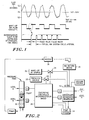
- The system just described meets several of the stated objectives, but not all. In addition, it will suffer from the system response to noise. In implementing the control function, it is necessary to account for system noise. The noisy signal, such as shown in Figure 4, creates serious problems when presented to a differentiator output. It is necessary therefore to provide a system which is somewhat more sophisticated and which can minimize or control the effects of noise. Figure 5 illustrates a preferred embodiment of the control system of the present invention. It is generally the same as the embodiment illustrated in Figure 3 but contains several additional functions which are intended to reduce the noise problems.
- To deal with noise, but to keep added time lag from being excessive, two clipper stages (42 and 54) and two filter stages (50 and 56) are incorporated in the block diagram of Figure 5. Their function will be explained hereafter. To deal with system variation over a wide range of ink types, the action of the integral term has been changed to perform error summing on a conditional basis.
- The clipper circuits allow signals to pass without time lag or phase shift as long as the magnitude of the signal is within the clipping window. If the signal is either above or below the window, the output is limited to the window maximum or minimum. Once each cycle, by virtue of the feedback path shown, the reference for the clipper window is adjusted in the direction that the signal is moving. This action greatly reduces the noise. level of the system.
- The
filters second filter 56 adds further smoothing to the resultant valve on-time pulse train. The result of these modifications is an improved flow time wave form. - Referring more specifically to Figure 5, the set point value (flow time) is provided as an input to the summing
point 40, where a comparison is made against the actual flow time obtained from the magnetic switches A and B associated with the pressure tube 10 (Figure 2). The result of the comparison is the error signal, which after clipping, is processed by the PID section of the controller. As indicated, theclipper 42 limits the error signal to a value within its current window. The window will shift up or down in the direction of the error by virtue offeedback path 44. The output of theclipper 42 is the input to all three sections of the PID control system. The proportional control simply scales the error signal by the value K1 and provides it to the summingpoint 46. The derivative section computes the derivative of the error signal at 48 and passes the resulting value through a twocycle filter 50 to reduce noise and then scales it by a constant K2. The summation function is conditionally performed, as indicated at 52, as explained hereafter. - The three components of the error signal are summed at summing
point 46, subjected to aclipper circuit 54 and afilter 56. The resultant signal is the valve on-time signal which is used to control operation of the make-upink adder valve 20. From the foregoing, it will be apparent, subject to the effects of the derivative and conditional summing terms, that the greater the error (positive), the greater the valve on-time and vice versa. Thus, unlike the fixed on-time capability of the prior art, the present invention modulates the make-up valve on-time as a function of the detected error signal. The result is far better control of ink flow time with the beneficial consequences described herein. - The overall gain of the forward transfer function, as well as the feedback transfer function, are both products of several factors. The variations of these factors result in a wide range of gain from machine to machine and from ink to ink. Such factors include:
- Viscosity of fresh ink versus make-up ink
- Evaporation rate of the ink
- Specific gravity of fresh ink versus make-up ink
- Viscosity of make-up ink
- Reservoir vacuum level
- Various restrictions to fluid flow in the make-up add system
- The solution is to allow error summing to be turned off or on in a manner that is essentially self-adjusting. When the slope of the error curve is near zero, the flow rate of make-up ink is close to the actual evaporation rate. This is true even though the error may be at a peak. Therefore, according to the present invention summing for positive errors is stopped when the slope of the error (dE/dt) decreases to -.02. Similarly, for negative errors, when the slope becomes greater than +.02, summing is stopped.
- The result of this process is that the error curve reaches its peak and continues back toward zero error just slightly. At this point, the make-up add rate just slightly exceeds the evaporation rate. Summing remains inhibited unless the slope condition changes again to re-enable it. Figure 7 shows the comparison with and without conditional summing. The net result is that over a wide range of evaporation rates and gain parameter variations, the recovery back to zero error is well controlled with little or no overshoot.
- In one embodiment, the finalized control equation was:

Where required, it is possible to further modify the control system block to include summing the derivative of the error signal multiplied by an appropriate coefficient as well as the error signal itself. For example, substituting the following term into the control function:
The idea is to more rapidly grow the sum if the error is rapidly increasing and less rapidly if not. The net effect of this feature is to rapidly limit the error peak and return the error to zero without overshoot for a wider range of gain. In high noise systems however this alteration to the basic system disclosed in Figure 5 is not desirable. High noise systems can reintroduce overshoot and oscillation. As a rule of thumb, if the noise levels are assumed to be less than 1/4 second peak-to-peak, this additional modification will work well. Where spurious noise reaches one to two seconds peak-to-peak, conditional summing of the derivative term should not be utilized. - In sum, the present invention is a means of controlling flow rate in a recirculating ink system. Control of flow rate translates directly into control of ink drop velocity, a necessary requirement for quality ink jet printing. From the foregoing, the manner of implementing this system in either solid state logic or by computer will be apparent. For completeness, however, software flow diagrams are provided by which the invention may be implemented by computer.
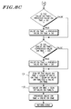
- The software shown in Figures 8a to 8d is generally self-explanatory to those skilled in the art. However, a brief review is provided to insure accuracy and completeness of the disclosure.
- Referring to Figure 8a, the software initially checks to see if the operator has manually changed the data used for operating the make-up ink valve. If so, the program branches to Figure 8d. If not, the program reads flow time and reference time and computes the error (the difference between flow time and reference time). As shown in Figure 5, the error is then passed through a clipper which limits the error to its previous value plus or minus 0.3 seconds. The derivative of the error is then taken.
- Referring to Figure 8b, the function of the two
cycle filter 50 is next implemented as shown in the final box on Figure 8a and the first three boxes on Figure 8b. After determining whether the error is positive or negative, the conditional summing function shown atbox 52 in Figure 5 is implemented. The conditional aspect of the summing is achieved by requiring that the derivative of the error be greater than -0.02 or less than +0.02. If this condition is not met, the summation used is the previous value rather than a newly computed value. - Referring to Figure 8c, the first four functions correspond to
clipper 54 in Figure 5. Boxes marked 72 and 74 in Figure 8c correspond to the two-cycle filter 56 in Figure 5. Finally, the valve on-time is stored for the next iteration of the software operation. - Referring to Figure 8d, in the event that the operator has changed the value for the make-up ink operation, the error values used for the calculation are set to zero. The previous valve on-time is set equal to the new operator enterd value. The sum of valve on-time is set to twice the new value. The previous summation is set to 64 times the new value. This is so that when the valve on-time is next calculated, the result will be the new requested value. Operation then commences as shown in Figure 8a and the PID control functions correct any error in the initial value thus selected.
Claims (14)
- An ink jet system, having an ink valve (24) by which make-up ink (20) may be added to the system to maintain flow rate substantially at a reference value as ink is lost from the system by evaporation, including means (40) for periodically comparing the reference flow-rate value with the actual flow-rate value to generate an error signal, and means for operating on the error signal to provide a signal for controlling the make-up valve (24), characterised in that the operating means includes means (K₁, 52, 48) for producing proportional (P), integral (I) and derivative (D) values derived from the error signal, means (46) for combining the proportional (P), integral (I) and derivative (D) values to produce the signal for controlling the make-up valve, and means (52) for inhibiting change of the integral value (I) so as to reduce undershoot and overshoot of the actual flow-rate value relative to the reference flow-rate value.
- An ink jet system, as claimed in Claim 1, wherein the means (46) for combining the proportional (P), integral (I) and derivative (D) values employs the relationship:

T = time during which the valve is turned on,
E = actual flow time minus reference flow time, and
K₁, K₂, K₃ are empirically determined constants. - An ink jet system, as claimed in either one of the preceding claims, wherein the inhibiting means (52) inhibits change of the integral term (I) whenever:(a) the error signal is positive and the rate of change of the error signal (dE/dt) drops algebraically below approximately -0.02; and(b) the error signal is negative and the rate of change of the error signal (dE/dt) rises algebraically above approximately +0.02.
- An ink jet system, as claimed in Claim 3, wherein the means for producing proportional (P), integral (I) and derivative (D) values produces an integral value by summing the error signal and its derivative.
- An ink jet system, as claimed in any one of the preceding claims, including clipper means (42, 54) for limiting the magnitude of the error signal and make-up valve control signal to reduce the effects of electrical noise inherent in ink jet systems.
- An ink jet system, as claimed in Claim 5, wherein the clipper means (42, 54) include feedback means (44) for periodically adjusting the limits of the clipper means to follow the error signal and make-up valve control signal.
- An ink jet system, as claimed in any one of the preceding claims, including first and second noise filter means (50, 56), the first filter means (50) being for filtering the derivative value (D) from the operating means, the second filter means (56) being for filtering the output from the combining means (46).
- An ink jet system, as claimed in Claim 7, wherein the first and second filter means (50, 56) are two-cycle filters.
- A method of controlling the operation of an ink valve (24) in an ink jet system so as to maintain the flow-rate of ink (20) substantially at a reference flow-rate value as ink is lost from the system by evaporation, comprising periodically comparing (40) the reference flow-rate value with the actual flow-rate value to generate an error signal, and operating on the error signal to provide a signal for controlling the make-up valve, characterised by producing (K₁, 52, 48) proportional (P), integral (I) and derivative (D) values derived from the error signal, combining (46) the proportional (P), integral (I) and derivative (D) values to produce the signal for controlling the make-up valve, and inhibiting (52) change of the integral value (I) so as to reduce undershoot and overshoot of the actual flow-rate value relative to the reference flow-rate value.
- A method of controlling the operation of an ink valve (24), as claimed in Claim 9, including inhibiting (52) the integral value (I) whenever:(a) the error signal is positive and the rate of change of the error signal (dE/dt) drops algebraically below approximately -0.02, and(b) the error signal is negative and the rate of change of the error signal (dE/dt) rises algebraically above approximately +0.02.
- A method of controlling the operation of an ink valve (24), as claimed in Claim 9 or Claim 10, in which the step of producing proportional (P), integral (I) and derivative (D) values produces the integral value (I) by summing the error signal and its derivative.
- A method of controlling the operation of an ink valve (24), as claimed in any one of Claims 9 to 11, including limiting (42, 54) the magnitude of the error signal and make-up control signal in clipper means to reduce the effects of electrical noise inherent in ink jet systems.
- A method of controlling the operation of an ink valve (24), as claimed in Claim 12, including periodically adjusting (44) the limits of the clipper means to follow the error signal and make-up valve control signal.
- A method of controlling the operation of an ink valve (24), as claimed in any one of Claims 9 to 13, including filtering (50) the derivative value (D) derived from the error signal, and filtering (56) the combined proportional (P), integral (I) and derivative (D) values derived from the error signal.
Applications Claiming Priority (2)
| Application Number | Priority Date | Filing Date | Title |
|---|---|---|---|
| US07/230,750 US4827280A (en) | 1988-08-09 | 1988-08-09 | Flow rate control system |
| US230750 | 1988-08-09 |
Publications (3)
| Publication Number | Publication Date |
|---|---|
| EP0354715A2 EP0354715A2 (en) | 1990-02-14 |
| EP0354715A3 EP0354715A3 (en) | 1990-08-08 |
| EP0354715B1 true EP0354715B1 (en) | 1995-06-07 |
Family
ID=22866413
Family Applications (1)
| Application Number | Title | Priority Date | Filing Date |
|---|---|---|---|
| EP89307839A Expired - Lifetime EP0354715B1 (en) | 1988-08-09 | 1989-08-02 | Flow rate control system |
Country Status (7)
| Country | Link |
|---|---|
| US (1) | US4827280A (en) |
| EP (1) | EP0354715B1 (en) |
| JP (1) | JP2598134B2 (en) |
| AT (1) | ATE123446T1 (en) |
| CA (1) | CA1322890C (en) |
| DE (1) | DE68922940T2 (en) |
| ES (1) | ES2072905T3 (en) |
Families Citing this family (22)
| Publication number | Priority date | Publication date | Assignee | Title |
|---|---|---|---|---|
| US4999645A (en) * | 1990-01-29 | 1991-03-12 | Dell Marking Systems, Inc. | Electronically controlled marking |
| GB9009957D0 (en) * | 1990-05-03 | 1990-06-27 | Domino Printing Sciences Plc | Ink supply system for continuous ink jet printer |
| CA2049454C (en) * | 1990-10-18 | 1999-01-05 | Michael E. Stamer | Automatic character height control for ink jet printers |
| US5418557A (en) * | 1991-10-03 | 1995-05-23 | Videojet Systems International, Inc. | Drop quality control system for jet printing |
| JPH0824913B2 (en) * | 1992-02-27 | 1996-03-13 | 株式会社荏原製作所 | Method and apparatus for reduction treatment of wastewater containing oxidant |
| US5517216A (en) * | 1992-07-28 | 1996-05-14 | Videojet Systems International, Inc. | Ink jet printer employing time of flight control system for ink jet printers |
| FR2695704B1 (en) * | 1992-09-15 | 1994-10-14 | Imaje | Pneumatic pressure regulator with electronic control and method for regulating the pressure of a fluid using such a regulator. |
| AT401692B (en) * | 1993-02-02 | 1996-11-25 | Vaillant Gmbh | METHOD FOR CONTROLLING A CONSUMER |
| US5424766A (en) * | 1993-11-08 | 1995-06-13 | Videojet Systems International, Inc. | Ink jet printer control system responsive to acoustical properties of ink |
| US5623292A (en) * | 1993-12-17 | 1997-04-22 | Videojet Systems International, Inc. | Temperature controller for ink jet printing |
| US5583544A (en) * | 1994-10-06 | 1996-12-10 | Videojet Systems International, Inc. | Liquid level sensor for ink jet printers |
| JP3750138B2 (en) | 1996-02-21 | 2006-03-01 | セイコーエプソン株式会社 | Ink cartridge |
| GB9603813D0 (en) * | 1996-02-22 | 1996-04-24 | Videojet Systems Int | An ink jet printing system |
| US6172694B1 (en) * | 1997-02-13 | 2001-01-09 | Marconi Data Systems Inc. | Check valve for ink jet printing |
| US6435637B1 (en) * | 1999-10-29 | 2002-08-20 | Scitex Digital Printing, Inc. | Fluid and vacuum control in an ink jet printing system |
| DE10056246B4 (en) * | 1999-12-07 | 2010-03-11 | Heidelberger Druckmaschinen Ag | Method for controlling the amount of ink in a printing machine |
| US6717537B1 (en) | 2001-06-26 | 2004-04-06 | Sonic Innovations, Inc. | Method and apparatus for minimizing latency in digital signal processing systems |
| US6615004B1 (en) | 2002-05-06 | 2003-09-02 | Hewlett-Packard Development Company, L.P. | Supplying marking fluid in an imaging system |
| US7207652B2 (en) * | 2003-10-17 | 2007-04-24 | Lexmark International, Inc. | Balanced satellite distributions |
| US11724510B2 (en) | 2018-12-12 | 2023-08-15 | Hewlett-Packard Development Company, L.P. | Interfaces to connect external print fluid supplies with print fluid reservoirs |
| CN111746124A (en) * | 2020-06-10 | 2020-10-09 | 深圳圣德京粤科技有限公司 | Circulating ink supply system |
| WO2022019883A1 (en) | 2020-07-20 | 2022-01-27 | Hewlett-Packard Development Company, L.P. | Fluid delivery system with pump servicing features |
Family Cites Families (4)
| Publication number | Priority date | Publication date | Assignee | Title |
|---|---|---|---|---|
| JPS5981177A (en) * | 1982-06-17 | 1984-05-10 | Ricoh Co Ltd | Ink viscosity controller in ink jet printer |
| GB8310711D0 (en) * | 1983-04-20 | 1983-05-25 | Cutatlas Ltd | Droplet depositing apparatus |
| US4555712A (en) * | 1984-08-03 | 1985-11-26 | Videojet Systems International, Inc. | Ink drop velocity control system |
| GB8530885D0 (en) * | 1985-12-16 | 1986-01-29 | Domino Printing Sciences Plc | Ink jet printing system |
-
1988
- 1988-08-09 US US07/230,750 patent/US4827280A/en not_active Expired - Lifetime
-
1989
- 1989-08-02 DE DE68922940T patent/DE68922940T2/en not_active Expired - Fee Related
- 1989-08-02 AT AT89307839T patent/ATE123446T1/en not_active IP Right Cessation
- 1989-08-02 EP EP89307839A patent/EP0354715B1/en not_active Expired - Lifetime
- 1989-08-02 ES ES89307839T patent/ES2072905T3/en not_active Expired - Lifetime
- 1989-08-04 JP JP1202683A patent/JP2598134B2/en not_active Expired - Fee Related
- 1989-08-04 CA CA000607603A patent/CA1322890C/en not_active Expired - Fee Related
Also Published As
| Publication number | Publication date |
|---|---|
| US4827280A (en) | 1989-05-02 |
| JP2598134B2 (en) | 1997-04-09 |
| EP0354715A2 (en) | 1990-02-14 |
| CA1322890C (en) | 1993-10-12 |
| DE68922940T2 (en) | 1995-10-19 |
| EP0354715A3 (en) | 1990-08-08 |
| ATE123446T1 (en) | 1995-06-15 |
| ES2072905T3 (en) | 1995-08-01 |
| DE68922940D1 (en) | 1995-07-13 |
| JPH02196664A (en) | 1990-08-03 |
Similar Documents
| Publication | Publication Date | Title |
|---|---|---|
| US4827280A (en) | Flow rate control system | |
| EP0845118B1 (en) | Field based process control system with auto-tuning | |
| Clarke | PID algorithms and their computer implementation | |
| US4768143A (en) | Apparatus and method using adaptive gain scheduling algorithm | |
| US4864490A (en) | Auto-tuning controller using fuzzy reasoning to obtain optimum control parameters | |
| CA2086181C (en) | Feedwater control for drum type steam generators | |
| EP0422025B1 (en) | Method and device for regulating the spraying of coating materials | |
| EP0852030B1 (en) | Adaptive bias controller | |
| EP1095778B1 (en) | Improved fluid and vacuum control in an ink jet printing system | |
| JPH04259004A (en) | Method for feedback control and tuning apparatus | |
| US6825631B1 (en) | Prediction controlling device | |
| US5268625A (en) | Adaptive control servosystems | |
| US5472312A (en) | Water level regulating system | |
| US5410470A (en) | Process control method and system with employment of fuzzy inference | |
| WO1991010177A1 (en) | Method and device for the consideration of varying volume and flow in the control of a continuous flow process | |
| US6055459A (en) | Method for preventing windup in PID controllers employing nonlinear gain | |
| US4975628A (en) | Closed-loop PWM current control for a vehicle transmission force motor | |
| US5638789A (en) | Methods and systems for controlling the amount of fuel injected in a fuel injection system | |
| EP0722134A1 (en) | Method and valve assembly for controlling a pilot signal | |
| EP0589629A1 (en) | Control of two stage valves | |
| RU2103715C1 (en) | Method for generation of regulation function | |
| CN110735721B (en) | Closed-loop control method for fuel flow of oil way of air hopper of liquid ramjet | |
| Whiteley | Fundamental principles of automatic regulators and servo mechanisms | |
| JP3124872B2 (en) | Control equipment for thermal power plant | |
| US5936368A (en) | Non-linear proportional/integral feedback controller |
Legal Events
| Date | Code | Title | Description |
|---|---|---|---|
| PUAI | Public reference made under article 153(3) epc to a published international application that has entered the european phase |
Free format text: ORIGINAL CODE: 0009012 |
|
| AK | Designated contracting states |
Kind code of ref document: A2 Designated state(s): AT BE CH DE ES FR GB GR IT LI LU NL SE |
|
| PUAL | Search report despatched |
Free format text: ORIGINAL CODE: 0009013 |
|
| AK | Designated contracting states |
Kind code of ref document: A3 Designated state(s): AT BE CH DE ES FR GB GR IT LI LU NL SE |
|
| 17P | Request for examination filed |
Effective date: 19910117 |
|
| 17Q | First examination report despatched |
Effective date: 19920922 |
|
| RAP1 | Party data changed (applicant data changed or rights of an application transferred) |
Owner name: VIDEOJET SYSTEMS INTERNATIONAL, INC. |
|
| GRAA | (expected) grant |
Free format text: ORIGINAL CODE: 0009210 |
|
| AK | Designated contracting states |
Kind code of ref document: B1 Designated state(s): AT BE CH DE ES FR GB GR IT LI LU NL SE |
|
| PG25 | Lapsed in a contracting state [announced via postgrant information from national office to epo] |
Ref country code: AT Effective date: 19950607 Ref country code: GR Free format text: LAPSE BECAUSE OF FAILURE TO SUBMIT A TRANSLATION OF THE DESCRIPTION OR TO PAY THE FEE WITHIN THE PRESCRIBED TIME-LIMIT Effective date: 19950607 |
|
| REF | Corresponds to: |
Ref document number: 123446 Country of ref document: AT Date of ref document: 19950615 Kind code of ref document: T |
|
| ITF | It: translation for a ep patent filed | ||
| REF | Corresponds to: |
Ref document number: 68922940 Country of ref document: DE Date of ref document: 19950713 |
|
| REG | Reference to a national code |
Ref country code: ES Ref legal event code: FG2A Ref document number: 2072905 Country of ref document: ES Kind code of ref document: T3 |
|
| PG25 | Lapsed in a contracting state [announced via postgrant information from national office to epo] |
Ref country code: LU Free format text: LAPSE BECAUSE OF NON-PAYMENT OF DUE FEES Effective date: 19950831 |
|
| PG25 | Lapsed in a contracting state [announced via postgrant information from national office to epo] |
Ref country code: SE Effective date: 19950907 |
|
| ET | Fr: translation filed | ||
| PLBE | No opposition filed within time limit |
Free format text: ORIGINAL CODE: 0009261 |
|
| STAA | Information on the status of an ep patent application or granted ep patent |
Free format text: STATUS: NO OPPOSITION FILED WITHIN TIME LIMIT |
|
| 26N | No opposition filed | ||
| PGFP | Annual fee paid to national office [announced via postgrant information from national office to epo] |
Ref country code: CH Payment date: 20010730 Year of fee payment: 13 |
|
| PGFP | Annual fee paid to national office [announced via postgrant information from national office to epo] |
Ref country code: NL Payment date: 20010830 Year of fee payment: 13 |
|
| REG | Reference to a national code |
Ref country code: GB Ref legal event code: IF02 |
|
| PGFP | Annual fee paid to national office [announced via postgrant information from national office to epo] |
Ref country code: ES Payment date: 20020826 Year of fee payment: 14 |
|
| PG25 | Lapsed in a contracting state [announced via postgrant information from national office to epo] |
Ref country code: LI Free format text: LAPSE BECAUSE OF NON-PAYMENT OF DUE FEES Effective date: 20020831 Ref country code: CH Free format text: LAPSE BECAUSE OF NON-PAYMENT OF DUE FEES Effective date: 20020831 |
|
| PGFP | Annual fee paid to national office [announced via postgrant information from national office to epo] |
Ref country code: BE Payment date: 20021017 Year of fee payment: 14 |
|
| PG25 | Lapsed in a contracting state [announced via postgrant information from national office to epo] |
Ref country code: NL Free format text: LAPSE BECAUSE OF NON-PAYMENT OF DUE FEES Effective date: 20030301 |
|
| REG | Reference to a national code |
Ref country code: CH Ref legal event code: PL |
|
| NLV4 | Nl: lapsed or anulled due to non-payment of the annual fee |
Effective date: 20030301 |
|
| PG25 | Lapsed in a contracting state [announced via postgrant information from national office to epo] |
Ref country code: ES Free format text: LAPSE BECAUSE OF NON-PAYMENT OF DUE FEES Effective date: 20030804 |
|
| PG25 | Lapsed in a contracting state [announced via postgrant information from national office to epo] |
Ref country code: BE Free format text: LAPSE BECAUSE OF NON-PAYMENT OF DUE FEES Effective date: 20030831 |
|
| BERE | Be: lapsed |
Owner name: *VIDEOJET SYSTEMS INTERNATIONAL INC. Effective date: 20030831 |
|
| REG | Reference to a national code |
Ref country code: ES Ref legal event code: FD2A Effective date: 20030804 |
|
| PG25 | Lapsed in a contracting state [announced via postgrant information from national office to epo] |
Ref country code: IT Free format text: LAPSE BECAUSE OF NON-PAYMENT OF DUE FEES;WARNING: LAPSES OF ITALIAN PATENTS WITH EFFECTIVE DATE BEFORE 2007 MAY HAVE OCCURRED AT ANY TIME BEFORE 2007. THE CORRECT EFFECTIVE DATE MAY BE DIFFERENT FROM THE ONE RECORDED. Effective date: 20050802 |
|
| PGFP | Annual fee paid to national office [announced via postgrant information from national office to epo] |
Ref country code: DE Payment date: 20060727 Year of fee payment: 18 |
|
| PGFP | Annual fee paid to national office [announced via postgrant information from national office to epo] |
Ref country code: GB Payment date: 20070801 Year of fee payment: 19 |
|
| PGFP | Annual fee paid to national office [announced via postgrant information from national office to epo] |
Ref country code: FR Payment date: 20070808 Year of fee payment: 19 |
|
| PG25 | Lapsed in a contracting state [announced via postgrant information from national office to epo] |
Ref country code: DE Free format text: LAPSE BECAUSE OF NON-PAYMENT OF DUE FEES Effective date: 20080301 |
|
| GBPC | Gb: european patent ceased through non-payment of renewal fee |
Effective date: 20080802 |
|
| REG | Reference to a national code |
Ref country code: FR Ref legal event code: ST Effective date: 20090430 |
|
| PG25 | Lapsed in a contracting state [announced via postgrant information from national office to epo] |
Ref country code: FR Free format text: LAPSE BECAUSE OF NON-PAYMENT OF DUE FEES Effective date: 20080901 |
|
| PG25 | Lapsed in a contracting state [announced via postgrant information from national office to epo] |
Ref country code: GB Free format text: LAPSE BECAUSE OF NON-PAYMENT OF DUE FEES Effective date: 20080802 |