EP0354642B1 - An armature drive shaft assembly - Google Patents
An armature drive shaft assembly Download PDFInfo
- Publication number
- EP0354642B1 EP0354642B1 EP19890305004 EP89305004A EP0354642B1 EP 0354642 B1 EP0354642 B1 EP 0354642B1 EP 19890305004 EP19890305004 EP 19890305004 EP 89305004 A EP89305004 A EP 89305004A EP 0354642 B1 EP0354642 B1 EP 0354642B1
- Authority
- EP
- European Patent Office
- Prior art keywords
- drive shaft
- armature
- commutator
- shaft assembly
- resistive coating
- Prior art date
- Legal status (The legal status is an assumption and is not a legal conclusion. Google has not performed a legal analysis and makes no representation as to the accuracy of the status listed.)
- Expired - Lifetime
Links
- 238000000576 coating method Methods 0.000 claims description 24
- 239000011248 coating agent Substances 0.000 claims description 23
- 238000004804 winding Methods 0.000 claims description 18
- 238000005507 spraying Methods 0.000 claims description 3
- 230000001419 dependent effect Effects 0.000 description 3
- 230000000694 effects Effects 0.000 description 2
- 230000003628 erosive effect Effects 0.000 description 2
- 230000001629 suppression Effects 0.000 description 2
- 230000001052 transient effect Effects 0.000 description 2
- OKTJSMMVPCPJKN-UHFFFAOYSA-N Carbon Chemical compound [C] OKTJSMMVPCPJKN-UHFFFAOYSA-N 0.000 description 1
- 238000001816 cooling Methods 0.000 description 1
- 229910002804 graphite Inorganic materials 0.000 description 1
- 239000010439 graphite Substances 0.000 description 1
- 239000000463 material Substances 0.000 description 1
- 238000000034 method Methods 0.000 description 1
Images

Classifications
-
- H—ELECTRICITY
- H02—GENERATION; CONVERSION OR DISTRIBUTION OF ELECTRIC POWER
- H02K—DYNAMO-ELECTRIC MACHINES
- H02K11/00—Structural association of dynamo-electric machines with electric components or with devices for shielding, monitoring or protection
- H02K11/02—Structural association of dynamo-electric machines with electric components or with devices for shielding, monitoring or protection for suppression of electromagnetic interference
- H02K11/028—Suppressors associated with the rotor
-
- H—ELECTRICITY
- H02—GENERATION; CONVERSION OR DISTRIBUTION OF ELECTRIC POWER
- H02K—DYNAMO-ELECTRIC MACHINES
- H02K13/00—Structural associations of current collectors with motors or generators, e.g. brush mounting plates or connections to windings; Disposition of current collectors in motors or generators; Arrangements for improving commutation
- H02K13/10—Arrangements of brushes or commutators specially adapted for improving commutation
- H02K13/105—Spark suppressors associated with the commutator
Definitions
- This invention relates to an armature drive shaft assembly for an electric motor, and has particular application for an electric motor for use on a motor vehicle.
- electric motors are usually permanent magnet motors and include those used for the windscreen wipers, radiator cooling fan, air blower fan, window lift motors etc.
- radio frequency (RF) noise voltages are generated by electric motors due the action of the commutator generating sparking at the interface of the commutator and the brushes. Sparking is generated by the action of the commutator switching successive armature windings to the supply voltage to cause rotation of the armature. This make and break of the armature supply voltage generates a rapid increase and then decrease in the magnetic field associated with the armature. Each time this magnetic field collapses, a high voltage is generated in the reverse direction to the supply voltage. This causes a high, substantially instantaneous, current to flow in the supply voltage circuit, generating a spark between the commutator and the brushes.
- RF radio frequency
- This action has two effects; firstly it generates an RF current in the external supply voltage circuit, causing radio interference; and secondly it generates a high voltage transient as each commutator segment switches an armature winding from the supply voltage circuit. This problem is particularly prevalent when the electric motor is switched off, when a high back EMF or reverse voltage is generated.
- Patent applications GB-A-2 087 661, US-A-3 487 248 and DE-A-1 929 984 each discloses arrangements for reducing electrical noise and brush sparking in commutated electric motors, wherein the segments of the commutators are connected together by electrically resistive coatings.
- an armature drive shaft assembly in accordance with the present invention comprises a drive shaft; an armature comprising armature windings wound on the drive shaft; a commutator positioned on the drive shaft and comprising commutator segments which are connected to the armature windings; and a resistive coating connecting the commutator segments to provide a linear resistive path therebetween; wherein the drive shaft is connectable to electrical ground, and wherein the resistive coating connects the commutator segments to the drive shaft.
- the present invention not only reduces the RF currents, but also provides an arrangement whereby the RF currents can be contained within the casing of the electric motor, by effectively placing a linear resistive path across each armature winding, and to the casing by way of the drive shaft.
- the present invention has the additional advantage of keeping the back EMF voltages below 150 volts at switch off, which significantly reduces electrical erosion at the interface of the brushes and the commutator, thereby extending the life of the brushes and the electric motor.
- the present invention can be used on standard electric motors without the use of a special commutator.
- the resistive coating provides a linear resistive path between the commutator segments which is not voltage dependent, and which is far more efficient in reducing RF currents.
- the resistive coating coats each circumferential end of the commutator to directly connect each end of each commutator segment to the drive shaft, and to directly connect each end of each armature winding to the drive shaft.
- the resistive coating is only on one circumferential end of the commutator, and, in this case, is preferably applied prior to winding the armature.
- the resistive coating preferably provides a linear resistance between each commutator segment and the drive shaft, if required, in the range 25 to 200 ohms, although the present invention is not limited to these values.
- the resistive coating has been applied by spraying.
- the present invention also includes an electric motor having an armature drive shaft assembly as herein defined.
- armature drive shaft assembly 10 comprises a drive shaft 11, an armature 12 comprising armature windings 14, and a commutator 15 comprising commutator segments 16 connected individually to an armature winding.
- the equivalent electric circuit shown in Figure 2 includes the drive shaft 11, and a pair of commutator segments 16 connected to a pair of armature windings 14. Also shown are a pair of brushes 17 associated with the commutator, which are connected via terminals 18 to a supply voltage circuit (not shown), and a pair of permanent magnets 20. Although only one pair of commutator segments and armature windings is shown, it will be appreciated that the arrangement is the same for all of the commutator segments and armature windings.
- sparking generated between the commutator segments 16 and the brushes 17 generates RF voltages having a current path indicated by the arrows labelled RF.
- the present invention is an armature drive shaft assembly 50 comprising a drive shaft 51, an armature 52 comprising armature windings 54, and a commutator 55 comprising commutator segments 56.
- the drive shaft 51 is connected to the casing (not shown) of the electric motor, and hence to ground, by way of bearing surfaces 72 for the drive shaft.
- the resistive coating provides a resistive path R between the commutator segments 56 and the drive shaft 51.
- the RF current path is now through the drive shaft 51 and the casing to ground, and not through the supply voltage circuit.
- the use of a resistive coating 70 is obviously far more practical than discrete resistors placed within the assembly, as discrete resistors would cause problems with balancing of the assembly at high speeds.
- the advantage of the present invention is that a resistor arrangement can be provided within the assembly without affecting the balance of the assembly, and that a standard assembly can be easily modified to accommodate the present invention. This has been shown to reduce sparking at the commutator 55 by reducing the size of the RF currents generated at this source and also containing most of the RF current within the assembly itself.
- the present invention has been found to have the additional advantage of reducing the back EMF generated when the electric motor is switched off by providing a resistive path to ground for the generated currents.
- the resistive coating 70 can be applied by spraying over the commutator 55 and extending to the drive shaft 51 either before or after the armature 52 is wound. The commutator 55 is then skimmed and undercut to expose an area for contact by the brushes 57. Suitable alternative methods of applying the resistive coating could of course be used.
- Suitable materials for the resistive coating 70 include a nickle coating of approximately 0.7 ohms/sq. A graphite coating of approximately 20 ohms/sq. also gives acceptable results.
- the preferred range for linear resistance R between each commutator segment 56 and the drive shaft 51 for an electric motor for a windscreen wiper of a motor vehicle is 25 to 200 ohms. This provides a compromise between adequate suppression of the RF voltage generated noise without greatly increasing the supply current. This range may be adjusted to suit other applications of electric motors.
Landscapes
- Engineering & Computer Science (AREA)
- Power Engineering (AREA)
- Physics & Mathematics (AREA)
- Electromagnetism (AREA)
- Dc Machiner (AREA)
- Motor Or Generator Current Collectors (AREA)
Description
- This invention relates to an armature drive shaft assembly for an electric motor, and has particular application for an electric motor for use on a motor vehicle. Such electric motors are usually permanent magnet motors and include those used for the windscreen wipers, radiator cooling fan, air blower fan, window lift motors etc.
- It is well known that radio frequency (RF) noise voltages are generated by electric motors due the action of the commutator generating sparking at the interface of the commutator and the brushes. Sparking is generated by the action of the commutator switching successive armature windings to the supply voltage to cause rotation of the armature. This make and break of the armature supply voltage generates a rapid increase and then decrease in the magnetic field associated with the armature. Each time this magnetic field collapses, a high voltage is generated in the reverse direction to the supply voltage. This causes a high, substantially instantaneous, current to flow in the supply voltage circuit, generating a spark between the commutator and the brushes. This action has two effects; firstly it generates an RF current in the external supply voltage circuit, causing radio interference; and secondly it generates a high voltage transient as each commutator segment switches an armature winding from the supply voltage circuit. This problem is particularly prevalent when the electric motor is switched off, when a high back EMF or reverse voltage is generated.
- Previously known arrangements for suppressing or reducing these RF currents rely on the use of components being placed across the brushes external to the armature drive shaft assembly. These known arrangements have been expensive, and are not always effective.
- It is an object of this invention to substantially reduce the above mentioned two effects, and the disadvantages associated therewith, in a cost effective way.
- Patent applications GB-A-2 087 661, US-A-3 487 248 and DE-A-1 929 984 each discloses arrangements for reducing electrical noise and brush sparking in commutated electric motors, wherein the segments of the commutators are connected together by electrically resistive coatings.
- It is known from GB Patent No. 1337343 to provide a commutator having voltage dependent resistor characteristics. This requires the use of a special commutator, and hence changes to the basic design. Further, the use of voltage dependent resistance characteristics does not efficiently suppress or reduce RF currents.
- It is a further object of the present invention to overcome the above disadvantages.
- To this end, an armature drive shaft assembly in accordance with the present invention comprises a drive shaft; an armature comprising armature windings wound on the drive shaft; a commutator positioned on the drive shaft and comprising commutator segments which are connected to the armature windings; and a resistive coating connecting the commutator segments to provide a linear resistive path therebetween; wherein the drive shaft is connectable to electrical ground, and wherein the resistive coating connects the commutator segments to the drive shaft.
- It has been shown by tests that a simple and effective way of reducing the currents generated by the RF voltages is to provide an alternative path for these RF currents within the casing of the electric motor, thereby containing the RF currents within the casing. The present invention not only reduces the RF currents, but also provides an arrangement whereby the RF currents can be contained within the casing of the electric motor, by effectively placing a linear resistive path across each armature winding, and to the casing by way of the drive shaft. The present invention has the additional advantage of keeping the back EMF voltages below 150 volts at switch off, which significantly reduces electrical erosion at the interface of the brushes and the commutator, thereby extending the life of the brushes and the electric motor. Further still, the present invention can be used on standard electric motors without the use of a special commutator. The resistive coating provides a linear resistive path between the commutator segments which is not voltage dependent, and which is far more efficient in reducing RF currents.
- Preferably, the resistive coating coats each circumferential end of the commutator to directly connect each end of each commutator segment to the drive shaft, and to directly connect each end of each armature winding to the drive shaft. Alternatively, the resistive coating is only on one circumferential end of the commutator, and, in this case, is preferably applied prior to winding the armature.
- The resistive coating preferably provides a linear resistance between each commutator segment and the drive shaft, if required, in the range 25 to 200 ohms, although the present invention is not limited to these values.
- Preferably, the resistive coating has been applied by spraying.
- The present invention also includes an electric motor having an armature drive shaft assembly as herein defined.
- The present invention will now be described, by way of example, with reference to the accompanying drawings, in which:-
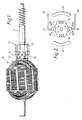
- Figure 1 is a side view of a known armature drive shaft assembly;
- Figure 2 is a diagrammatic representation of the electric circuit of the armature drive shaft assembly shown in Figure 1;
- Figure 3 is a side view of an armature drive shaft assembly in accordance with the present invention; and
- Figure 4 is a diagrammatic representation of the electric circuit of the armature drive shaft assembly shown in Figure 3.
- Referring to Figure 1, the known prior art arrangement of armature
drive shaft assembly 10 comprises adrive shaft 11, anarmature 12 comprisingarmature windings 14, and acommutator 15 comprisingcommutator segments 16 connected individually to an armature winding. - The equivalent electric circuit shown in Figure 2 includes the
drive shaft 11, and a pair ofcommutator segments 16 connected to a pair ofarmature windings 14. Also shown are a pair ofbrushes 17 associated with the commutator, which are connected viaterminals 18 to a supply voltage circuit (not shown), and a pair ofpermanent magnets 20. Although only one pair of commutator segments and armature windings is shown, it will be appreciated that the arrangement is the same for all of the commutator segments and armature windings. - In this known arrangement, sparking generated between the
commutator segments 16 and thebrushes 17 generates RF voltages having a current path indicated by the arrows labelled RF. - The present invention, as indicated by the embodiment shown in Figure 3, is an armature
drive shaft assembly 50 comprising adrive shaft 51, anarmature 52 comprisingarmature windings 54, and acommutator 55 comprisingcommutator segments 56. A linear resistive path between thearmature windings 54, and between thecommutator segments 56 and thedrive shaft 51, is provided by aresistive coating 70. Thedrive shaft 51 is connected to the casing (not shown) of the electric motor, and hence to ground, by way of bearingsurfaces 72 for the drive shaft. - As can be seen from the equivalent electric circuit shown in Figure 4, which also shows a pair of
brushes 57,terminals 58 to a supply voltage circuit (not shown), andpermanent magnets 60, the resistive coating provides a resistive path R between thecommutator segments 56 and thedrive shaft 51. As a consequence, the RF current path is now through thedrive shaft 51 and the casing to ground, and not through the supply voltage circuit. - The use of a
resistive coating 70 is obviously far more practical than discrete resistors placed within the assembly, as discrete resistors would cause problems with balancing of the assembly at high speeds. The advantage of the present invention is that a resistor arrangement can be provided within the assembly without affecting the balance of the assembly, and that a standard assembly can be easily modified to accommodate the present invention. This has been shown to reduce sparking at thecommutator 55 by reducing the size of the RF currents generated at this source and also containing most of the RF current within the assembly itself. The present invention has been found to have the additional advantage of reducing the back EMF generated when the electric motor is switched off by providing a resistive path to ground for the generated currents. - The
resistive coating 70 can be applied by spraying over thecommutator 55 and extending to thedrive shaft 51 either before or after thearmature 52 is wound. Thecommutator 55 is then skimmed and undercut to expose an area for contact by thebrushes 57. Suitable alternative methods of applying the resistive coating could of course be used. - Suitable materials for the
resistive coating 70 include a nickle coating of approximately 0.7 ohms/sq. A graphite coating of approximately 20 ohms/sq. also gives acceptable results. - The preferred range for linear resistance R between each
commutator segment 56 and thedrive shaft 51 for an electric motor for a windscreen wiper of a motor vehicle is 25 to 200 ohms. This provides a compromise between adequate suppression of the RF voltage generated noise without greatly increasing the supply current. This range may be adjusted to suit other applications of electric motors. - An improvement in suppression of 10 dB has been found to be typical with a resistive coating having a resistance of 25 ohms. Further, the switch-off transient was found to be reduced below 150 volts, thereby reducing the electrical erosion at the commutator/brush interface, with a consequent increase in brush and motor life.
Claims (6)
- An armature drive shaft assembly (50) for an electric motor comprising a drive shaft (51); an armature (52) comprising armature windings (54) wound on the drive shaft; a commutator (55) positioned on the drive shaft and comprising commutator segments (56) which are connected to the armature windings; a resistive coating (70) connecting the commutator segments (56) to provide a linear resistive path (R) therebetween; characterised in that the drive shaft (51) is connectable (72) to electrical ground, and in that the resistive coating (70) connects the commutator segments (56) to the drive shaft.
- An armature drive shaft assembly as claimed in claim 1, wherein the resistive coating (70) coats each circumferential end of the commutator (55) to directly connect each end of each commutator segment (56) to the drive shaft (51), and to directly connect each end of each armature winding (54) to the drive shaft.
- An armature drive shaft assembly as claimed in claim 1, wherein the resistive coating (70) is only on one circumferential end of the commutator (55), and wherein the resistive coating has been applied prior to winding the armature (52).
- An armature drive shaft assembly as claimed in any one of claims 1 to 3, wherein the resistive coating (70) provides a linear resistance (R) between each commutator segment (56) and the drive shaft (51) in the range 25 to 200 ohms.
- An armature drive shaft assembly as claimed in any one of claims 1 to 4, wherein the resistive coating (70) has been applied by spraying.
- An electric motor comprising an armature drive shaft assembly as claimed in any one of the preceding claims.
Applications Claiming Priority (2)
| Application Number | Priority Date | Filing Date | Title |
|---|---|---|---|
| GB888818721A GB8818721D0 (en) | 1988-08-06 | 1988-08-06 | Armature drive shaft assembly |
| GB8818721 | 1988-08-06 |
Publications (3)
| Publication Number | Publication Date |
|---|---|
| EP0354642A2 EP0354642A2 (en) | 1990-02-14 |
| EP0354642A3 EP0354642A3 (en) | 1990-12-05 |
| EP0354642B1 true EP0354642B1 (en) | 1993-11-03 |
Family
ID=10641719
Family Applications (1)
| Application Number | Title | Priority Date | Filing Date |
|---|---|---|---|
| EP19890305004 Expired - Lifetime EP0354642B1 (en) | 1988-08-06 | 1989-05-17 | An armature drive shaft assembly |
Country Status (4)
| Country | Link |
|---|---|
| EP (1) | EP0354642B1 (en) |
| DE (1) | DE68910422T2 (en) |
| ES (1) | ES2045426T3 (en) |
| GB (3) | GB8818721D0 (en) |
Families Citing this family (4)
| Publication number | Priority date | Publication date | Assignee | Title |
|---|---|---|---|---|
| JPH0564397A (en) * | 1991-08-29 | 1993-03-12 | Mitsubishi Electric Corp | Direct current motor |
| DE4233132A1 (en) * | 1992-10-02 | 1994-04-07 | Bosch Gmbh Robert | Interference suppressed electrical commutator machine |
| GB2402556A (en) * | 2003-05-28 | 2004-12-08 | Johnson Electric Sa | Commutator including moulded varistor |
| JP5877002B2 (en) * | 2011-07-25 | 2016-03-02 | 株式会社ミツバ | Assembling method of motor device |
Family Cites Families (12)
| Publication number | Priority date | Publication date | Assignee | Title |
|---|---|---|---|---|
| FR1053236A (en) * | 1952-03-31 | 1954-02-01 | Radio Electr Soc Fr | Improvements to anti-interference devices for rotating electric machines comprising a manifold |
| US3487248A (en) * | 1966-02-17 | 1969-12-30 | Victor Company Of Japan | Balanced dc motor rotor with spark reducing commutating arrangement |
| DE1929984A1 (en) * | 1968-06-14 | 1970-01-02 | Tokyo Kagaku Kabushiki Kaisha | Micromotor |
| DE2055648B2 (en) * | 1970-11-12 | 1972-09-28 | Fa. C. Conradty, 8500 Nürnberg | VOLTAGE-DEPENDENT COLLECTOR FOR SMALL OR SMALL MOTORS AND THE PROCESS FOR ITS MANUFACTURING |
| DE2242528A1 (en) * | 1971-09-01 | 1973-03-08 | Gen Electric | COMMUTATOR FOR ROTATING ELECTRIC MACHINERY |
| JPS5417008U (en) * | 1977-07-08 | 1979-02-03 | ||
| JPS622942Y2 (en) * | 1980-10-23 | 1987-01-23 | ||
| JPS622358U (en) * | 1985-06-18 | 1987-01-08 | ||
| JPS6284365U (en) * | 1985-11-15 | 1987-05-29 | ||
| JPH0448139Y2 (en) * | 1986-04-15 | 1992-11-12 | ||
| GB2203596A (en) * | 1987-03-23 | 1988-10-19 | Johnson Electric Ind Mfg | Winding connections retention in an armature for an electric motor |
| GB2202686B (en) * | 1987-03-23 | 1991-08-14 | Johnson Electric Ind Mfg | An armature for an electric motor |
-
1988
- 1988-08-06 GB GB888818721A patent/GB8818721D0/en active Pending
- 1988-10-13 GB GB8824002A patent/GB2221581A/en not_active Withdrawn
-
1989
- 1989-05-17 GB GB8911351A patent/GB2221582B/en not_active Expired - Lifetime
- 1989-05-17 DE DE1989610422 patent/DE68910422T2/en not_active Expired - Fee Related
- 1989-05-17 ES ES89305004T patent/ES2045426T3/en not_active Expired - Lifetime
- 1989-05-17 EP EP19890305004 patent/EP0354642B1/en not_active Expired - Lifetime
Also Published As
| Publication number | Publication date |
|---|---|
| GB8911351D0 (en) | 1989-07-05 |
| GB8824002D0 (en) | 1988-11-23 |
| GB8818721D0 (en) | 1988-09-07 |
| GB2221581A (en) | 1990-02-07 |
| ES2045426T3 (en) | 1994-01-16 |
| DE68910422T2 (en) | 1994-02-24 |
| EP0354642A2 (en) | 1990-02-14 |
| EP0354642A3 (en) | 1990-12-05 |
| DE68910422D1 (en) | 1993-12-09 |
| GB2221582A (en) | 1990-02-07 |
| GB2221582B (en) | 1992-10-07 |
Similar Documents
| Publication | Publication Date | Title |
|---|---|---|
| JP4919571B2 (en) | Filtering and interference suppression devices for motors | |
| EP0040484B1 (en) | Brushless d.c. motors | |
| US6285109B1 (en) | Small motor with improved connecting structure between coil, riser and varistor | |
| US4748388A (en) | Brushless d.c. motor having RC time-delay stage(s) and driver transistors which prevent simultaneous conduction by the power transistors of the wound conductor pair(s) of the motor winding | |
| US6304012B1 (en) | Alternator | |
| US4728835A (en) | Electric motors | |
| CA2190356A1 (en) | Improved multi-speed motor | |
| CA2140659A1 (en) | Permanent magnet direct current motor | |
| JPH0334302B2 (en) | ||
| CA1088141A (en) | Electrically isolated brush holder | |
| US8975796B2 (en) | Electric motor and electric equipment with same | |
| US6984906B1 (en) | Bearing current reduction assembly | |
| EP0354642A2 (en) | An armature drive shaft assembly | |
| US3487248A (en) | Balanced dc motor rotor with spark reducing commutating arrangement | |
| MXPA01008335A (en) | Electric motor. | |
| GB2183933A (en) | Electric motor having a spark-quenched commutator | |
| GB2177854A (en) | Spark suppressed commutator | |
| EP0354643A2 (en) | An armature drive shaft assembly | |
| JP2005261190A (en) | Electric motor having interference suppression device | |
| EP0277431B1 (en) | Two-speed motor | |
| JP2632908B2 (en) | DC motor | |
| CN114223116A (en) | Motor and electric apparatus | |
| GB2271220A (en) | Electrical connector with radio interference suppression. | |
| US3469166A (en) | Direct current motor speed control | |
| KR810000740Y1 (en) | DC motor |
Legal Events
| Date | Code | Title | Description |
|---|---|---|---|
| PUAI | Public reference made under article 153(3) epc to a published international application that has entered the european phase |
Free format text: ORIGINAL CODE: 0009012 |
|
| AK | Designated contracting states |
Kind code of ref document: A2 Designated state(s): DE ES FR SE |
|
| PUAL | Search report despatched |
Free format text: ORIGINAL CODE: 0009013 |
|
| AK | Designated contracting states |
Kind code of ref document: A3 Designated state(s): DE ES FR SE |
|
| 17P | Request for examination filed |
Effective date: 19910307 |
|
| RAP1 | Party data changed (applicant data changed or rights of an application transferred) |
Owner name: DELCO CHASSIS OVERSEAS CORPORATION |
|
| 17Q | First examination report despatched |
Effective date: 19930203 |
|
| GRAA | (expected) grant |
Free format text: ORIGINAL CODE: 0009210 |
|
| AK | Designated contracting states |
Kind code of ref document: B1 Designated state(s): DE ES FR SE |
|
| REF | Corresponds to: |
Ref document number: 68910422 Country of ref document: DE Date of ref document: 19931209 |
|
| ET | Fr: translation filed | ||
| REG | Reference to a national code |
Ref country code: ES Ref legal event code: FG2A Ref document number: 2045426 Country of ref document: ES Kind code of ref document: T3 |
|
| PG25 | Lapsed in a contracting state [announced via postgrant information from national office to epo] |
Ref country code: SE Effective date: 19940518 Ref country code: ES Free format text: LAPSE BECAUSE OF NON-PAYMENT OF DUE FEES Effective date: 19940518 |
|
| PGFP | Annual fee paid to national office [announced via postgrant information from national office to epo] |
Ref country code: FR Payment date: 19940530 Year of fee payment: 6 |
|
| RAP2 | Party data changed (patent owner data changed or rights of a patent transferred) |
Owner name: AUTOMOTIVE COMPONENTS DUNSTABLE LIMITED |
|
| PLBE | No opposition filed within time limit |
Free format text: ORIGINAL CODE: 0009261 |
|
| STAA | Information on the status of an ep patent application or granted ep patent |
Free format text: STATUS: NO OPPOSITION FILED WITHIN TIME LIMIT |
|
| 26N | No opposition filed | ||
| EUG | Se: european patent has lapsed |
Ref document number: 89305004.7 Effective date: 19941210 |
|
| PG25 | Lapsed in a contracting state [announced via postgrant information from national office to epo] |
Ref country code: DE Effective date: 19950201 |
|
| EUG | Se: european patent has lapsed |
Ref document number: 89305004.7 |
|
| PG25 | Lapsed in a contracting state [announced via postgrant information from national office to epo] |
Ref country code: FR Effective date: 19960229 |
|
| REG | Reference to a national code |
Ref country code: FR Ref legal event code: ST |
|
| REG | Reference to a national code |
Ref country code: FR Ref legal event code: ST |
|
| REG | Reference to a national code |
Ref country code: ES Ref legal event code: FD2A Effective date: 19990301 |