EP0353954B1 - Improvements in and relating to braking devices - Google Patents
Improvements in and relating to braking devices Download PDFInfo
- Publication number
- EP0353954B1 EP0353954B1 EP89307670A EP89307670A EP0353954B1 EP 0353954 B1 EP0353954 B1 EP 0353954B1 EP 89307670 A EP89307670 A EP 89307670A EP 89307670 A EP89307670 A EP 89307670A EP 0353954 B1 EP0353954 B1 EP 0353954B1
- Authority
- EP
- European Patent Office
- Prior art keywords
- body part
- movement
- brake lock
- movable surface
- braking device
- Prior art date
- Legal status (The legal status is an assumption and is not a legal conclusion. Google has not performed a legal analysis and makes no representation as to the accuracy of the status listed.)
- Expired - Lifetime
Links
- 230000033001 locomotion Effects 0.000 claims abstract description 65
- 230000036961 partial effect Effects 0.000 claims abstract description 11
- 230000002441 reversible effect Effects 0.000 claims description 13
- 230000002093 peripheral effect Effects 0.000 claims description 6
- 230000000694 effects Effects 0.000 claims 1
- 238000010276 construction Methods 0.000 description 11
- 230000004048 modification Effects 0.000 description 11
- 238000012986 modification Methods 0.000 description 11
- 239000000463 material Substances 0.000 description 7
- 230000007935 neutral effect Effects 0.000 description 6
- 229920003023 plastic Polymers 0.000 description 5
- 239000004033 plastic Substances 0.000 description 5
- 230000001050 lubricating effect Effects 0.000 description 4
- 230000000717 retained effect Effects 0.000 description 4
- 239000000428 dust Substances 0.000 description 3
- 238000007789 sealing Methods 0.000 description 3
- 230000000994 depressogenic effect Effects 0.000 description 2
- 230000026058 directional locomotion Effects 0.000 description 2
- 239000002184 metal Substances 0.000 description 2
- 238000007493 shaping process Methods 0.000 description 2
- 101100334009 Caenorhabditis elegans rib-2 gene Proteins 0.000 description 1
- 229910000831 Steel Inorganic materials 0.000 description 1
- 230000002411 adverse Effects 0.000 description 1
- XTKDAFGWCDAMPY-UHFFFAOYSA-N azaperone Chemical compound C1=CC(F)=CC=C1C(=O)CCCN1CCN(C=2N=CC=CC=2)CC1 XTKDAFGWCDAMPY-UHFFFAOYSA-N 0.000 description 1
- 230000000295 complement effect Effects 0.000 description 1
- 230000006835 compression Effects 0.000 description 1
- 238000007906 compression Methods 0.000 description 1
- 230000007797 corrosion Effects 0.000 description 1
- 238000005260 corrosion Methods 0.000 description 1
- 230000001419 dependent effect Effects 0.000 description 1
- 230000000670 limiting effect Effects 0.000 description 1
- 239000007769 metal material Substances 0.000 description 1
- 230000002787 reinforcement Effects 0.000 description 1
- 239000010959 steel Substances 0.000 description 1
- 210000003813 thumb Anatomy 0.000 description 1
Images




Classifications
-
- F—MECHANICAL ENGINEERING; LIGHTING; HEATING; WEAPONS; BLASTING
- F16—ENGINEERING ELEMENTS AND UNITS; GENERAL MEASURES FOR PRODUCING AND MAINTAINING EFFECTIVE FUNCTIONING OF MACHINES OR INSTALLATIONS; THERMAL INSULATION IN GENERAL
- F16D—COUPLINGS FOR TRANSMITTING ROTATION; CLUTCHES; BRAKES
- F16D65/00—Parts or details
- F16D65/14—Actuating mechanisms for brakes; Means for initiating operation at a predetermined position
-
- A—HUMAN NECESSITIES
- A61—MEDICAL OR VETERINARY SCIENCE; HYGIENE
- A61G—TRANSPORT, PERSONAL CONVEYANCES, OR ACCOMMODATION SPECIALLY ADAPTED FOR PATIENTS OR DISABLED PERSONS; OPERATING TABLES OR CHAIRS; CHAIRS FOR DENTISTRY; FUNERAL DEVICES
- A61G5/00—Chairs or personal conveyances specially adapted for patients or disabled persons, e.g. wheelchairs
- A61G5/10—Parts, details or accessories
- A61G5/1005—Wheelchairs having brakes
- A61G5/1013—Wheelchairs having brakes engaging the wheel
- A61G5/1018—Wheelchairs having brakes engaging the wheel on the running surface
-
- A—HUMAN NECESSITIES
- A61—MEDICAL OR VETERINARY SCIENCE; HYGIENE
- A61G—TRANSPORT, PERSONAL CONVEYANCES, OR ACCOMMODATION SPECIALLY ADAPTED FOR PATIENTS OR DISABLED PERSONS; OPERATING TABLES OR CHAIRS; CHAIRS FOR DENTISTRY; FUNERAL DEVICES
- A61G5/00—Chairs or personal conveyances specially adapted for patients or disabled persons, e.g. wheelchairs
- A61G5/10—Parts, details or accessories
- A61G5/1005—Wheelchairs having brakes
- A61G5/101—Wheelchairs having brakes of the parking brake type, e.g. holding the wheelchair
-
- A—HUMAN NECESSITIES
- A61—MEDICAL OR VETERINARY SCIENCE; HYGIENE
- A61G—TRANSPORT, PERSONAL CONVEYANCES, OR ACCOMMODATION SPECIALLY ADAPTED FOR PATIENTS OR DISABLED PERSONS; OPERATING TABLES OR CHAIRS; CHAIRS FOR DENTISTRY; FUNERAL DEVICES
- A61G5/00—Chairs or personal conveyances specially adapted for patients or disabled persons, e.g. wheelchairs
- A61G5/10—Parts, details or accessories
- A61G5/1005—Wheelchairs having brakes
- A61G5/1035—Wheelchairs having brakes manipulated by wheelchair user
-
- B—PERFORMING OPERATIONS; TRANSPORTING
- B60—VEHICLES IN GENERAL
- B60T—VEHICLE BRAKE CONTROL SYSTEMS OR PARTS THEREOF; BRAKE CONTROL SYSTEMS OR PARTS THEREOF, IN GENERAL; ARRANGEMENT OF BRAKING ELEMENTS ON VEHICLES IN GENERAL; PORTABLE DEVICES FOR PREVENTING UNWANTED MOVEMENT OF VEHICLES; VEHICLE MODIFICATIONS TO FACILITATE COOLING OF BRAKES
- B60T1/00—Arrangements of braking elements, i.e. of those parts where braking effect occurs specially for vehicles
- B60T1/02—Arrangements of braking elements, i.e. of those parts where braking effect occurs specially for vehicles acting by retarding wheels
- B60T1/04—Arrangements of braking elements, i.e. of those parts where braking effect occurs specially for vehicles acting by retarding wheels acting directly on tread
-
- B—PERFORMING OPERATIONS; TRANSPORTING
- B62—LAND VEHICLES FOR TRAVELLING OTHERWISE THAN ON RAILS
- B62B—HAND-PROPELLED VEHICLES, e.g. HAND CARTS OR PERAMBULATORS; SLEDGES
- B62B5/00—Accessories or details specially adapted for hand carts
- B62B5/04—Braking mechanisms; Locking devices against movement
- B62B5/0485—Braking mechanisms; Locking devices against movement by braking on the running surface, e.g. the tyre
Definitions
- This invention relates to braking devices for movable surfaces, and more particularly relates to braking devices of the kind which are arranged to engage on an outer part of a moving surface such as on the periphery of a wheel; although it will be appreciated from the following description that the invention is not necessarily confined to the braking of wheels only, but may be also applicable to the application of a brake to restrict movement of such as a rope or cable or an endless loop belt or other apparatus including a movable surface which requires on occasions to be restricted against movement.
- the invention is further particularly applicable to braking devices for use on a wheel having a resilient peripheral tyre, such may be found or employed on a wheelchair, peramulator, trolley or the like.
- Various cam type, cam operated or lever brake devices arranged for pressure engagement with resilient tyres on wheels have been devised and employed, some effectively and others not so effectively.
- Some objects of the present invention are to overcome the aforementioned disadvantages and provide an alternative compact and unitary braking device without any exposed linkage or cable(s) or exposed operative joint parts which may be adversely affected in use; and a device which may be readily fitted to new and existing wheelchairs, or adpated for use in a variety of other applications requiring controlled and effective braking of a moving surface, and which is simple to operate and is effective and positive in its braking action.
- a manually operable braking device arranged for fixedly mounting in close proximity to a normally freely movable surface, and including hand grip means for controlling operation of the braking device, characterised in that said braking device comprises a stationary fixed mounting having an at least partially cylindrical bearing part with an axis arranged for disposition transverse to the normal direction of movement of said surface, a main body part supported by said mounting member for partial rotation of said body part about said mounting axis, the body part having a substantially cylindrical recess within which said mounting member bearing part is located as a slidable rotatable fit and the hand grip means being mounted directly on said body part for effecting said partial rotation of the body part relative to the mounting member between at least first and second positions, and lacking means associated with said hand grip means and mounting member for releasably locking said body part in either of said at least first and second positions; and said body part having at least one external brake lock part projecting therefrom and arranged to engage the movable surface to prevent movement thereof when said body
- Another object of the invention is to provide a braking device having three effective positions; a first for positive braking against movement of the movable surface in a normal first direction of movement, an intermediate position permitting freedom of movement of the movable surface in either direction, and a third position providing freedom of movement of the movable surface in one direction but positive braking and preventing of movement of the movable surface in the reverse direction.
- the body part of the braking device invention is arranged for partial rotation by the hand grip means and relative to the mounting member between first, second and third positions, and said locking means provides for releasably locking said body part in any selected one of said first and second positions; and said body part has two external spaced brake lock parts arranged and positioned such that one of said brake lock parts is positively engagable with said movable surface on movement of the body part to and locking in said first position to prevent movement of said movable surface in any direction, movement of said body part to and locking in said second position will position both said brake lock parts clear of said movable surface for freedom of movement, and movement of said body part to said third position will position the other of said brake lock parts adjacent said movable surface in an over-ride position permitting movement of said movable surface in said normal direction but preventing movement of said movable surface in a reverse direction.
- the braking device is adapted as a wheel chair braking device for fixedly mounting in close proximity to the periphery of a main support wheel of the wheel chair; said wheel periphery defining said normally freely movable surface with which said brake lock part or parts is or are engageable in preventing rotation of said support wheel.
- the invention is particularly applicable to the application of the brake device to a wheel having a resilient tyre, and more particularly as a safety brake system on a wheel chair; and some aspects of the invention will now be accordingly described by way of example and with reference to such an application; and also with reference to the accompanying drawings, in which:
- the main support wheels are of large diameter and positioned with their axis of rotation below the seat part of the chair and such that a user can readily grip upper and forward parts of the usually provided annular wheel grip for manual propelling and manoeuvering of the wheel chair.
- Any manual braking device would thus normally be provided adjacent the upper forward part of one of the wheels (and there would normally be a braking device for each wheel).
- the front part of a wheel 23 is indicated and the arrows C and D respectively indicate the normal forward and reverse directions of rotation.
- the mounting is in the form of a circular bearing having a main strong mounting part 2 which is arranged to be fixedly secured against movement on a suitable part of a frame of the wheel chair (not shown) such as by means of a plurality of screw-threaded recesses 3 opening to the rear face and into which mounting bolts (not shown) can be located.
- the outer periphery of the mounting member 1 is of substantially cylindrical form and the main body part of the device, generally indicated by the arrow 5 and shown particularly in face view in figure 1 and in section in figures 3 and 4, is provided with a complementary substantially cylindrical recess 6 whereby the body part 5 is locatable over the mounting member 1 in a slidable rotatable fit, with minimal clearance between the sliding surfaces.
- the body part 5 is rotatable relative to the mounting member 1 about a concentric axis 7 which may be defined by a retaining bolt or stud member 8 having a circular cylindrical head part 8a located within a co-axial recess 9 of the mounting member 1,and having a threaded shaft 8b arranged for screw-threaded engagement in a co-axial threaded bore 10a of a central co-axial boss part 10 projecting inwardly from an outer face wall 11 of the body part 5, said boss part 9 extending through a co-axial bore 12 of the mounting member 1.
- the mounting member 1 and main body part 5 can be manufactured from any suitable materials and can for example be manufactured by any suitable means from metal materials; but in a preferred form of the invention such parts are fabricated at least predominantly from a high density rigid setting plastics material resistant to corrosion and capable of withstanding stress and frequent use, and further having inherent self lubricating qualities facilitating close fitting sliding contact between the respective surfaces of the mounting member 1 and body part 5.
- a braking device would be used in connection with wheel chairs subject to outdoor exposure, and as it is essential that the components remain free to operate at all times, and to further guard against internal wear and tear, various seal means can be employed to present dust or grit entering the braking device.
- annular seal rings 13,14 can be employed and be locatable within annular outer recesses 15,16 of the body part 5 and mounting member 1 to engage and seal against outer peripheral annular flange portions 2a and 8c, respectively, of the mounting member 1 and axial retaining stud head.
- Annular replacement bearings 17,18 of a suitable self lubricating plastics material can also be provided internally of the braking device such as within an inner peripheral recess 19 of the mounting member 1 and within the first co-axial recess 9 for receiving the retaining stud head 8a, and providing a bearing surface for the outer periphery of the central boss 10 of the body part 5.
- the outer seal rings 13 and 14 can be resilient, or instead of being resilient can also be of a hard self lubricating plastics material and serve additionally as outer bearing surfaces between the mounting member 1 and body part 5.
- the main body part 5 may have its outer portion 20, extending from the face part 11 and surrounding or defining the mounting part receiving recess 6, of substantially annular flange form i.e. circular, for a major part of its periphery; but with a pair of spaced peripheral brake lock parts 21 and 22 which can be substantially in the form of quadrants with transverse tyre gripping ribs 21a,22a on the arcuate outer parts thereof, the ribbed arcuate parts of the quadrant shaped brake lock parts 21 and 22 being directed towards each other and being of similar dimensions and radial positioning equally each side of a mid-neutral line Y-Y passing through the axis of rotation 7.
- the neutral line Y-Y is shown horizontal and the quadrant shaped lock parts 21,22 are shown positioned at 30° to a vertical line passing through the axis of rotation 7 of the body part 5 - the positioning of the brake lock parts 21,22 relative to the wheel tyre periphery 23a provides that in the neutral position illustrated both brake lock parts 21 and 22 are clear of such tyre periphery 23a to enable free rotation of the wheel 23, and with the body part 5 rotated about its axis 7 relative to the mounting member 1 in the direction of arrows A the upper brake lock part 21 will be brought into engagement with the tyre periphery 23a and may be locked in such engaging position as hereinafter described; or with movement of the main body part 5 in the reverse direction of arrows B, the lower second brake lock part 22 can be brought into over-riding engagement with the wheel periphery 23a without locking of the body part 5 in position; to thus permit the wheel 23 to rotate in the normal direction C for forward movement of the wheel chair, but preventing reverse
- a lever hand grip member comprising a shaft lever 24 slidably radially located in a radial bore 25a of a sleeve part 25 of the main body part 5 projecting outwardly therefrom away from the brake block parts 21 and 22; the shaft lever 24 having its outer upper end provided with a hand grip knob 26 or the like and its inner end alignable with first and second radial recesses 27 and 28 in the mounting member 1 mounting part 2 opening to the periphery thereof, and each housing similar spring biassed plungers 29 similar in diameter to the diameter of the operating shaft lever 24 so as to be slidably locatable within the inner end of the sleeve part bore 25a when aligned therewith.
- the plungers 29 may each be hollow members outwardly biassed relative to the respective recesses 27,28 by means of suitable compression springs 30; and the arrangement and positioning of such radial spring biassed plungers 29 is such that when the main body part 5 is rotated by means of the shaft lever 24 in the direction of arrows A to the first position, the first plunger 29 in recess 27 is released upwardly into the inner lower end of the sleeve bore 25a to lock the body part 5 in this first position; and thus with the first brake lock part 21 in positive engagement with the tyre periphery 23a.
- the plunger 29 in recess 27 slidably moves the shaft lever 24 outwardly in so doing, and may be released from this locking position by pressure on the knob 26 to urge the shaft lever 24, and thus the plunger 29 of recess 27, inwardly until the first plunger 29 disengages from the sleeve bore 25a to permit the shaft lever 24 to be moved rearwardly in the direction of arrows B, moving the first brake lock member 21 out of engagement with the tyre periphery 23a.
- the second plunger 29 in recess 28 can be similarly permitted to slide into engagement with the inner end of the sleeve bore 25a and lock the main body part 5 and thus braking system as a whole in the neutral position allowing freedom of movement in either direction of the wheel 23 and wheel chair supported thereby.
- the shaft lever 24 is depressed to move the second plunger 29 fully back home into its respective recess 28 against the spring bias to allow further movement of the shaft lever 24 in the direction of arrows B to enable the second brake lock member 22 to be brought into over-riding engagement with the wheel periphery 23a.
- the braking device includes spring bias means e.g. such as a helical clock spring (not shown) located within an inner annular recess part 6a defined by the mounting member 1 and having one end secured relative to the mounting member 1 and the opposite end secured relative to the main body part 5, e.g.
- spring bias means e.g. such as a helical clock spring (not shown) located within an inner annular recess part 6a defined by the mounting member 1 and having one end secured relative to the mounting member 1 and the opposite end secured relative to the main body part 5, e.g.
- the body part 5 can be provided with a first stop member 31 projecting inwardly from its face wall part 11 which is located between two spaced limiting stop members 32 projecting inwardly of the recess 6a of the mounting part 1 to limit the extent of rotational movement of said body part 5 relative to the mounting part 1 - one of said limit stop members 32 may also serve as an anchor or abutment for one end of the biassing spring biassing rotation movement of the body part in the direction of arrows B.
- the outer portion of the sleeve part 25 can be provided with a recess for the receipt of an annular bearing and sealing ring or sleeve 33 of a suitable self lubricating plastics material, through which the lever shaft 24 is slidably engaged; and for further sealing against the entry of dust, a resilient outer collar 33a engaged with the outer bearing ring can locate about the shaft lever 24.
- the shaft lever 24 can be a two part construction with an inner cylindrical shaft 24a slidably located within a supporting strong metal cylindrical tube sleeve 24b which is fixedly secured to and extends from the body sleeve part 25.
- the inner end of the shaft 24a is located within the bore 25a and arranged to contact and depress a locking plunger 29 located therein, as before; and the outer end part of the shaft 24a has the hand grip knob 26 secured thereto with the lower or inner part of such knob 26 slidably located over the outer end part of the tube sleeve 24b to enable depression relative thereto.
- the two brake lock parts 21′,22′ are integrally formed on the body part 5′ and are of similar quadrant form in side elevation with the transverse tyre gripping ribs 21′a, 22′a; but are of extended transverse width to provide a greater tyre grip area, as may be required with a heavier wheel chair user and wheel chair with wider than usual tyres.
- mounting member 1′ and body part 5′ employing strong rigid plastics material(s), dispenses with the annular seals 14, 17 and 18 provided for in the first construction of figures 1 to 5; and provides for O-ring seals 4′, only on the retaining and pivot bolt 8′, and sealing against dust and grit entry by way of an annular concentric groove 15′ in the body part 5′ shaped to slidably receive an inturned annular concentric flange or rib 2′a of the mounting member 1′.
- FIG. 25′ Further variations include extension of the integrally formed body sleeve part 25′ to merge into and define a combined lever and hand grip, the upper end or knob part 26′ of which can protrude laterally or transversely to provide a more comfortable and readily gripped handle; the bore 25′a extending fully therethrough and slidably housing a plunger release shaft 24′c (which may be tubular, and of steel as reinforcement) with an integral or fixed depressable button 24′d at its outer end and protruding beyond the knob part 26′ for depression as required (such as by the users thumb or palm) for depression and disengagement of a plunger 29 from the bore 25a inner end.
- a plunger release shaft 24′c which may be tubular, and of steel as reinforcement
- an integral or fixed depressable button 24′d at its outer end and protruding beyond the knob part 26′ for depression as required (such as by the users thumb or palm) for depression and disengagement of a plunger 29 from the bore 25a inner end.
- the shaft 24′c can be retained against accidental disengagement from the sleeve 25′ by means of an inset flange or collar 24′e on the button 24′d and a retaining cap or insert 26′a of the knob part 26′; the cap/insert 26′a and/or knob part 26′ being provided with a recess 26′b to accommodate movement of the flange or collar 24′e with the shaft 24′.
- a further modification illustrated in the second form of the invention is the flat end shaping of the outer end of one plunger 29′ to maintain positive locking (e.g.
- Figure 14 of the drawings illustrates another modification of the first and second described and illustrated forms of the invention, with the integral body sleeve part 25 retained relatively short and the lever arm and handgrip partly similar to that shown in figure 6 with a strong tubular metal sleeve 24′b slidably housing a plunger release shaft 24 ⁇ (illustrated as being tubular) with an integral or fixed press button 24 ⁇ d at its upper or outer end protruding beyond and slidably located with a handgrip knob 26 ⁇ secured to the upper outer end of the sleeve 24′b.
- the release shaft 24 ⁇ can be retained against accidental disengagement from the sleeve 24′b and knob 26 ⁇ such as by a retaining circlip 24 ⁇ f.
- the location of the braking device may require that the brake lever arm be cranked or bent outwardly for convenience of operation by a user and to avoid the need for any additional linkage mechanism (which could be prone to failure or detract from desired positive and fast action). Accordingly, it is envisaged that a short strong sleeve type lever arm can be provided in the necessary or desired cranked or bent form, and a flexible or link construction inner plunger release shaft located therein.
- FIG 15 of the drawings involves a fixed arcuate tubular sleeve 24′′′b extending from the body sleeve part 25 and slidably housing a plunger release shaft 24′′′ made up of a series (the number being dependent upon the length and curvature of the sleeve 24′′′b) of short parts conjoined by ball or 'knuckle' joints 24′′′c.
- the knob 26 ⁇ and press button 24 ⁇ d parts being as for the arrangement described with reference to figure 14 of the drawings.
- a straight or curved lever arm can be employed but a curved lever arm assembly with plunger release shaft 24′′′ , knob 26 ⁇ and press button 24 ⁇ d part the same as or similar to those described with reference to figure 15 are illustrated.
- the rotational mounting arrangement of the body part 5′′′ and mounting member 1′′′ is generally similar to the second form arrangement described with reference to figures 7 to 13; but in this third form of the invention the mounting member 1′′′ has three circumferentially spaced recesses 27′, 28′, 27 ⁇ slidably housing three spring biassed locking plungers 29′,29 ⁇ ,29′′′ (two 29′ and 29′′′) of which may be of similar fully locking flat outer end shape and one 29 ⁇ of which has a rounded or domed outer end shape for partial locking and capable of being over-ridden for emergency braking as described with reference to figure 10 and 11 in particular - the partial locking plunger 29 ⁇ is located intermediate the two other fully locking plungers 29′ and 29′′′ , so that the device can be locked fully with either
- the third construction also provides for the location of the device to one side, i.e. the inner side, of a wheel 23 and the lateral projection of the tyre engaging brake lock parts transversely over the tyre or wheel periphery 23a, as may be necessary for some wheel chair constructions - and thus a cranked or outwardly projecting operating lever arm arrangement would be appropriate for convenient operation by a user.
- both the laterally projecting brake lock parts can be fixed relative to the device body part 5′′′ for movement therewith and into positive locking engagement with the wheel periphery 23a; the third form of the invention further provides that one brake locking part 21 ⁇ is fixed relative to the body part 5′′′ e.g.
- the other brake locking part 22 ⁇ can be separately formed and pivotally mounted on the body part 5′′′ for movement relative to the body part 5′′′ as well as movement with said body part 5′′′ relative to the mounting member 1′′′ and wheel 23, to provide for self-locking engagement with the wheel periphery 23a when the wheel 23 rotates in one direction and release (on release of plunger 29′′′) from the wheel periphery when the wheel is rotated in the opposite direction.
- the arrangement provides for full wheel braking against reverse rotation and free wheel rotational movement in a forward direction, thus facilitating the safe negotiation of an incline by the wheel chair user.
- the first fixed brake lock member 21 ⁇ can be relatively small and provide for tyre engagement and wheel braking against movement in either direction under any load conditions and when the device is positioned with plunger 29′ engaged in the bore part bore 25a; whereas the second pivoted brake lock member 22 ⁇ is much larger and is cam shaped (oval) with an eccentric pivot axis 22 ⁇ b (defined by a mounting and pivot bolt 22 ⁇ c) and normally retained in the non-engaging position shown in full line in the drawing (such as by a biassing coil spring 33 located with a recess 34 of the cam brake lock part 2 ⁇ ) but arranged so as to automatically pivot into full locking or braking engagement with the tyre or wheel periphery 23a (as shown in broken outline in figure 16) on reverse rotation of the wheel 23 in the direction of arrow D on positioning of the device with the plunger 29′′′ engaged in the body part bore 25a.
- the second pivoted brake lock member 22 ⁇ is much larger and is cam shaped (oval) with an eccentric pivot
- the braking device may be simply and readily fixed to existing or new wheel chairs in the preferred form of the invention, but as previously indicated the braking device may be similarly applicable to and attached to other wheeled constructions such as a peramulator or other wheeled trolley or like vehicle; and it will be further seen that the invention may also be applicable to such as any other wheel device or to a moving surface such as the surface of an endless loop belt, or to such as a rope or cable - in the latter case, it is envisaged that the invention can have particular application in such as yachting and for the controlled but fast and effective braking releasing and hawling in of rigging or other ropes, lines, cables or the like.
- braking device Whilst the braking device is particularly effective with resilient surfaces, such as wheel tyre surfaces it will be also effective for non-resilient surfaces with, if necessary, friction resistant gripping pads on the brake locking parts.
Landscapes
- Engineering & Computer Science (AREA)
- Health & Medical Sciences (AREA)
- Animal Behavior & Ethology (AREA)
- General Health & Medical Sciences (AREA)
- Public Health (AREA)
- Veterinary Medicine (AREA)
- Life Sciences & Earth Sciences (AREA)
- Mechanical Engineering (AREA)
- Transportation (AREA)
- General Engineering & Computer Science (AREA)
- Braking Arrangements (AREA)
- Regulating Braking Force (AREA)
- Handcart (AREA)
- Mechanical Control Devices (AREA)
Abstract
Description
- This invention relates to braking devices for movable surfaces, and more particularly relates to braking devices of the kind which are arranged to engage on an outer part of a moving surface such as on the periphery of a wheel; although it will be appreciated from the following description that the invention is not necessarily confined to the braking of wheels only, but may be also applicable to the application of a brake to restrict movement of such as a rope or cable or an endless loop belt or other apparatus including a movable surface which requires on occasions to be restricted against movement.
- The invention is further particularly applicable to braking devices for use on a wheel having a resilient peripheral tyre, such may be found or employed on a wheelchair, peramulator, trolley or the like. Various cam type, cam operated or lever brake devices arranged for pressure engagement with resilient tyres on wheels have been devised and employed, some effectively and others not so effectively.
- The prior art in this field includes European Patent Specification No EP-A-0220734, British Patent Specification No GB-A-2140108, German Patent Specification No DE-A-3630675 and United States Patent Specification
No 3 556 260; all of which disclose manually operable wheel braking devices for such as wheelchairs and include a hand grip and lever arrangement for moving at least one brake lock part into and out of an effective wheel braking position. Whilst these and other known devices may provide for effective braking when new and whilst properly maintained servicable and clean, some disadvantages of the known constructions include the employment of linkage systems and exposed pivot connections which may be readily subject to wear and failure or jamming with exposure to the weather, and grit or extraneous material accumulating at the operative joint parts. - Some objects of the present invention are to overcome the aforementioned disadvantages and provide an alternative compact and unitary braking device without any exposed linkage or cable(s) or exposed operative joint parts which may be adversely affected in use; and a device which may be readily fitted to new and existing wheelchairs, or adpated for use in a variety of other applications requiring controlled and effective braking of a moving surface, and which is simple to operate and is effective and positive in its braking action.
- Other and more particular objects and advantages of the invention will become apparent from the ensuing description.
- According to a first aspect of this invention, there is provided a manually operable braking device arranged for fixedly mounting in close proximity to a normally freely movable surface, and including hand grip means for controlling operation of the braking device, characterised in that said braking device comprises a stationary fixed mounting having an at least partially cylindrical bearing part with an axis arranged for disposition transverse to the normal direction of movement of said surface, a main body part supported by said mounting member for partial rotation of said body part about said mounting axis, the body part having a substantially cylindrical recess within which said mounting member bearing part is located as a slidable rotatable fit and the hand grip means being mounted directly on said body part for effecting said partial rotation of the body part relative to the mounting member between at least first and second positions, and lacking means associated with said hand grip means and mounting member for releasably locking said body part in either of said at least first and second positions; and said body part having at least one external brake lock part projecting therefrom and arranged to engage the movable surface to prevent movement thereof when said body part is moved to said first position, and said brake lock part being movable clear of said movable surface for freedom of movement with the body part in said second position.
- Many braking systems and devices employed in the past have been effective in preventing movement of a movable surface, such as on a wheel, in one or either direction, but not so effective in preventing movement of the movable surface in either direction as well as in one direction, particularly when under load. Accordingly, another object of the invention is to provide a braking device having three effective positions;
a first for positive braking against movement of the movable surface in a normal first direction of movement, an intermediate position permitting freedom of movement of the movable surface in either direction, and a third position providing freedom of movement of the movable surface in one direction but positive braking and preventing of movement of the movable surface in the reverse direction. - According to a second aspect of this invention therefor, the body part of the braking device invention is arranged for partial rotation by the hand grip means and relative to the mounting member between first, second and third positions, and said locking means provides for releasably locking said body part in any selected one of said first and second positions; and said body part has two external spaced brake lock parts arranged and positioned such that one of said brake lock parts is positively engagable with said movable surface on movement of the body part to and locking in said first position to prevent movement of said movable surface in any direction, movement of said body part to and locking in said second position will position both said brake lock parts clear of said movable surface for freedom of movement, and movement of said body part to said third position will position the other of said brake lock parts adjacent said movable surface in an over-ride position permitting movement of said movable surface in said normal direction but preventing movement of said movable surface in a reverse direction.
- In a third aspect of the invention, the braking device is adapted as a wheel chair braking device for fixedly mounting in close proximity to the periphery of a main support wheel of the wheel chair; said wheel periphery defining said normally freely movable surface with which said brake lock part or parts is or are engageable in preventing rotation of said support wheel.
- The invention is particularly applicable to the application of the brake device to a wheel having a resilient tyre, and more particularly as a safety brake system on a wheel chair; and some aspects of the invention will now be accordingly described by way of example and with reference to such an application; and also with reference to the accompanying drawings, in which:
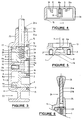
- FIGURE 1 is a side elevational view of one preferred form of the braking device illustrating its normally mounted relationship with a wheel
- FIGURE 2 is an elevational view of the mounting member for the body part of the braking device of figure 1
- FIGURE 3 is a longitudinal sectional view on line X-X of figure 1
- FIGURE 4 is a sectional view on line Y-Y of figure 1, and
- FIGURE 5 is a sectional view on lines Z-Z of figure 2
- FIGURE 6 is a fragmentary sectional view illustrating one modification of the hand grip and operating means of the first form of the invention
- FIGURE 7 is a side view of a second form of the invention with further modifications
- FIGURE 8 is a view in the direction of arrows E-E of figure 7
- FIGURE 9 is a view in the direction of arrows F-F of figure 7
- FIGURE 10 is a sectional view of the second form as viewed on line G-G of figure 7
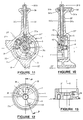
- FIGURE 11 is a sectional side view of the second form as viewed in the direction of arrows H-H of figure 8
- FIGURE 12 is a face view of the separated mounting member of the second form of the invention
- FIGURE 13 is a sectional view on line J-J of figure 12
- FIGURE 14 is a fragmentary sectional view illustrating a variation in hand grip and operating means of the second form of the invention
- FIGURE 15 is a fragmentary sectional view illustrating another variation in the hand grip and operating means of the second form of the invention
- FIGURE 16 is a side view of a third form of the invention, illustrated in the position for wheel braking under load
- FIGURE 17 is a view in the direction of arrows K-K of figure 16
- FIGURE 18 is a side view of the third form of the invention, illustrated in the normal free-wheeling position
- FIGURE 19 is a side view of the third form of the invention, illustrated in wheel braked position for parking
- FIGURE 20 is a sectional view on line L-L of figure 17
- FIGURE 21 is a face view of the separated mounting member for the third form of the invention
- FIGURE 22 is a section view on line M-M of figure 16, and
- FIGURE 23 is part-sectional view on line N-N of figure 19.
- In a typical wheelchair construction the main support wheels are of large diameter and positioned with their axis of rotation below the seat part of the chair and such that a user can readily grip upper and forward parts of the usually provided annular wheel grip for manual propelling and manoeuvering of the wheel chair. Any manual braking device would thus normally be provided adjacent the upper forward part of one of the wheels (and there would normally be a braking device for each wheel). Thus in the drawings the front part of a
wheel 23 is indicated and the arrows C and D respectively indicate the normal forward and reverse directions of rotation. In the first form of the invention according to figures 1 to 5 of the drawings, the mounting, generally indicated by thearrow 1 and shown more particularly in face view and section in figures 2, 3 and 5 is in the form of a circular bearing having a mainstrong mounting part 2 which is arranged to be fixedly secured against movement on a suitable part of a frame of the wheel chair (not shown) such as by means of a plurality of screw-threadedrecesses 3 opening to the rear face and into which mounting bolts (not shown) can be located. The outer periphery of themounting member 1 is of substantially cylindrical form and the main body part of the device, generally indicated by thearrow 5 and shown particularly in face view in figure 1 and in section in figures 3 and 4, is provided with a complementary substantiallycylindrical recess 6 whereby thebody part 5 is locatable over themounting member 1 in a slidable rotatable fit, with minimal clearance between the sliding surfaces. Thebody part 5 is rotatable relative to themounting member 1 about aconcentric axis 7 which may be defined by a retaining bolt orstud member 8 having a circularcylindrical head part 8a located within aco-axial recess 9 of themounting member 1,and having a threadedshaft 8b arranged for screw-threaded engagement in a co-axial threaded bore 10a of a centralco-axial boss part 10 projecting inwardly from anouter face wall 11 of thebody part 5, saidboss part 9 extending through aco-axial bore 12 of themounting member 1. - The
mounting member 1 andmain body part 5 can be manufactured from any suitable materials and can for example be manufactured by any suitable means from metal materials; but in a preferred form of the invention such parts are fabricated at least predominantly from a high density rigid setting plastics material resistant to corrosion and capable of withstanding stress and frequent use, and further having inherent self lubricating qualities facilitating close fitting sliding contact between the respective surfaces of themounting member 1 andbody part 5. As the braking device would be used in connection with wheel chairs subject to outdoor exposure, and as it is essential that the components remain free to operate at all times, and to further guard against internal wear and tear, various seal means can be employed to present dust or grit entering the braking device. Accordingly,annular seal rings outer recesses body part 5 and mountingmember 1 to engage and seal against outer peripheralannular flange portions 2a and 8c, respectively, of themounting member 1 and axial retaining stud head.Annular replacement bearings peripheral recess 19 of themounting member 1 and within thefirst co-axial recess 9 for receiving the retainingstud head 8a, and providing a bearing surface for the outer periphery of thecentral boss 10 of thebody part 5. Theouter seal rings mounting member 1 andbody part 5. - The
main body part 5 may have itsouter portion 20, extending from theface part 11 and surrounding or defining the mounting part receivingrecess 6, of substantially annular flange form i.e. circular, for a major part of its periphery; but with a pair of spaced peripheralbrake lock parts tyre gripping ribs 21a,22a on the arcuate outer parts thereof, the ribbed arcuate parts of the quadrant shapedbrake lock parts rotation 7. In the drawings the neutral line Y-Y is shown horizontal and the quadrant shapedlock parts rotation 7 of the body part 5 - the positioning of thebrake lock parts brake lock parts wheel 23, and with thebody part 5 rotated about itsaxis 7 relative to themounting member 1 in the direction of arrows A the upperbrake lock part 21 will be brought into engagement with the tyre periphery 23a and may be locked in such engaging position as hereinafter described; or with movement of themain body part 5 in the reverse direction of arrows B, the lower secondbrake lock part 22 can be brought into over-riding engagement with the wheel periphery 23a without locking of thebody part 5 in position; to thus permit thewheel 23 to rotate in the normal direction C for forward movement of the wheel chair, but preventing reverse directional movement D - any such reverse directional movement D drawing the secondbrake lock part 22 fully into engagement with the wheel tyre periphery 23a. This being a desirable safety measure when a wheel chair occupier is negotiating such as a hill or slope and is thus able to put the braking device into the third position to allow rotation of the wheel chair wheels in the forward direction to climb the hill, and providing automatic braking on any tendency towards rearward movement downhill. - Operation of the braking device by movement of the
main body part 5 and actuation of the locking means is arranged to be provided by means of a lever hand grip member comprising ashaft lever 24 slidably radially located in aradial bore 25a of asleeve part 25 of themain body part 5 projecting outwardly therefrom away from thebrake block parts shaft lever 24 having its outer upper end provided with ahand grip knob 26 or the like and its inner end alignable with first and secondradial recesses mounting member 1 mountingpart 2 opening to the periphery thereof, and each housing similar spring biassedplungers 29 similar in diameter to the diameter of theoperating shaft lever 24 so as to be slidably locatable within the inner end of the sleeve part bore 25a when aligned therewith. Theplungers 29 may each be hollow members outwardly biassed relative to therespective recesses suitable compression springs 30; and the arrangement and positioning of such radial spring biassedplungers 29 is such that when themain body part 5 is rotated by means of theshaft lever 24 in the direction of arrows A to the first position, thefirst plunger 29 inrecess 27 is released upwardly into the inner lower end of the sleeve bore 25a to lock thebody part 5 in this first position; and thus with the firstbrake lock part 21 in positive engagement with the tyre periphery 23a. Theplunger 29 inrecess 27 slidably moves theshaft lever 24 outwardly in so doing, and may be released from this locking position by pressure on theknob 26 to urge theshaft lever 24, and thus theplunger 29 ofrecess 27, inwardly until thefirst plunger 29 disengages from the sleeve bore 25a to permit theshaft lever 24 to be moved rearwardly in the direction of arrows B, moving the firstbrake lock member 21 out of engagement with the tyre periphery 23a. On reaching the second neutral position as shown in full in the drawings, thesecond plunger 29 inrecess 28 can be similarly permitted to slide into engagement with the inner end of the sleeve bore 25a and lock themain body part 5 and thus braking system as a whole in the neutral position allowing freedom of movement in either direction of thewheel 23 and wheel chair supported thereby. When restricted braking is required for negotiating a hill or slope, theshaft lever 24 is depressed to move thesecond plunger 29 fully back home into itsrespective recess 28 against the spring bias to allow further movement of theshaft lever 24 in the direction of arrows B to enable the secondbrake lock member 22 to be brought into over-riding engagement with the wheel periphery 23a. The direction of the arcuate ribbed portion of suchbrake lock member 22 then permitting forward movement of the wheel chair by the second brake lock member over-riding the tyre periphery 23a in the main direction C, but any tendency of the wheel to rotate in the reverse direction will cause the secondbrake lock member 22 to be drawn into full engagement with the tyre periphery 23a in preventing such reverse direction movement. Preferably, the braking device includes spring bias means e.g. such as a helical clock spring (not shown) located within an innerannular recess part 6a defined by themounting member 1 and having one end secured relative to themounting member 1 and the opposite end secured relative to themain body part 5, e.g. on an inwardly directedanchor peg 31a to normally bias the rotational movement of thebody part 5 in the direction of arrows B; so that full braking by movement in the direction of arrows A is against the spring bias, and the braking device is biassed firstly towards the neutral position and secondly towards the restrictive reverse braking position. - The
body part 5 can be provided with afirst stop member 31 projecting inwardly from itsface wall part 11 which is located between two spaced limitingstop members 32 projecting inwardly of therecess 6a of themounting part 1 to limit the extent of rotational movement of saidbody part 5 relative to the mounting part 1 - one of saidlimit stop members 32 may also serve as an anchor or abutment for one end of the biassing spring biassing rotation movement of the body part in the direction of arrows B. - The outer portion of the
sleeve part 25 can be provided with a recess for the receipt of an annular bearing and sealing ring orsleeve 33 of a suitable self lubricating plastics material, through which thelever shaft 24 is slidably engaged; and for further sealing against the entry of dust, a resilient outer collar 33a engaged with the outer bearing ring can locate about theshaft lever 24. In one modification of the first described and illustrated form of the invention, and with reference now to figure 6 of the drawings, theshaft lever 24 can be a two part construction with an innercylindrical shaft 24a slidably located within a supporting strong metalcylindrical tube sleeve 24b which is fixedly secured to and extends from thebody sleeve part 25. The inner end of theshaft 24a is located within thebore 25a and arranged to contact and depress alocking plunger 29 located therein, as before; and the outer end part of theshaft 24a has thehand grip knob 26 secured thereto with the lower or inner part ofsuch knob 26 slidably located over the outer end part of thetube sleeve 24b to enable depression relative thereto.
Referring now to figures 7 to 13 of the drawings, in a second form of the invention, the basic concepts as described with reference to figures 1 to 6 are incorporated (like parts being similarly referenced), but further modifications or variations are illustrated by way of example.
Firstly, the twobrake lock parts 21′,22′ are integrally formed on thebody part 5′ and are of similar quadrant form in side elevation with the transversetyre gripping ribs 21′a, 22′a; but are of extended transverse width to provide a greater tyre grip area, as may be required with a heavier wheel chair user and wheel chair with wider than usual tyres. Secondly the construction of mountingmember 1′ andbody part 5′, employing strong rigid plastics material(s), dispenses with theannular seals pivot bolt 8′, and sealing against dust and grit entry by way of an annularconcentric groove 15′ in thebody part 5′ shaped to slidably receive an inturned annular concentric flange orrib 2′a of the mountingmember 1′. Further variations include extension of the integrally formedbody sleeve part 25′ to merge into and define a combined lever and hand grip, the upper end orknob part 26′ of which can protrude laterally or transversely to provide a more comfortable and readily gripped handle; thebore 25′a extending fully therethrough and slidably housing aplunger release shaft 24′c (which may be tubular, and of steel as reinforcement) with an integral or fixeddepressable button 24′d at its outer end and protruding beyond theknob part 26′ for depression as required (such as by the users thumb or palm) for depression and disengagement of aplunger 29 from thebore 25a inner end. Theshaft 24′c can be retained against accidental disengagement from thesleeve 25′ by means of an inset flange orcollar 24′e on thebutton 24′d and a retaining cap or insert 26′a of theknob part 26′; the cap/insert 26′a and/orknob part 26′ being provided with arecess 26′b to accommodate movement of the flange orcollar 24′e with theshaft 24′.
A further modification illustrated in the second form of the invention is the flat end shaping of the outer end of oneplunger 29′ to maintain positive locking (e.g. for parking the wheelchair) within the body part bore 25′a until fully depressed clear of thebore 25′a; and the rounded or domed shaping of the outer end of theother plunger 29˝ so that it does not fully locate within the inner end of thebore 25′a but provides for partial locking capable of being over over-ridden to disengage from thebore 25′a inner end with sudden lever pressure or force on the combinedhand grip lever 25′, 26 without having to depress thebutton 24′d andshaft 24′c, as may be required for emergency braking of the wheelchair. Figure 14 of the drawings illustrates another modification of the first and second described and illustrated forms of the invention, with the integralbody sleeve part 25 retained relatively short and the lever arm and handgrip partly similar to that shown in figure 6 with a strongtubular metal sleeve 24′b slidably housing aplunger release shaft 24˝ (illustrated as being tubular) with an integral orfixed press button 24˝d at its upper or outer end protruding beyond and slidably located with ahandgrip knob 26˝ secured to the upper outer end of thesleeve 24′b. In this arrangement therelease shaft 24˝ can be retained against accidental disengagement from thesleeve 24′b andknob 26˝ such as by a retainingcirclip 24˝f.
In some wheelchair constructions, the location of the braking device may require that the brake lever arm be cranked or bent outwardly for convenience of operation by a user and to avoid the need for any additional linkage mechanism (which could be prone to failure or detract from desired positive and fast action). Accordingly, it is envisaged that a short strong sleeve type lever arm can be provided in the necessary or desired cranked or bent form, and a flexible or link construction inner plunger release shaft located therein. One example of this modification or variation of the invention is shown in figure 15 of the drawings and involves a fixed arcuatetubular sleeve 24‴b extending from thebody sleeve part 25 and slidably housing aplunger release shaft 24‴ made up of a series (the number being dependent upon the length and curvature of thesleeve 24‴b) of short parts conjoined by ball or 'knuckle'joints 24‴c. Theknob 26˝ andpress button 24˝d parts being as for the arrangement described with reference to figure 14 of the drawings.
Furthermore variations of the invention are envisaged and will now be described by way of example with reference to the remaining figures 16 to 23 of the accompanying drawings. In this construction a straight or curved lever arm can be employed but a curved lever arm assembly withplunger release shaft 24‴ ,knob 26˝ andpress button 24˝d part the same as or similar to those described with reference to figure 15 are illustrated. The rotational mounting arrangement of thebody part 5‴ and mountingmember 1‴ is generally similar to the second form arrangement described with reference to figures 7 to 13; but in this third form of the invention the mountingmember 1‴ has three circumferentially spacedrecesses 27′, 28′, 27˝ slidably housing three springbiassed locking plungers 29′,29˝,29‴ (two 29′ and 29‴) of which may be of similar fully locking flat outer end shape and one 29˝ of which has a rounded or domed outer end shape for partial locking and capable of being over-ridden for emergency braking as described with reference to figure 10 and 11 in particular - thepartial locking plunger 29˝ is located intermediate the two other fully lockingplungers 29′ and 29‴ , so that the device can be locked fully with either of the brake lock parts in their tyre engaging positions and partially locked with both brake lock parts clear of their tyre engaging positions.
The third construction also provides for the location of the device to one side, i.e. the inner side, of awheel 23 and the lateral projection of the tyre engaging brake lock parts transversely over the tyre or wheel periphery 23a, as may be necessary for some wheel chair constructions - and thus a cranked or outwardly projecting operating lever arm arrangement would be appropriate for convenient operation by a user. Whilst both the laterally projecting brake lock parts can be fixed relative to thedevice body part 5‴ for movement therewith and into positive locking engagement with the wheel periphery 23a; the third form of the invention further provides that onebrake locking part 21˝ is fixed relative to thebody part 5‴ e.g. integrally formed therewith, and arranged to provide for braking or locking of the wheel against rotation in either direction such as may be required for parking of the wheel chair, whilst the otherbrake locking part 22˝ can be separately formed and pivotally mounted on thebody part 5‴ for movement relative to thebody part 5‴ as well as movement with saidbody part 5‴ relative to the mountingmember 1‴ andwheel 23, to provide for self-locking engagement with the wheel periphery 23a when thewheel 23 rotates in one direction and release (on release ofplunger 29‴) from the wheel periphery when the wheel is rotated in the opposite direction. In particular the arrangement provides for full wheel braking against reverse rotation and free wheel rotational movement in a forward direction, thus facilitating the safe negotiation of an incline by the wheel chair user. As illustrated in figures 16 to 23 the first fixedbrake lock member 21˝ can be relatively small and provide for tyre engagement and wheel braking against movement in either direction under any load conditions and when the device is positioned withplunger 29′ engaged in thebore part bore 25a; whereas the second pivotedbrake lock member 22˝ is much larger and is cam shaped (oval) with aneccentric pivot axis 22˝b (defined by a mounting andpivot bolt 22˝c) and normally retained in the non-engaging position shown in full line in the drawing (such as by abiassing coil spring 33 located with arecess 34 of the cambrake lock part 2˝) but arranged so as to automatically pivot into full locking or braking engagement with the tyre or wheel periphery 23a (as shown in broken outline in figure 16) on reverse rotation of thewheel 23 in the direction of arrow D on positioning of the device with theplunger 29‴ engaged in thebody part bore 25a. In this latter position, forward rotation of thewheel 23 in the direction of arrow C will normally free the cambrake lock part 22˝ from its engagement with the wheel tyre or periphery 23a. Bothbrake locking parts 21˝ and 22˝ are again provided with engagingtransverse ribs 21˝a and 22˝a, but the outer side face 22˝c (remote from the tyre) ofpart 22˝ can be smooth.
The pivoted cam brake lock arrangement is described with reference to figures 16 to 23 and laterally projecting brake lock parts; and it will be appreciated that the same basic concept can also be applied, with appropriate modification and mounting, to a brake device arrangement aligned with the wheel instead of being located to one side of the wheel periphery.
Also, it will be appreciated various of the arrangements and modifications described and illustrated for one form of the invention may be similarly applicable (with modification or adaption as necessary) to the other forms of the invention described and illustrated by way of example. Thus, by this invention, there is provided a relatively simply constructed but safe, effective and strong braking device providing for a locked neutral position, a locked fully brake on position, and a safety restrictive reverse rotation brake position. The braking device may be simply and readily fixed to existing or new wheel chairs in the preferred form of the invention, but as previously indicated the braking device may be similarly applicable to and attached to other wheeled constructions such as a peramulator or other wheeled trolley or like vehicle; and it will be further seen that the invention may also be applicable to such as any other wheel device or to a moving surface such as the surface of an endless loop belt, or to such as a rope or cable - in the latter case, it is envisaged that the invention can have particular application in such as yachting and for the controlled but fast and effective braking releasing and hawling in of rigging or other ropes, lines, cables or the like. Whilst the braking device is particularly effective with resilient surfaces, such as wheel tyre surfaces it will be also effective for non-resilient surfaces with, if necessary, friction resistant gripping pads on the brake locking parts.
Some preferred aspects of the invention have been described and illustrated by way of example, but it will be appreciated that other variations of and modifications to the invention can take place without departing from the scope of the appended claims.
Claims (15)
- A manually operable braking device arranged for fixedly mounting in close proximity to a normally freely movable surface (23a), and including hand grip means (24,26), for controlling operation of the braking device, characterised in that said braking device comprises a stationary fixed mounting member (1) having an at least partly cylindrical bearing part (2) with an axis (7) arranged for disposition transverse to the normal direction of movement (C or D) of said surface (23a), a main body part (5) supported by said mounting member (1) for partial rotation of said body part (5) about said mounting axis (7), the body part (5) having a substantially cylindrical recess (6) within which said mounting member bearing part (2) is located as a slidable rotatable fit and the hand grip means (24,26) being mounted directly on said body part (5) for effecting said partial rotation of the body part (5) relative to the mounting member (1) between at least first and second positions, and locking means (29) associated with said hand grip means (24,26) and mounting member (1) for releasably locking said body part (5) in either of said at least first and second positions; and said body part (5) having at least one external brake lock part (21,22) projecting therefrom and arranged to engage the movable surface (23a) to prevent movement thereof when said body part (5) is moved to said first position, and said brake lock part (21,22) being movable clear of said movable surface (23a) for freedom of movement with the body part (5) in said second position.
- A braking device as claimed in claim 1, wherein said body part (5) is arranged for partial rotation by the hand grip means (24,26) and relative to the mounting member (1) between first, second and third positions, and said locking means (29) provides for releasably locking said body part (5) in any selected one of said first and second positions; and said body part (5) has two external spaced brake lock parts (21 and 22) arranged and positioned such that one of said brake lock parts (21 or 22) is positively engageable with said movable surface (23a) on movement of the body part (5) to and locking in said first position to prevent movement of said movable surface (23a) in any direction, movement of said body part (5) to and locking in said second position will position both said brake lock parts (21 and 22) clear of said movable surface (23a) for freedom of movement, and movement of said body part (5) to said third position will position the other of said brake lock parts (22 or 21) adjacent said movable surface (23a) in an over-ride position permitting movement of said movable surface in said normal direction but preventing movement of said movable surface in a reverse direction.
- A braking device as claimed in claim 2, wherein said spaced brake lock parts (21,22) are formed or provided on the periphery of the body part (5) for partial rotation therewith about said mounting axis (7) and for movement of either brake lock (21 or 22) part into or out of engagement with said movable surface (23a).
- A braking device as claimed in claim 3, wherein said brake lock parts (21,22) are fixed in relation to the body part (5) and formed integrally therewith to project substantially radially from the said body part periphery, said brake lock parts (21,22) having transversely ribbed arcuate gripping surfaces (21a, 22a) engageable with said movable surface (23a).
- A braking device as claimed in claim 2, wherein said mounting member (1) and body part (5''') are arranged for location to one side of said movable surface (23a) and said brake lock parts (21'',22'') project laterally from said body part (5''') in off-set relationship to the mounting member axis (7) and so as to extend laterally over said movable surface (23a).
- A braking device as claimed in claim 5, wherein said brake lock parts (21'',22'') are provided with transversely ribbed arcuate gripping surfaces (21''a,22''a) engageable with said movable surface (23a).
- A braking device as claimed in claim 5, wherein one (21'') of said brake lock parts (21'',22'') is fixed relative to said body part (5''') and is arranged on movement with the body into engagement with said movable surface (23a) to prevent movement in either direction of said movable surface (23a); and the other (22'') of said brake lock parts (21'',22'') is mounted for pivotal movement about an axis (22''b) parallel with said mounting member axis (7) between an engaging position engaging said movable surface (23a) to prevent movement in one direction and a disengaged or disengagable position allowing movement of said movable surface (23a) in the opposite direction or in both directions.
- A braking device as claimed in claim 1, wherein said locking means (29) comprises the provision in said mounting member bearing part (2) of two circumferentially spaced peripheral recesses (27,28) each housing a spring biassed plunger (29',29'') and either of which is alignable with an inner end of a bore (25a) of said body part (5) to engage therein and prevent or restrict rotational movement of the body part (5) relative to the mounting member (1), and hold said body part (5) with the brake lock parts (21,22) in selected positions and relationship with said movable surface (23a).
- A braking device as claimed in claim 8, wherein said mounting member bearing part (2) has a third circumferentially spaced peripheral recess (27'') housing a spring biassed plunger (29''') which can be aligned with said bore inner end (25a) to prevent or restrict rotational movement of the body part (5) relative to the mounting member (1), and hold said body part (5) with the brake lock parts (21,22) in a further selected position and relationship with said movable surface (23a).
- A braking device as claimed in claim 8 or claim 9, wherein one said plunger member (29''), which is arranged to hold the body part (5) with the brake lock parts (21,22) in non-engaging relationship with the movable surface, has its outer end part shaped to permit over-riding disengagement from the body part bore inner end (25a) when engaged therewith and on the application of force to said hand grip means (24,26) for rotational movement of the body part (5), for rapid engagement of either of said brake lock parts (21,22) with said movable surface (23a).
- A braking device as claimed in claim 8 or claim 9, wherein said body part bore (25a) slidably houses a release shaft (24) connected to a hand grip (26) of said hand grip means (24,26) and depressable by a user of the device to move the one of said plungers (29) engaged in the bore inner end (25a) inwardly of its recess against said spring bias to permit disengagement of said one plunger (29) from the bore inner end (25a), and rotational movement of the body part (5) to a next selected position with the brake lock parts (21,22) in their desired relationship with said movable surface (23a).
- A braking device as claimed in claim 11, wherein said hand grip means (24,26) is in the form of a lever part (24b,25) defined by a shaped tubular extension (24b,25) of said body part (5) communicating with said body part bore (25a),said release shaft (24c) extending through said hand grip lever part (24b,25) to have an outer end abutting or connected to a depressable button (24d) for effecting movement of said shaft (24c) to disengage said one plunger (29) from the bore inner end (25a).
- A braking device as claimed in claim 12, wherein the hand grip lever part (24b,25) is of angled or arcuate form to provide an off-set hand grip and said depressable shaft (24c) is a flexible or flexible link shaft to be slidably movable longitudinally within the bore of said angled or arcuate lever part (24b,25).
- A braking device as claimed in claim 8 or claim 9, wherein said hand grip means (24,26) comprises a lever arm (24) with a fixed shaped hand grip part (26) at its outer end, the opposite end part of said lever arm being slidably mounted within said body part bore (25a) and being arranged on depression of an inwardly directed force on the hand grip part (26) and lever arm (24) to engage and depress the plunger (29) end engaged with said bore (25a) to effect disengagement therefrom and allow rotational movement of the body part (5) by said lever arm (24) to a next selected position.
- A braking device as claimed in any one of the preceding claims and adapted as a wheel chair braking device for fixedly mounting in close proximity to the periphery of a main support wheel (23) of the wheel chair; said wheel periphery defining said normally freely movable surface (23a) with which said brake lock part or parts (21,22) is or are engageable in preventing rotation of said support wheel.
Priority Applications (1)
| Application Number | Priority Date | Filing Date | Title |
|---|---|---|---|
| AT89307670T ATE102882T1 (en) | 1988-08-01 | 1989-07-27 | BRAKING DEVICES. |
Applications Claiming Priority (2)
| Application Number | Priority Date | Filing Date | Title |
|---|---|---|---|
| NZ225630 | 1988-08-01 | ||
| NZ225630A NZ225630A (en) | 1988-08-01 | 1988-08-01 | Hand brake with two-way directional braking |
Publications (3)
| Publication Number | Publication Date |
|---|---|
| EP0353954A2 EP0353954A2 (en) | 1990-02-07 |
| EP0353954A3 EP0353954A3 (en) | 1990-12-05 |
| EP0353954B1 true EP0353954B1 (en) | 1994-03-16 |
Family
ID=19922544
Family Applications (1)
| Application Number | Title | Priority Date | Filing Date |
|---|---|---|---|
| EP89307670A Expired - Lifetime EP0353954B1 (en) | 1988-08-01 | 1989-07-27 | Improvements in and relating to braking devices |
Country Status (9)
| Country | Link |
|---|---|
| US (1) | US5029674A (en) |
| EP (1) | EP0353954B1 (en) |
| JP (1) | JPH02225832A (en) |
| KR (1) | KR900003559A (en) |
| AT (1) | ATE102882T1 (en) |
| AU (1) | AU640903B2 (en) |
| CA (1) | CA1322976C (en) |
| DE (1) | DE68913852T2 (en) |
| NZ (1) | NZ225630A (en) |
Families Citing this family (15)
| Publication number | Priority date | Publication date | Assignee | Title |
|---|---|---|---|---|
| JP2537583Y2 (en) * | 1990-10-05 | 1997-06-04 | 株式会社松永製作所 | Wheelchair parking brake device |
| JPH0724011A (en) * | 1993-05-14 | 1995-01-27 | Hirano Seiki Kogyo Kk | Manual transporting vehicle braking device and the manual transporting vehicle |
| US5538214A (en) * | 1994-07-27 | 1996-07-23 | Sinila; Alexander | Locking accessory support apparatus |
| AU668674B3 (en) * | 1995-10-11 | 1996-05-09 | Maxiwash Pty Ltd | Brake apparatus |
| JP2001247029A (en) * | 2000-03-06 | 2001-09-11 | Takahiro Kogyo Kk | Braking device |
| JP2003090362A (en) * | 2001-09-18 | 2003-03-28 | Akebono Brake Ind Co Ltd | Braking device |
| WO2003018377A1 (en) * | 2001-08-29 | 2003-03-06 | Alfred Michael Vegvary | Wheel lock apparatus |
| AU2002319018B2 (en) * | 2001-08-29 | 2006-12-07 | Alfred Michael Vegvary | Wheel lock apparatus |
| US6655503B1 (en) * | 2002-05-17 | 2003-12-02 | Thomas O. Moody | Anti-rollback brake |
| AU2003261172A1 (en) * | 2002-07-17 | 2004-02-02 | Lawrence-Nelson, Llc | Wheelchair wheel immobilizer |
| GB2434778A (en) * | 2006-02-06 | 2007-08-08 | Michael Jeffrey Spindle | Wheelchair with adjustable ride height |
| WO2010102028A1 (en) | 2009-03-03 | 2010-09-10 | Hector Melvin G | Structure, components and method for constructing and operating an automatically self locking manually propelled vehicle such as a wheel chair |
| US8096570B2 (en) * | 2009-10-19 | 2012-01-17 | Sunrise Medical (Us) Llc | Locking cable actuator |
| SI25467A (en) * | 2017-07-28 | 2019-01-31 | Jožef Stakne | Brake |
| EP3572239B1 (en) | 2018-05-23 | 2023-09-20 | Stryker Corporation | Caster assembly with brake assembly having low actuation force |
Family Cites Families (11)
| Publication number | Priority date | Publication date | Assignee | Title |
|---|---|---|---|---|
| GB1243032A (en) * | 1967-11-24 | 1971-08-18 | Wilhelm Meyer | A brake device for a conveyance |
| US4560033A (en) * | 1980-01-21 | 1985-12-24 | Julian C. Renfro | Multifunction wheelchair handbrake especially adapted for ramp climbing |
| EP0040456A1 (en) * | 1980-05-20 | 1981-11-25 | Lucas-Stichting voor Revalidatie | Brake for a rolling chair |
| GB2110780A (en) * | 1981-12-07 | 1983-06-22 | Nigel Terry Walter Platt | Wheeled vehicle fitted with a brake |
| NZ204245A (en) * | 1983-05-16 | 1986-08-08 | Palmerston North Hospital | Brake acting on resilient tyre:in operative mode brake is applied whatever direction of rotation of tyre |
| US4570756A (en) * | 1983-09-30 | 1986-02-18 | Quadra Wheelchairs, Inc. | Brake device for wheelchairs |
| US4691933A (en) * | 1984-03-06 | 1987-09-08 | Herbert Strauss | Wheelchair parking brake |
| JPS6274362A (en) * | 1985-09-28 | 1987-04-06 | 日進医療器株式会社 | Brake apparatus of wheelchair |
| DE3538535A1 (en) * | 1985-10-30 | 1987-05-07 | Alfred Giesau | PARKING BRAKE FOR WHEELCHAIR WHEELS |
| US4733755A (en) * | 1987-06-22 | 1988-03-29 | Manning Donald L | Anti-rolling device for wheelchair |
| US4887830A (en) * | 1988-03-29 | 1989-12-19 | Invacare Corporation | Wheelchair with combined wheel lock and hill holder |
-
1988
- 1988-08-01 NZ NZ225630A patent/NZ225630A/en unknown
-
1989
- 1989-07-26 CA CA000606728A patent/CA1322976C/en not_active Expired - Fee Related
- 1989-07-26 US US07/385,826 patent/US5029674A/en not_active Expired - Fee Related
- 1989-07-27 DE DE68913852T patent/DE68913852T2/en not_active Expired - Fee Related
- 1989-07-27 EP EP89307670A patent/EP0353954B1/en not_active Expired - Lifetime
- 1989-07-27 AT AT89307670T patent/ATE102882T1/en active
- 1989-08-01 JP JP1198109A patent/JPH02225832A/en active Pending
- 1989-08-01 AU AU39195/89A patent/AU640903B2/en not_active Ceased
- 1989-08-01 KR KR1019890011001A patent/KR900003559A/en not_active Abandoned
Also Published As
| Publication number | Publication date |
|---|---|
| AU3919589A (en) | 1990-02-08 |
| CA1322976C (en) | 1993-10-12 |
| US5029674A (en) | 1991-07-09 |
| DE68913852T2 (en) | 1994-06-30 |
| KR900003559A (en) | 1990-03-26 |
| NZ225630A (en) | 1991-03-26 |
| AU640903B2 (en) | 1993-09-09 |
| EP0353954A3 (en) | 1990-12-05 |
| ATE102882T1 (en) | 1994-04-15 |
| JPH02225832A (en) | 1990-09-07 |
| DE68913852D1 (en) | 1994-04-21 |
| EP0353954A2 (en) | 1990-02-07 |
Similar Documents
| Publication | Publication Date | Title |
|---|---|---|
| US5029674A (en) | Braking devices | |
| US4354691A (en) | Wheel chair propulsion system | |
| US5896779A (en) | Dual mode brake actuator for walker | |
| US5799756A (en) | Surelock wheelchair brakes | |
| US4677706A (en) | Castor brake | |
| US4354398A (en) | Control mechanism for hydraulic locking device | |
| US4758013A (en) | Hand crank wheelchair drive | |
| US6298950B1 (en) | Steering roller | |
| US4538825A (en) | Wheelchair anti-rollback mechanism | |
| US6024331A (en) | Rod-mounted holder bracket for hand shower | |
| US6219881B1 (en) | Brake for caster | |
| US2631470A (en) | Straight pull brake lever structure | |
| US5370017A (en) | Handlebar cable control with biased return feature | |
| US20070024020A1 (en) | Propulsion aid | |
| US6464044B2 (en) | Braking apparatus wherein working and non-working states are established by controlling rotation of cam | |
| US5398912A (en) | Hoist including brake cover and operating lever coupling | |
| GB2203209A (en) | Bowden mechanisms | |
| US5626058A (en) | Rotary actuator for a bicycle brake | |
| EP0337320B1 (en) | Automatic adjuster releasing apparatus for drum brake | |
| KR20180125837A (en) | Wheel slip prevention device for wheelchair | |
| JPS62227847A (en) | Spring brake cylinder | |
| EP0148181B1 (en) | Brake device for a cycle | |
| GB2237350A (en) | Clutch control device | |
| JPS6239773B2 (en) | ||
| EP0084294B1 (en) | Actuator for controlling the brakes of railway vehicles and the like, incorporating an automatic device for taking up play |
Legal Events
| Date | Code | Title | Description |
|---|---|---|---|
| PUAI | Public reference made under article 153(3) epc to a published international application that has entered the european phase |
Free format text: ORIGINAL CODE: 0009012 |
|
| AK | Designated contracting states |
Kind code of ref document: A2 Designated state(s): AT BE CH DE ES FR GB GR IT LI LU NL SE |
|
| PUAL | Search report despatched |
Free format text: ORIGINAL CODE: 0009013 |
|
| AK | Designated contracting states |
Kind code of ref document: A3 Designated state(s): AT BE CH DE ES FR GB GR IT LI LU NL SE |
|
| 17P | Request for examination filed |
Effective date: 19901220 |
|
| 17Q | First examination report despatched |
Effective date: 19920210 |
|
| GRAA | (expected) grant |
Free format text: ORIGINAL CODE: 0009210 |
|
| AK | Designated contracting states |
Kind code of ref document: B1 Designated state(s): AT BE CH DE ES FR GB GR IT LI LU NL SE |
|
| PG25 | Lapsed in a contracting state [announced via postgrant information from national office to epo] |
Ref country code: IT Free format text: LAPSE BECAUSE OF FAILURE TO SUBMIT A TRANSLATION OF THE DESCRIPTION OR TO PAY THE FEE WITHIN THE PRE;WARNING: LAPSES OF ITALIAN PATENTS WITH EFFECTIVE DATE BEFORE 2007 MAY HAVE OCCURRED AT ANY TIME BEFORE 2007. THE CORRECT EFFECTIVE DATE MAY BE DIFFERENT FROM THE ONE RECORDED.SCRIBED TIME-LIMIT Effective date: 19940316 Ref country code: AT Effective date: 19940316 Ref country code: ES Free format text: THE PATENT HAS BEEN ANNULLED BY A DECISION OF A NATIONAL AUTHORITY Effective date: 19940316 Ref country code: SE Free format text: THE PATENT HAS BEEN ANNULLED BY A DECISION OF A NATIONAL AUTHORITY Effective date: 19940316 Ref country code: NL Effective date: 19940316 Ref country code: GR Free format text: LAPSE BECAUSE OF FAILURE TO SUBMIT A TRANSLATION OF THE DESCRIPTION OR TO PAY THE FEE WITHIN THE PRESCRIBED TIME-LIMIT Effective date: 19940316 |
|
| REF | Corresponds to: |
Ref document number: 102882 Country of ref document: AT Date of ref document: 19940415 Kind code of ref document: T |
|
| REF | Corresponds to: |
Ref document number: 68913852 Country of ref document: DE Date of ref document: 19940421 |
|
| ET | Fr: translation filed | ||
| PGFP | Annual fee paid to national office [announced via postgrant information from national office to epo] |
Ref country code: GB Payment date: 19940722 Year of fee payment: 6 |
|
| PGFP | Annual fee paid to national office [announced via postgrant information from national office to epo] |
Ref country code: CH Payment date: 19940727 Year of fee payment: 6 |
|
| PGFP | Annual fee paid to national office [announced via postgrant information from national office to epo] |
Ref country code: BE Payment date: 19940728 Year of fee payment: 6 |
|
| PGFP | Annual fee paid to national office [announced via postgrant information from national office to epo] |
Ref country code: FR Payment date: 19940729 Year of fee payment: 6 |
|
| PG25 | Lapsed in a contracting state [announced via postgrant information from national office to epo] |
Ref country code: LU Free format text: LAPSE BECAUSE OF NON-PAYMENT OF DUE FEES Effective date: 19940731 |
|
| NLV1 | Nl: lapsed or annulled due to failure to fulfill the requirements of art. 29p and 29m of the patents act | ||
| PGFP | Annual fee paid to national office [announced via postgrant information from national office to epo] |
Ref country code: DE Payment date: 19940923 Year of fee payment: 6 |
|
| PLBE | No opposition filed within time limit |
Free format text: ORIGINAL CODE: 0009261 |
|
| STAA | Information on the status of an ep patent application or granted ep patent |
Free format text: STATUS: NO OPPOSITION FILED WITHIN TIME LIMIT |
|
| 26N | No opposition filed | ||
| PG25 | Lapsed in a contracting state [announced via postgrant information from national office to epo] |
Ref country code: GB Effective date: 19950727 |
|
| PG25 | Lapsed in a contracting state [announced via postgrant information from national office to epo] |
Ref country code: CH Effective date: 19950731 Ref country code: LI Effective date: 19950731 Ref country code: BE Effective date: 19950731 |
|
| BERE | Be: lapsed |
Owner name: BOYES PAUL DAVID Effective date: 19950731 Owner name: BOYES BARRIE JOHN Effective date: 19950731 |
|
| REG | Reference to a national code |
Ref country code: CH Ref legal event code: PL |
|
| GBPC | Gb: european patent ceased through non-payment of renewal fee |
Effective date: 19950727 |
|
| PG25 | Lapsed in a contracting state [announced via postgrant information from national office to epo] |
Ref country code: DE Effective date: 19960402 |
|
| PG25 | Lapsed in a contracting state [announced via postgrant information from national office to epo] |
Ref country code: FR Effective date: 19960430 |
|
| REG | Reference to a national code |
Ref country code: FR Ref legal event code: ST |
|
| REG | Reference to a national code |
Ref country code: FR Ref legal event code: ST |
|
| REG | Reference to a national code |
Ref country code: FR Ref legal event code: ST |