EP0353597B1 - Metal mold exchanging apparatus for use in injection molding machines - Google Patents
Metal mold exchanging apparatus for use in injection molding machines Download PDFInfo
- Publication number
- EP0353597B1 EP0353597B1 EP89113665A EP89113665A EP0353597B1 EP 0353597 B1 EP0353597 B1 EP 0353597B1 EP 89113665 A EP89113665 A EP 89113665A EP 89113665 A EP89113665 A EP 89113665A EP 0353597 B1 EP0353597 B1 EP 0353597B1
- Authority
- EP
- European Patent Office
- Prior art keywords
- metal mold
- injection molding
- molding machine
- swingable
- height
- Prior art date
- Legal status (The legal status is an assumption and is not a legal conclusion. Google has not performed a legal analysis and makes no representation as to the accuracy of the status listed.)
- Expired - Lifetime
Links
- 239000002184 metal Substances 0.000 title claims description 181
- 238000001746 injection moulding Methods 0.000 title claims description 64
- 238000009877 rendering Methods 0.000 claims description 2
- 238000012546 transfer Methods 0.000 description 22
- 238000010276 construction Methods 0.000 description 10
- 230000007246 mechanism Effects 0.000 description 9
- 238000012423 maintenance Methods 0.000 description 5
- 238000000034 method Methods 0.000 description 4
- 238000000465 moulding Methods 0.000 description 4
- 230000008859 change Effects 0.000 description 3
- 238000004519 manufacturing process Methods 0.000 description 3
- 230000001174 ascending effect Effects 0.000 description 2
- 230000003247 decreasing effect Effects 0.000 description 2
- 230000003028 elevating effect Effects 0.000 description 2
- 238000009434 installation Methods 0.000 description 2
- 230000004048 modification Effects 0.000 description 2
- 238000012986 modification Methods 0.000 description 2
- 239000002994 raw material Substances 0.000 description 2
- 238000006073 displacement reaction Methods 0.000 description 1
- 230000005484 gravity Effects 0.000 description 1
- 238000010438 heat treatment Methods 0.000 description 1
- 238000010348 incorporation Methods 0.000 description 1
- 230000000977 initiatory effect Effects 0.000 description 1
- 238000002347 injection Methods 0.000 description 1
- 239000007924 injection Substances 0.000 description 1
- 230000008569 process Effects 0.000 description 1
- 230000004044 response Effects 0.000 description 1
- 238000005096 rolling process Methods 0.000 description 1
- XLYOFNOQVPJJNP-UHFFFAOYSA-N water Substances O XLYOFNOQVPJJNP-UHFFFAOYSA-N 0.000 description 1
Images



Classifications
-
- B—PERFORMING OPERATIONS; TRANSPORTING
- B30—PRESSES
- B30B—PRESSES IN GENERAL
- B30B15/00—Details of, or accessories for, presses; Auxiliary measures in connection with pressing
- B30B15/30—Feeding material to presses
-
- B—PERFORMING OPERATIONS; TRANSPORTING
- B29—WORKING OF PLASTICS; WORKING OF SUBSTANCES IN A PLASTIC STATE IN GENERAL
- B29C—SHAPING OR JOINING OF PLASTICS; SHAPING OF MATERIAL IN A PLASTIC STATE, NOT OTHERWISE PROVIDED FOR; AFTER-TREATMENT OF THE SHAPED PRODUCTS, e.g. REPAIRING
- B29C45/00—Injection moulding, i.e. forcing the required volume of moulding material through a nozzle into a closed mould; Apparatus therefor
- B29C45/14—Injection moulding, i.e. forcing the required volume of moulding material through a nozzle into a closed mould; Apparatus therefor incorporating preformed parts or layers, e.g. injection moulding around inserts or for coating articles
- B29C45/14549—Coating rod-like, wire-like or belt-like articles
-
- B—PERFORMING OPERATIONS; TRANSPORTING
- B29—WORKING OF PLASTICS; WORKING OF SUBSTANCES IN A PLASTIC STATE IN GENERAL
- B29C—SHAPING OR JOINING OF PLASTICS; SHAPING OF MATERIAL IN A PLASTIC STATE, NOT OTHERWISE PROVIDED FOR; AFTER-TREATMENT OF THE SHAPED PRODUCTS, e.g. REPAIRING
- B29C45/00—Injection moulding, i.e. forcing the required volume of moulding material through a nozzle into a closed mould; Apparatus therefor
- B29C45/17—Component parts, details or accessories; Auxiliary operations
- B29C45/1756—Handling of moulds or mould parts, e.g. mould exchanging means
Definitions
- This invention relates to metal mold exchanging apparatus for use in an injection molding machine, and more particularly an injection molding machine of the horizontal mold clamping type in which the metal molds are opened and closed in the horizontal direction and the metal molds are loaded and unloaded from the injection molding machine from one side thereof.
- a plurality of injection molding machines 1 are juxtaposed in their longitudinal directions, rails 2 are installed on one side of the injection molding machines and the metal molds are exchanged by a single metal mold exchanging machine 3 running on the rails 2.
- a plurality of injection molding machines 1 are juxtaposed in their width direction, a metal mold exchanging machine 3 is installed for each or two injection molding machines, and the loading and unloading of metal mold 4 are performed from one side of each injection molding machine.
- metal mold 4 is required to be preheated, it is necessary to install preheating device 5 between adjacent injection molding machines 1. Moreover, in accordance with the process administration of each injection molding machine it is necessary to perform various process steps in a predetermined manner such as conveyance of the metal mold 4 to the preheating device 5, initiation and termination of the heating, conveyance of the mold exchanging machine 3, movement of the injection molding machine and exchange of the metal mold, which complicates the operation and requires a space for the preheating device 5. Moreover it is difficult to change the layout of the machines.
- the metal mold exchanging apparatus are spaced in the longitudinal direction of the injection molding machines by a distance between a position to which a used (old) metal mold is brought and a position to which a new metal mold to be used next is brought (see Fig. 8), where metal molds are transferred along rails, it is not only expensive but also the control of transfer is difficult. Moreover, change of the machine layout is not easy because of a complicated foundation work. It has been proposed to fix the metal mold exchanging apparatus 3 to the floor surface so as to move only the upper portion of the metal mold exchanging apparatus. Although this construction is of relatively low cost, since the metal mold exchanging apparatus is moved to the injection side, the metal mold exchanging apparatus interferes the movement of the injection molding machine.
- Another object of this invention is to provide a novel metal mold exchanging apparatus capable of preheating the metal mold with a simple method.
- a further object of this invention is to provide a novel metal mold exchanging apparatus for use in an injection molding machine capable of satisfying a system demand without changing the basic construction of the machine not only in a full automatic operation but also in a manual operation.
- a novel metal mold exchanging apparatus for use in an injection molding machine including a stationary die plate, a movable die plate and means for moving the movable die plate, wherein a metal mold is loaded on and unloaded from the injection molding machine, characterized by comprising a metal mold loading and unloading unit including two metal mold supporting means which are vertically spaced with a predetermined distance therebetween, and elevator means for simultaneously raising or lowering the two metal mold supporting means for rendering a height of each one of the metal mold supporting means to be equal to a height of a position at which the metal mold is exchanged.
- a horizontal type injection molding machine in which metal molds are opened and closed in the horizontal direction is designated by a reference numeral 11 and constituted by a stationary die plate 12 supporting a stationary metal mold, a movable die plate 13 supporting a movable metal mold, and an operating mechanism 14 for reciprocating the movable die plate.
- a plurality of injection molding machines 11 are disposed side by side with predetermined spacings therebetween.
- a stationary or movable metal mold loading and unloading unit 16 which loads and unloads a metal mold 15 (including the stationary and movable molds) onto and from the injection molding machine.
- the metal mold loading and unloading unit 16 includes two vertically spaced metal mold supporting plates 17 and 18.
- a plurality of spaced apart driving rollers 26 are disposed on respective metal mold supporting plates 17 and 18 for loading and unloading the metal mold 15 supported by the supporting plates 17 and 18 onto and from an injection molding machine.
- a stopping mechanism is provided for respective supporting plates for stopping the metal mold 15.
- a new metal mold is mounted on the upper metal mold supporting plate 17 by using a crane or a carriage, not shown.
- the elevator driving device 25 is started for elevating the metal mold supporting plates 17 and 18 to the upper limit point of an elevator 19 so as to bring the lower metal mold supporting plate 18 to the same level or the metal mold exchanging level of the injection molding machine 11. Then a used (or old) metal mold 15 is transferred from the injection molding machine 11 to the lower metal mold supporting plate 18.
- a preheater (not shown) is mounted on the upper metal mold supporting plate 17 so as to preheat the new metal mold while the old metal mold is being unloaded from the injection molding machine.
- the elevating driving device 25 is operated in the opposite direction so as to lower the metal mold supporting plates 17 and 18 to the lower most point of the elevator 19 whereby the height of the upper metal mold supporting plate 17 becomes equal to the metal mold exchanging level of the injection molding machine. Then the new metal mold 15 or the supporting plate 19 is loaded on the injection molding machine.
- the metal mold 15 is exchanged by raising or lowering it, there is no fear of displacing the metal mold in the longitudinal direction of the injection molding machine, thus facilitating maintenance.
- the positions of both metal mold supporting plates 17 and 18 are determined by the upper and lower most positions of the stroke of the elevator 19. Especially, since the lower most position can be determined by gravity the positionings of the metal mold supporting plate 17 and 18 can be made readily.
- Adjusting of the metal mold temperature and the preheating temperature thereof can be made readily. More particularly, the temperature adjusting operation can be simplified where the preheating is made by manual or automatic means, then the preheated metal mold is loaded on the injection molding machine and the set temperature of temperature adjuster is switched from the preheating temperature to the molding temperature.
- Figs. 5 through 9 show a second embodiment of this invention which is different from the first embodiment in that the metal mold loading and unloading unit 16 is substituted by a swingable loading and unloading unit 30 constituted by a swingable table 31 and a transfer table 32.
- the swingable table 31 comprises a base 33 fixed to or movably mounted on the floor surface, a vertical shaft 34 secured to the base 33 and a horizontal table 35 swingable about shaft 34 by an angle of about 90.
- the table 35 is swung by an electric motor 36 mounted on the upper end of the shaft 34 for positioning the metal mold 15 mounted on the table 35 in a loading and unloading direction, and a transfer direction perpendicular thereto.
- the height of table 35 is set to be the same as the metal mold exchanging height of the injection molding machine 11, and on the upper surface of the table 35 are disposed driving rollers 37 and the stopping mechanism (not shown) corresponding to those used in the first embodiment.
- the transfer table 32 is disposed between the swingable table 31 and one end of the injection molding machine 11 and the height of its upper surface is the same as that of the table 35.
- On the upper surface of the transfer table 32 are provided a plurality of drive rollers 38 and a stopping mechanism (not shown) for stopping the metal mold 15. Furthermore, as shown in Fig. 7 the metal mold 15 on the carriage 32 is conveyed in the longitudinal direction of the injection molding machine onto the turn table 31.
- the second embodiment operates as follows.
- a new metal mold 15 is mounted on transfer table 32 by using carriage 39, as shown in Fig. 7. Mounting of the new metal mold 15 on the transfer table may be effected with a crane or a forklift.
- the motor 36 is rotated in the opposite direction so as to swing the rotary table 35 by about 90° toward the transfer table 32. Then the new metal mold 15 on the transfer table 32 is mounted on the rotary table 35.
- the swingable table 31 is used for changing the orientation of the metal mold 15 so that it is possible to change the orientation of the metal mold 15, whereby the spacing between adjacent injection molding machines 11 may be small enough to accommodate the carriage therebetween, thus increasing the space factor. Since the swingable table 31 is not moved to the side opposite to the operating side of the injection molding machine 11, the maintenance of the machine becomes easy.
- Figs. 10 through 17 illustrate the third embodiment of this invention which is different from the first embodiment in that instead of using the metal mold loading and unloading unit 16, there are provided a metal mold loading and unloading unit 40 including the swingable table 41, two vertically spaced metal mold supporting plates 42 and 43, and an elevator 44 for simultaneously ascending or descending both supporting plates 42 and 43 and a roller transfer table 45.
- the swingable table 41 comprises a vertical shaft 47, a base 46 secured to or movable on the floor surface, not shown, a swingable plate 48 swingable in the horizontal direction by an angle of about 90° about the vertical shaft 47, a driving motor 49 for swinging the shaft 47 and wheels 50 mounted on the lower surface of the swingable plate 48 and rolling on the upper surface of the base 46.
- a driving motor 49 for swinging the shaft 47 and wheels 50 mounted on the lower surface of the swingable plate 48 and rolling on the upper surface of the base 46.
- On the upper surface of the swingable plate 48 are provided drive rollers 51 and a stopping mechanism, not shown.
- the swingable table 41 is constructed to have the same function as the swingable table 31 of the second embodiment described above.
- the metal mold supporting plates 42 and 43 are simultaneously ascended and descended by an elevator 44.
- the height of the metal mold supporting plate 43 would be the same as that of the swingable table and that of the transfer table 45 to be described later, whereas at the lower most position of the elevator 44, the height of the metal mold supporting plate would be the same as that of the swingable table 48 and the transfer table 45.
- the transfer table 45 is disposed along the injection molding machine and between positions at which both metal mold supporting plates 42 and 43 and the travelling path of the carriage 39.
- On the upper surface of the carriage 39 are installed a plurality of drive rollers 53 and a stopping mechanism (not shown) for the metal mold 15.
- the transfer table 45 of this embodiment has the same construction as the transfer table 32 of the second embodiment.
- reference numeral 39a designates drive rollers disposed on the surface of the carriage 39.
- Other constructions of this embodiment are identical to that of the first embodiment.
- the third embodiment operates as follows.
- a new metal mold 15 on the carriage 39 is transferred onto the transfer table 45 and then both metal mold supporting plates 42 and 43 are lowered to the lower most position with the elevator 44. Then as shown in Figs. 12 and 13, the new metal mold 15 on the transfer table 45 is transferred onto the upper metal mold supporting plate 42.
- the swingable table 41 Concurrently therewith, or a little before or after, the swingable table 41 is swung toward the injection molding machine for unloading the old metal mold 15 from the injection molding machine 11 and then mounting the unloaded metal mold on the swingable table.
- both metal mold supporting plates 42 and 43 are raised to their uppermost positions with elevator 44. Thereafter, as shown in Figs. 16 and 17 the swingable table 41 is swung toward the metal mold supporting plates 42 and 43. Then the old metal mold 15 on the swingable table 41 is transferred onto the carriage 39 via lower metal mold supporting plate 43 and transfer table 45.
- both mold supporting plates 42 and 43 are lowered to the lower most position and the new metal mold 15 on the metal mold supporting plate 42 is transferred onto the swingable table 41. Then the swingable table 41 is swung toward the injection molding machine 11 for loading the new metal mold on the injection molding machine.
- the number of metal mold exchanging operations is small and moreover since the exchanging operation is extremely simple it is possible to reduce the metal mold exchanging time.
- the space in which the metal molds are exchanged extends in the longitudinal direction of the injection molding machine 11 and since the space is required to be provided on the side of the metal mold clamping device, it is convenient for maintenance.
- Figs. 20 through 23 illustrate the fourth embodiment of this invention which is different from the first embodiment in that instead of using the metal mold loading unit 16, a metal mold loading and unloading unit 60 is used comprising a swingable table 61, an elevator 62 for raising and lowering the swingable table 61 and two vertically spaced metal mold supporting plates 63 and 64.
- the swingable table 61 comprises a swingable table 66 which is swingable by about 90° in the horizontal direction about a shaft 65, the swingable table 66 being driven by an electric motor, not shown.
- On the upper surface of the swingable table 66 are mounted drive rollers 67 and a stopping mechanism, not shown, of the metal mold 15.
- the elevator 62 comprises a base 68 fixed to or adjustably fixed to the floor, four vertical guide bars 64 at four corners of the base 68, an elevator cage 70 raised and lowered along guide bars 69, and a driving apparatus 71 for driving the elevator cage 70, wherein the swingable table 61 is mounted on the elevator cage 70.
- the height of the swingable table 61 at the upper most position of the elevator 62 is selected to be equal to that of the upper surface of the upper metal mold supporting plate 63 to be described later 63, whereas at the lower most position of the elevator 62 would be equal to that of the upper surface of the metal mold supporting plate 64 and the metal mold exchange height of the injection molding machine 11.
- the metal mold supporting stations 63 and 64 are disposed along the injection molding machines 11 between the swingable table 61 and the path of the carriage 39 and on the upper surface of each one of the metal mold supporting stations 63 and 64 are provided drive rollers 72 and a stopping mechanism, not shown, for the metal mold 15.
- the fourth embodiment operates as follows: At the time of exchanging the metal mold 15, a new metal mold 15 is firstly mounted on the upper metal mold supporting plate 63. Concurrently therewith or shortly before or after, the swingable table 61 is swung toward the metal mold supporting plates 63 and 64 for transferring an old metal mold 15 on the swingable table 61 onto the lower metal mold supporting plate 64.
- the swingable table 61 is raised to the upper most position with the elevator 62 for transferring the metal mold 15 on the upper metal mold supporting station 63 onto the swingable table 61. Then the swingable table 61 is lowered to the lower most position with the elevator 62.
- the swingable table 61 is swung toward the injection molding machine 11 for loading the new metal mold 15 on the swingable table 61 on the injection molding machine 11.
- the space occupied by the machine can be decreased, thus increasing the efficient floor space in the factory. Furthermore since the metal molds are exchanged on the upper and lower sides it is not necessary to displace the metal mold in the longitudinal direction of the injection molding machine 11 and to provide a space for the displacement thus making easy maintenance of the injection molding machine 11. Furthermore as the metal mold exchanging operation is simple, metal mold exchanging operation control becomes easy.
- the metal mold can be readily heated by hot water or electric heater.
- the upper and lower metal mold supporting plates 63 and 64 can be elongated, and a plurality of metal molds 15 can be used in accordance with a production plan. In this case, where the number of waiting metal molds is counted, the entire production plan can be effected with this number of the metal molds.
Landscapes
- Engineering & Computer Science (AREA)
- Mechanical Engineering (AREA)
- Manufacturing & Machinery (AREA)
- Moulds For Moulding Plastics Or The Like (AREA)
- Injection Moulding Of Plastics Or The Like (AREA)
- Mounting, Exchange, And Manufacturing Of Dies (AREA)
Description
- This invention relates to metal mold exchanging apparatus for use in an injection molding machine, and more particularly an injection molding machine of the horizontal mold clamping type in which the metal molds are opened and closed in the horizontal direction and the metal molds are loaded and unloaded from the injection molding machine from one side thereof.
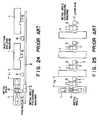
- In prior art metal mold exchanging apparatus of the type described above, as shown in Fig. 24, a plurality of
injection molding machines 1 are juxtaposed in their longitudinal directions,rails 2 are installed on one side of the injection molding machines and the metal molds are exchanged by a single metalmold exchanging machine 3 running on therails 2. Alternatively, as shown in Fig. 25, a plurality ofinjection molding machines 1 are juxtaposed in their width direction, a metalmold exchanging machine 3 is installed for each or two injection molding machines, and the loading and unloading ofmetal mold 4 are performed from one side of each injection molding machine. - In the series type prior art mold exchange machine shown in Fig. 24, it is necessary to separate adjacent injection molding machines by a definite spacing ℓ₁ for facilitating maintenance of the
injection molding machines 1 so that the total length of a series of injection molding machines becomes long with the result that when automating raw material supply the length of conveyance of the raw material becomes unequal. - Furthermore as shown in Fig. 24 it is necessary to provide
transfer rollers 5 formetal mold 4 between the metalmold exchanging machine 3 and theinjection molding machine 1, which not only increases the total length of the injection molding machine installation, but also increases the floor space of the installation. - Where
metal mold 4 is required to be preheated, it is necessary to installpreheating device 5 between adjacentinjection molding machines 1. Moreover, in accordance with the process administration of each injection molding machine it is necessary to perform various process steps in a predetermined manner such as conveyance of themetal mold 4 to the preheatingdevice 5, initiation and termination of the heating, conveyance of themold exchanging machine 3, movement of the injection molding machine and exchange of the metal mold, which complicates the operation and requires a space for thepreheating device 5. Moreover it is difficult to change the layout of the machines. - In the prior art parallel type metal mold exchanging apparatus shown in Fig. 25, it is not easy to automate the entire molding factory, especially when the
metal mold 4 is conveyed to the metal mold exchanging apparatus with a crane. Where themetal mold 4 is conveyed with acarriage 7 as shown in Fig. 25, it is not only difficult to automatically transfer the metal mold from thecarriage 7 to the metalmold exchanging apparatus 3 but also difficult to automatically control thecarriage 7. Furthermore, where thecarriages 7 are used, it is necessary to parallelly position the carriages on the sides of the metalmold exchanging apparatus 3 opposite to the molding machines so that it is necessary to increase the distance ℓ₂ between adjacent molding machines, thus increasing the entire floor space. - Furthermore, as the metal mold exchanging apparatus are spaced in the longitudinal direction of the injection molding machines by a distance between a position to which a used (old) metal mold is brought and a position to which a new metal mold to be used next is brought (see Fig. 8), where metal molds are transferred along rails, it is not only expensive but also the control of transfer is difficult. Moreover, change of the machine layout is not easy because of a complicated foundation work. It has been proposed to fix the metal
mold exchanging apparatus 3 to the floor surface so as to move only the upper portion of the metal mold exchanging apparatus. Although this construction is of relatively low cost, since the metal mold exchanging apparatus is moved to the injection side, the metal mold exchanging apparatus interferes the movement of the injection molding machine. - It is an object of this invention to provide novel metal mold exchanging apparatus for use in an injection molding machine capable of increasing the number of injection molding machines per unit area thereby improving effective utilization of the space.
- Another object of this invention is to provide a novel metal mold exchanging apparatus capable of preheating the metal mold with a simple method.
- A further object of this invention is to provide a novel metal mold exchanging apparatus for use in an injection molding machine capable of satisfying a system demand without changing the basic construction of the machine not only in a full automatic operation but also in a manual operation.
- According to this invention there is provided a novel metal mold exchanging apparatus for use in an injection molding machine including a stationary die plate, a movable die plate and means for moving the movable die plate, wherein a metal mold is loaded on and unloaded from the injection molding machine, characterized by comprising a metal mold loading and unloading unit including two metal mold supporting means which are vertically spaced with a predetermined distance therebetween, and elevator means for simultaneously raising or lowering the two metal mold supporting means for rendering a height of each one of the metal mold supporting means to be equal to a height of a position at which the metal mold is exchanged.
- In the accompanying drawings:
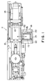
- Fig. 1 is a plan view showing injection molding machines utilizing the metal mold exchanging apparatus according to this invention;
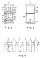
- Fig. 2 is a front view showing a loading and unloading unit of a metal mold;
- Fig. 3 is a side view showing an elevator as viewed from the lefthand side of Fig. 2;
- Fig. 4 is a diagrammatic representation of a machine array of a first embodiment of this invention shown in Fig. 1;
- Fig. 5 is a plan view showing a second embodiment of this invention;
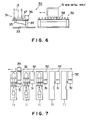
- Fig. 6 is a front view showing the construction of a metal mold loading and unloading device utilized in the second embodiment shown in Fig. 5;
- Fig. 7 is a diagrammatic representation showing the machine layout of the second embodiment of this invention shown in Fig. 5;
- Figs. 8 and 9 are plan views showing the operation of the second embodiment shown in Fig. 5;
- Fig. 10 is a plan view showing the third embodiment of this invention;
- Fig. 11 is a front view showing the construction of the metal mold loading and unloading unit;
- Figs. 12 through 17 are plan views showing the operation of the third embodiment of this invention shown in Fig. 10;
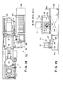
- Fig. 18 is a plan view showing a modification of the third embodiment;
- Fig. 19 is a plan view showing another modification of this invention;
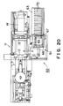
- Fig. 20 is a plan view showing the fourth embodiment of this invention;
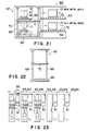
- Fig. 21 is a front view of the metal mold loading and unloading unit utilized in the fourth embodiment of this invention;
- Fig. 22 is a side view showing the table elevator as viewed from the lefthand side of Fig. 21;
- Fig. 23 is a diagrammatic representation showing a machine layout of the fourth embodiment of this invention; and
- Figs. 24 and 25 are plan views showing prior art machine layouts of different type.
- A first embodiment of this invention will now be described with reference to Figs. 1 through 4.
- In these figures a horizontal type injection molding machine in which metal molds are opened and closed in the horizontal direction is designated by a reference numeral 11 and constituted by a
stationary die plate 12 supporting a stationary metal mold, amovable die plate 13 supporting a movable metal mold, and anoperating mechanism 14 for reciprocating the movable die plate. As shown in Fig. 4, a plurality of injection molding machines 11 are disposed side by side with predetermined spacings therebetween. On one side of each injection molding machine 11, is installed a stationary or movable metal mold loading and unloadingunit 16 which loads and unloads a metal mold 15 (including the stationary and movable molds) onto and from the injection molding machine. - As shown in Figs. 2 and 3 the metal mold loading and unloading
unit 16 includes two vertically spaced metalmold supporting plates - As shown in Figs. 1 and 2, a plurality of spaced apart
driving rollers 26 are disposed on respective metalmold supporting plates metal mold 15 supported by the supportingplates metal mold 15. - In operation, for loading and unloading the metal mold, a new metal mold is mounted on the upper metal
mold supporting plate 17 by using a crane or a carriage, not shown. - The
elevator driving device 25 is started for elevating the metalmold supporting plates elevator 19 so as to bring the lower metalmold supporting plate 18 to the same level or the metal mold exchanging level of the injection molding machine 11. Then a used (or old)metal mold 15 is transferred from the injection molding machine 11 to the lower metalmold supporting plate 18. - When it is desired to preheat a new metal mold, a preheater (not shown) is mounted on the upper metal
mold supporting plate 17 so as to preheat the new metal mold while the old metal mold is being unloaded from the injection molding machine. With this measure, the preheating and unloading of the metal mold can be made at the same time, thus eliminating a preheating time independent of the unloading time. - Then the
elevating driving device 25 is operated in the opposite direction so as to lower the metalmold supporting plates elevator 19 whereby the height of the upper metalmold supporting plate 17 becomes equal to the metal mold exchanging level of the injection molding machine. Then thenew metal mold 15 or the supportingplate 19 is loaded on the injection molding machine. - As above described, since the
metal mold 15 is exchanged by raising or lowering it, there is no fear of displacing the metal mold in the longitudinal direction of the injection molding machine, thus facilitating maintenance. - The positions of both metal
mold supporting plates elevator 19. Especially, since the lower most position can be determined by gravity the positionings of the metalmold supporting plate - Adjusting of the metal mold temperature and the preheating temperature thereof can be made readily. More particularly, the temperature adjusting operation can be simplified where the preheating is made by manual or automatic means, then the preheated metal mold is loaded on the injection molding machine and the set temperature of temperature adjuster is switched from the preheating temperature to the molding temperature.
- Figs. 5 through 9 show a second embodiment of this invention which is different from the first embodiment in that the metal mold loading and
unloading unit 16 is substituted by a swingable loading and unloadingunit 30 constituted by a swingable table 31 and a transfer table 32. - As shown in Figs. 5 and 6 the swingable table 31 comprises a
base 33 fixed to or movably mounted on the floor surface, avertical shaft 34 secured to thebase 33 and a horizontal table 35 swingable aboutshaft 34 by an angle of about 90. The table 35 is swung by anelectric motor 36 mounted on the upper end of theshaft 34 for positioning themetal mold 15 mounted on the table 35 in a loading and unloading direction, and a transfer direction perpendicular thereto. - The height of table 35 is set to be the same as the metal mold exchanging height of the injection molding machine 11, and on the upper surface of the table 35 are disposed
driving rollers 37 and the stopping mechanism (not shown) corresponding to those used in the first embodiment. - As shown in Figs. 5, 6, and 7, the transfer table 32 is disposed between the swingable table 31 and one end of the injection molding machine 11 and the height of its upper surface is the same as that of the table 35. On the upper surface of the transfer table 32 are provided a plurality of
drive rollers 38 and a stopping mechanism (not shown) for stopping themetal mold 15. Furthermore, as shown in Fig. 7 themetal mold 15 on thecarriage 32 is conveyed in the longitudinal direction of the injection molding machine onto the turn table 31. - Other component parts have identical constructions as those of the first embodiment.
- The second embodiment operates as follows.
- To exchange the
metal mold 15, anew metal mold 15 is mounted on transfer table 32 by usingcarriage 39, as shown in Fig. 7. Mounting of thenew metal mold 15 on the transfer table may be effected with a crane or a forklift. - Then motor 36 is started for swinging rotary table 35 toward the injection molding machine 11. Then a used or
old metal mold 15 is transferred onto the rotary table 35. Theold metal mold 15 thus transferred is conveyed to the outside by using a crane or a forklift. - The
motor 36 is rotated in the opposite direction so as to swing the rotary table 35 by about 90° toward the transfer table 32. Then thenew metal mold 15 on the transfer table 32 is mounted on the rotary table 35. - Then the rotary table 35 is swung again toward the injection molding machine 11 for loading a new metal mold on the table 35 onto the injection molding machine 11.
- As above described, the swingable table 31 is used for changing the orientation of the
metal mold 15 so that it is possible to change the orientation of themetal mold 15, whereby the spacing between adjacent injection molding machines 11 may be small enough to accommodate the carriage therebetween, thus increasing the space factor. Since the swingable table 31 is not moved to the side opposite to the operating side of the injection molding machine 11, the maintenance of the machine becomes easy. - Furthermore, as the exchange operation of the
metal mold 15 is simple, control of the metal mold exchanging operation is also easy. - Figs. 10 through 17 illustrate the third embodiment of this invention which is different from the first embodiment in that instead of using the metal mold loading and
unloading unit 16, there are provided a metal mold loading andunloading unit 40 including the swingable table 41, two vertically spaced metalmold supporting plates elevator 44 for simultaneously ascending or descending both supportingplates - More particularly, as shown in Figs. 10 through 17, the swingable table 41 comprises a
vertical shaft 47, abase 46 secured to or movable on the floor surface, not shown, aswingable plate 48 swingable in the horizontal direction by an angle of about 90° about thevertical shaft 47, a drivingmotor 49 for swinging theshaft 47 andwheels 50 mounted on the lower surface of theswingable plate 48 and rolling on the upper surface of thebase 46. On the upper surface of theswingable plate 48 are provideddrive rollers 51 and a stopping mechanism, not shown. The swingable table 41 is constructed to have the same function as the swingable table 31 of the second embodiment described above. - As shown in Figs. 10 and 17, on the upper surfaces of the metal
mold supporting plates drive rollers 52 and a stopping mechanism, not shown, for themetal mold 15. The metalmold supporting plates elevator 44. As shown in Figs. 11, 15 and 17, at the upper most position of theelevator 44, the height of the metalmold supporting plate 43 would be the same as that of the swingable table and that of the transfer table 45 to be described later, whereas at the lower most position of theelevator 44, the height of the metal mold supporting plate would be the same as that of the swingable table 48 and the transfer table 45. - As shown in Figs. 10 through 17, the transfer table 45 is disposed along the injection molding machine and between positions at which both metal
mold supporting plates carriage 39. On the upper surface of thecarriage 39 are installed a plurality ofdrive rollers 53 and a stopping mechanism (not shown) for themetal mold 15. Thus the transfer table 45 of this embodiment has the same construction as the transfer table 32 of the second embodiment. - In Figs. 11, 13, 15 and 17,
reference numeral 39a designates drive rollers disposed on the surface of thecarriage 39. Other constructions of this embodiment are identical to that of the first embodiment. - The third embodiment operates as follows.
- At the time of exchanging the
metal mold 15, as shown in 11, anew metal mold 15 on thecarriage 39 is transferred onto the transfer table 45 and then both metalmold supporting plates elevator 44. Then as shown in Figs. 12 and 13, thenew metal mold 15 on the transfer table 45 is transferred onto the upper metalmold supporting plate 42. - Concurrently therewith, or a little before or after, the swingable table 41 is swung toward the injection molding machine for unloading the
old metal mold 15 from the injection molding machine 11 and then mounting the unloaded metal mold on the swingable table. - Then as shown in Figs. 14 and 15 both metal
mold supporting plates elevator 44. Thereafter, as shown in Figs. 16 and 17 the swingable table 41 is swung toward the metalmold supporting plates old metal mold 15 on the swingable table 41 is transferred onto thecarriage 39 via lower metalmold supporting plate 43 and transfer table 45. - Immediately thereafter both
mold supporting plates new metal mold 15 on the metalmold supporting plate 42 is transferred onto the swingable table 41. Then the swingable table 41 is swung toward the injection molding machine 11 for loading the new metal mold on the injection molding machine. - As above described according to this invention, the number of metal mold exchanging operations is small and moreover since the exchanging operation is extremely simple it is possible to reduce the metal mold exchanging time.
- Moreover since the space in which the metal molds are exchanged extends in the longitudinal direction of the injection molding machine 11 and since the space is required to be provided on the side of the metal mold clamping device, it is convenient for maintenance.
- Furthermore, since the performances of various component elements are isolated, the constructions of the swingable member and elevator are extremely simple, thus providing a low price metal mold exchanging apparatus.
- Since the space of the machines can be decreased, not only the efficiency of the machine layout can be improved but also incorporation of the preheating device can be facilitated.
- In the third embodiment described above it has been described a case in which the transfer table 45 is disposed between the metal
mold supporting plates carriage 39, as shown in Figs. 18 and 19, it is possible to elongate the metalmold supporting plates - Figs. 20 through 23 illustrate the fourth embodiment of this invention which is different from the first embodiment in that instead of using the metal
mold loading unit 16, a metal mold loading andunloading unit 60 is used comprising a swingable table 61, anelevator 62 for raising and lowering the swingable table 61 and two vertically spaced metalmold supporting plates - More particularly, as shown in Figs. 20 and 21, the swingable table 61 comprises a swingable table 66 which is swingable by about 90° in the horizontal direction about a
shaft 65, the swingable table 66 being driven by an electric motor, not shown. On the upper surface of the swingable table 66 are mounteddrive rollers 67 and a stopping mechanism, not shown, of themetal mold 15. - As shown in Figs. 21 and 22, the
elevator 62 comprises a base 68 fixed to or adjustably fixed to the floor, four vertical guide bars 64 at four corners of thebase 68, anelevator cage 70 raised and lowered along guide bars 69, and a drivingapparatus 71 for driving theelevator cage 70, wherein the swingable table 61 is mounted on theelevator cage 70. As shown in Fig. 21, the height of the swingable table 61 at the upper most position of theelevator 62 is selected to be equal to that of the upper surface of the upper metalmold supporting plate 63 to be described later 63, whereas at the lower most position of theelevator 62 would be equal to that of the upper surface of the metalmold supporting plate 64 and the metal mold exchange height of the injection molding machine 11. - As shown in Figs. 20, 21 and 23, the metal
mold supporting stations carriage 39 and on the upper surface of each one of the metalmold supporting stations drive rollers 72 and a stopping mechanism, not shown, for themetal mold 15. - Other construction of this embodiment is the same as that used in the first embodiment.
- The fourth embodiment operates as follows: At the time of exchanging the
metal mold 15, anew metal mold 15 is firstly mounted on the upper metalmold supporting plate 63. Concurrently therewith or shortly before or after, the swingable table 61 is swung toward the metalmold supporting plates old metal mold 15 on the swingable table 61 onto the lower metalmold supporting plate 64. - Then the swingable table 61 is raised to the upper most position with the
elevator 62 for transferring themetal mold 15 on the upper metalmold supporting station 63 onto the swingable table 61. Then the swingable table 61 is lowered to the lower most position with theelevator 62. - Then the swingable table 61 is swung toward the injection molding machine 11 for loading the
new metal mold 15 on the swingable table 61 on the injection molding machine 11. - In this manner, the space occupied by the machine can be decreased, thus increasing the efficient floor space in the factory. Furthermore since the metal molds are exchanged on the upper and lower sides it is not necessary to displace the metal mold in the longitudinal direction of the injection molding machine 11 and to provide a space for the displacement thus making easy maintenance of the injection molding machine 11. Furthermore as the metal mold exchanging operation is simple, metal mold exchanging operation control becomes easy.
- Where preheating of the metal mold is necessary before loading the metal mold on the swingable member the metal mold can be readily heated by hot water or electric heater.
- Although we did not specifically described in the foregoing
embodiment 4, the upper and lower metalmold supporting plates metal molds 15 can be used in accordance with a production plan. In this case, where the number of waiting metal molds is counted, the entire production plan can be effected with this number of the metal molds. - Where the ascending and descending operations, and the loading and unloading of an
old metal mold 15 are automatically effected in response to a production completion signal of an injection molding machine 11, loading of anew metal mold 15 on the swingable member and the swinging operation can be manually effected at any convenient time with the result that metal mold exchanging operation can be automated at a low cost. - As above described, according to this invention it is possible to increase the number of injection molding machines installed per unit area, thus increasing the efficiency of the space utilization. Furthermore, preheating can be effected with a simple method. For full automatic operation and manual operation a system requirement can be satisfied without changing the fundamental construction.
Claims (4)
- A metal mold exchanging apparatus for use in an injection molding machine including a stationary die plate, a movable die plate and means for moving said movable die plate, wherein a metal mold is loaded on and unloaded from said injection molding machine, characterized by comprising a metal mold loading and unloading unit including two metal mold supporting means which are vertically spaced with a predetermined distance therebetween, and elevator means for simultaneously raising or lowering said two metal mold supporting means for rendering a height of each one of said metal mold supporting means to be equal to a height of a position at which said metal mold is exchanged.
- A metal mold exchanging apparatus for use in an injection molding machine including a stationary die plate, a movable die plate and means for moving said movable die plate, wherein a metal mold is loaded on and unloaded from said injection molding machine, characterized by comprising a metal mold loading and unloading unit including two metal mold supporting means which are vertically spaced with a predetermined distance therebetween, and a swingable table swingable about a vertical axis for positioning said metal mold mounted on said swingable table in a direction along which said metal mold is loaded on said swingable table in a direction along which said metal mold is loaded on and unloaded from said injection molding machine and a direction perpendicular to said first mentioned direction.
- The metal mold exchanging apparatus according to claim 2 wherein said metal mold loading and unloading unit further comprises a pair of metal mold supporting plates which are vertically spaced a predetermined distance, and elevator means for simultaneously raising and lowering said metal mold supporting plates for causing a height of each one of said metal mold supporting plates to be the same as a height of said swingable table.
- The metal mold exchanging apparatus according to claim 2 wherein said metal mold loading and unloading unit further comprises elevator means for raising and lowering said swingable table for causing a height thereof to be the same as a height at which said metal mold is exchanged and a height of said metal mold supporting plate.
Applications Claiming Priority (2)
| Application Number | Priority Date | Filing Date | Title |
|---|---|---|---|
| JP63195342A JP2644295B2 (en) | 1988-08-05 | 1988-08-05 | Die changing device in injection molding machine |
| JP195342/88 | 1988-08-05 |
Publications (3)
| Publication Number | Publication Date |
|---|---|
| EP0353597A2 EP0353597A2 (en) | 1990-02-07 |
| EP0353597A3 EP0353597A3 (en) | 1990-10-31 |
| EP0353597B1 true EP0353597B1 (en) | 1993-01-20 |
Family
ID=16339574
Family Applications (1)
| Application Number | Title | Priority Date | Filing Date |
|---|---|---|---|
| EP89113665A Expired - Lifetime EP0353597B1 (en) | 1988-08-05 | 1989-07-25 | Metal mold exchanging apparatus for use in injection molding machines |
Country Status (6)
| Country | Link |
|---|---|
| US (1) | US4952131A (en) |
| EP (1) | EP0353597B1 (en) |
| JP (1) | JP2644295B2 (en) |
| KR (1) | KR920000024B1 (en) |
| DE (1) | DE68904494T2 (en) |
| ES (1) | ES2039052T3 (en) |
Families Citing this family (15)
| Publication number | Priority date | Publication date | Assignee | Title |
|---|---|---|---|---|
| JPH0525860Y2 (en) * | 1988-09-30 | 1993-06-30 | ||
| JPH0525859Y2 (en) * | 1988-09-30 | 1993-06-30 | ||
| JPH0525858Y2 (en) * | 1988-09-30 | 1993-06-30 | ||
| US5186958A (en) * | 1990-06-19 | 1993-02-16 | Hoesch Maschinenfabrik Deutschland Ag | Industrial equipment for manufacturing compression moldings |
| SE468346B (en) * | 1990-06-19 | 1992-12-21 | Tour & Andersson Ab | DEVICE FOR A VERTICAL PRESSURE CASTING MACHINE AND WAY TO USE IT |
| US6032491A (en) | 1997-11-20 | 2000-03-07 | Glasstech, Inc. | Apparatus for mold changing in heated glass sheet forming station |
| ATE271526T1 (en) * | 1997-11-20 | 2004-08-15 | Glasstech Inc | METHOD FOR SHAPING A GLASS PANEL |
| US6729160B1 (en) | 1997-11-20 | 2004-05-04 | Glasstech, Inc. | Apparatus and method for forming heated glass sheets |
| IT1303054B1 (en) * | 1998-04-30 | 2000-10-23 | Carle & Montanari Spa | MOLD ACCUMULATOR |
| US7240719B2 (en) * | 2004-09-08 | 2007-07-10 | Qx, Inc. | Die-casting systems and methods |
| JP4885475B2 (en) * | 2005-05-13 | 2012-02-29 | 東芝機械株式会社 | Mold clamping device such as die casting machine, mold exchanging method having the same mold clamping device, and moving side die plate exchanging system |
| US8246341B2 (en) * | 2007-12-27 | 2012-08-21 | Nike, Inc. | Mold rotator |
| JP6448094B2 (en) * | 2016-08-23 | 2019-01-09 | 株式会社名機製作所 | Mold rotary injection molding machine and mold member replacement method for mold rotary injection molding machine |
| JP6920521B1 (en) * | 2020-07-22 | 2021-08-18 | 株式会社日本製鋼所 | Injection molding machine system that molds with multiple molds |
| JP7083950B2 (en) * | 2020-07-22 | 2022-06-13 | 株式会社日本製鋼所 | How to operate the molding cycle |
Family Cites Families (7)
| Publication number | Priority date | Publication date | Assignee | Title |
|---|---|---|---|---|
| JPS58151012U (en) * | 1982-03-31 | 1983-10-11 | 松下電工株式会社 | Mold changing device |
| EP0092685B2 (en) * | 1982-04-26 | 1995-08-02 | Battenfeld GmbH | Quick-change and/or clamping device for forming dies of injection moulding machines |
| JPS58222827A (en) * | 1982-06-22 | 1983-12-24 | Sumitomo Heavy Ind Ltd | Automatic injection mold changing device |
| JPS59159699U (en) * | 1983-04-08 | 1984-10-26 | 住友重機械工業株式会社 | Lifting device for molds, etc. of injection molding machines, etc. |
| JPS61149334A (en) * | 1984-12-25 | 1986-07-08 | Fanuc Ltd | Mold automatic replacing apparatus for injection molding machine |
| JPH0622822B2 (en) * | 1986-06-19 | 1994-03-30 | 東芝機械株式会社 | Injection molding machine |
| DE3645163C2 (en) * | 1986-08-05 | 1992-02-13 | Karl 7298 Lossburg De Hehl | Changing mould for injection moulding |
-
1988
- 1988-08-05 JP JP63195342A patent/JP2644295B2/en not_active Expired - Fee Related
-
1989
- 1989-07-25 ES ES198989113665T patent/ES2039052T3/en not_active Expired - Lifetime
- 1989-07-25 EP EP89113665A patent/EP0353597B1/en not_active Expired - Lifetime
- 1989-07-25 DE DE8989113665T patent/DE68904494T2/en not_active Expired - Fee Related
- 1989-07-26 US US07/386,405 patent/US4952131A/en not_active Expired - Lifetime
- 1989-07-28 KR KR1019890010732A patent/KR920000024B1/en not_active Expired
Also Published As
| Publication number | Publication date |
|---|---|
| KR900002928A (en) | 1990-03-23 |
| JP2644295B2 (en) | 1997-08-25 |
| EP0353597A3 (en) | 1990-10-31 |
| ES2039052T3 (en) | 1993-08-16 |
| KR920000024B1 (en) | 1992-01-06 |
| JPH0245114A (en) | 1990-02-15 |
| DE68904494D1 (en) | 1993-03-04 |
| EP0353597A2 (en) | 1990-02-07 |
| DE68904494T2 (en) | 1993-05-19 |
| US4952131A (en) | 1990-08-28 |
Similar Documents
| Publication | Publication Date | Title |
|---|---|---|
| US4952131A (en) | Metal mold exchanging apparatus for use in injection molding machines | |
| RU2092460C1 (en) | Method of conveyance of glass plate and device for its realization | |
| CN117697949A (en) | Precast concrete member production line and transverse movement ferrying method of mould trolley | |
| US4462776A (en) | Tire withdrawal arrangement | |
| CN116944237A (en) | Batch rolling hot rolling system and method with vertical multichannel preheating and heat supplementing furnace | |
| CN117902313B (en) | Refractory brick stacking device | |
| CN212894427U (en) | Glass positioning mechanism for continuous side window bending tempering furnace | |
| CN217729137U (en) | Nomadic formula prefabricated plate apparatus for producing convenient to mould platform stacks | |
| JPH07115240B2 (en) | Loader / Unloader for multi-stage press machine | |
| CA1236293A (en) | Workpiece charger for heating furnace | |
| CN111822522B (en) | Heating process before rolling of automobile plate spring | |
| US3587273A (en) | Conveyorized edge processing apparatus for duct-making and the like | |
| US4653202A (en) | Movable dryer for the treatment of lumber products | |
| US4595090A (en) | Device for changing model plates in molding machines | |
| CN111571802A (en) | Automatic accurate inspection machine is used in foamed ceramic plate production | |
| CN223888864U (en) | Automatic feeding's reinforcing bar bending device for construction | |
| JPH01321212A (en) | Transferring device for conveyed work | |
| KR102782534B1 (en) | Instrument panel cover manufacturing device for automobiles with improved circulation structure and productivity | |
| CN213864659U (en) | Blanking device of mask production equipment | |
| KR0167255B1 (en) | Lead Frame Feeder | |
| JPS6333979B2 (en) | ||
| JPH0832378B2 (en) | Multi-stage press machine | |
| CA2016530C (en) | Sheet glass bending apparatus | |
| CN110732664B (en) | Simple box-free type automatic molding sand molding production line and method thereof | |
| JP2564908B2 (en) | Mold holding device |
Legal Events
| Date | Code | Title | Description |
|---|---|---|---|
| PUAI | Public reference made under article 153(3) epc to a published international application that has entered the european phase |
Free format text: ORIGINAL CODE: 0009012 |
|
| 17P | Request for examination filed |
Effective date: 19890821 |
|
| AK | Designated contracting states |
Kind code of ref document: A2 Designated state(s): DE ES GB |
|
| PUAL | Search report despatched |
Free format text: ORIGINAL CODE: 0009013 |
|
| RHK1 | Main classification (correction) |
Ipc: B29C 45/17 |
|
| AK | Designated contracting states |
Kind code of ref document: A3 Designated state(s): DE ES GB |
|
| 17Q | First examination report despatched |
Effective date: 19920312 |
|
| GRAA | (expected) grant |
Free format text: ORIGINAL CODE: 0009210 |
|
| AK | Designated contracting states |
Kind code of ref document: B1 Designated state(s): DE ES GB |
|
| REF | Corresponds to: |
Ref document number: 68904494 Country of ref document: DE Date of ref document: 19930304 |
|
| REG | Reference to a national code |
Ref country code: ES Ref legal event code: FG2A Ref document number: 2039052 Country of ref document: ES Kind code of ref document: T3 |
|
| PLBE | No opposition filed within time limit |
Free format text: ORIGINAL CODE: 0009261 |
|
| STAA | Information on the status of an ep patent application or granted ep patent |
Free format text: STATUS: NO OPPOSITION FILED WITHIN TIME LIMIT |
|
| 26N | No opposition filed | ||
| REG | Reference to a national code |
Ref country code: GB Ref legal event code: IF02 |
|
| PGFP | Annual fee paid to national office [announced via postgrant information from national office to epo] |
Ref country code: ES Payment date: 20020612 Year of fee payment: 14 |
|
| PGFP | Annual fee paid to national office [announced via postgrant information from national office to epo] |
Ref country code: DE Payment date: 20020625 Year of fee payment: 14 |
|
| PGFP | Annual fee paid to national office [announced via postgrant information from national office to epo] |
Ref country code: GB Payment date: 20020724 Year of fee payment: 14 |
|
| PG25 | Lapsed in a contracting state [announced via postgrant information from national office to epo] |
Ref country code: GB Free format text: LAPSE BECAUSE OF NON-PAYMENT OF DUE FEES Effective date: 20030725 |
|
| PG25 | Lapsed in a contracting state [announced via postgrant information from national office to epo] |
Ref country code: ES Free format text: LAPSE BECAUSE OF NON-PAYMENT OF DUE FEES Effective date: 20030726 |
|
| PG25 | Lapsed in a contracting state [announced via postgrant information from national office to epo] |
Ref country code: DE Free format text: LAPSE BECAUSE OF NON-PAYMENT OF DUE FEES Effective date: 20040203 |
|
| GBPC | Gb: european patent ceased through non-payment of renewal fee |
Effective date: 20030725 |
|
| REG | Reference to a national code |
Ref country code: ES Ref legal event code: FD2A Effective date: 20030726 |