EP0352760A1 - Structure for mounting air cleaner of engine - Google Patents
Structure for mounting air cleaner of engine Download PDFInfo
- Publication number
- EP0352760A1 EP0352760A1 EP89113739A EP89113739A EP0352760A1 EP 0352760 A1 EP0352760 A1 EP 0352760A1 EP 89113739 A EP89113739 A EP 89113739A EP 89113739 A EP89113739 A EP 89113739A EP 0352760 A1 EP0352760 A1 EP 0352760A1
- Authority
- EP
- European Patent Office
- Prior art keywords
- mounting
- engine
- bracket
- air cleaner
- transmission
- Prior art date
- Legal status (The legal status is an assumption and is not a legal conclusion. Google has not performed a legal analysis and makes no representation as to the accuracy of the status listed.)
- Granted
Links
Images


Classifications
-
- F—MECHANICAL ENGINEERING; LIGHTING; HEATING; WEAPONS; BLASTING
- F02—COMBUSTION ENGINES; HOT-GAS OR COMBUSTION-PRODUCT ENGINE PLANTS
- F02M—SUPPLYING COMBUSTION ENGINES IN GENERAL WITH COMBUSTIBLE MIXTURES OR CONSTITUENTS THEREOF
- F02M35/00—Combustion-air cleaners, air intakes, intake silencers, or induction systems specially adapted for, or arranged on, internal-combustion engines
- F02M35/16—Combustion-air cleaners, air intakes, intake silencers, or induction systems specially adapted for, or arranged on, internal-combustion engines characterised by use in vehicles
- F02M35/161—Arrangement of the air intake system in the engine compartment, e.g. with respect to the bonnet or the vehicle front face
-
- B—PERFORMING OPERATIONS; TRANSPORTING
- B60—VEHICLES IN GENERAL
- B60K—ARRANGEMENT OR MOUNTING OF PROPULSION UNITS OR OF TRANSMISSIONS IN VEHICLES; ARRANGEMENT OR MOUNTING OF PLURAL DIVERSE PRIME-MOVERS IN VEHICLES; AUXILIARY DRIVES FOR VEHICLES; INSTRUMENTATION OR DASHBOARDS FOR VEHICLES; ARRANGEMENTS IN CONNECTION WITH COOLING, AIR INTAKE, GAS EXHAUST OR FUEL SUPPLY OF PROPULSION UNITS IN VEHICLES
- B60K13/00—Arrangement in connection with combustion air intake or gas exhaust of propulsion units
- B60K13/02—Arrangement in connection with combustion air intake or gas exhaust of propulsion units concerning intake
-
- F—MECHANICAL ENGINEERING; LIGHTING; HEATING; WEAPONS; BLASTING
- F02—COMBUSTION ENGINES; HOT-GAS OR COMBUSTION-PRODUCT ENGINE PLANTS
- F02M—SUPPLYING COMBUSTION ENGINES IN GENERAL WITH COMBUSTIBLE MIXTURES OR CONSTITUENTS THEREOF
- F02M35/00—Combustion-air cleaners, air intakes, intake silencers, or induction systems specially adapted for, or arranged on, internal-combustion engines
- F02M35/02—Air cleaners
Definitions
- an air cleaner is arranged in the empty space above the transmission to reduce the size required for the engine compartment, as disclosed by the Japanese Utility Model Publication Gazette No. 61-28041.
- engine vibration is prevented from being transferred to the vehicle body because the air cleaner is mounted on the engine.
- the air cleaner receives vibration from the engine and when this vibration frequency coincides with the natural frequency of the air cleaner, the air cleaner resonates, possibly reducing the reliability of the air cleaner.
- an air flow meter used to control engine operation is provided on the air cleaner.
- this air flow meter is a hot wire type system
- the fine hot wire could break due to the vibration of the engine.
- the air cleaner resonates when the engine vibration is approximately 5000 rpm and this could cause the hot wire to break.
- the air cleaner is attached so that it is supported by both the engine and the transmission.
- reference numeral 1 designates a power plant comprising an engine 2 and a transmission 3.
- the engine 2 is arranged such that in the engine compartment, a crank shaft parallels the vehicle bumper (a horizontal direction in Fig. 2).
- Reference numeral 4 designates an air cleaner which is arranged in a space adjacent to a transverse sides of the engine 2 and above the transmission 3.
- Reference numeral 5 designates a differential gear housing connected to the transmission 3.
- the transmission 3 has a flange 3a on its one end connected to the engine 2 along one of the transverse sides of the engine 2 by a bolt 6 and an upper end part on the other side connected to a frame member 9 of a vehicle body through a first bracket 7.
- This frame member 9 extends in a longitudinal direction of the vehicle (a vertical direction in Fig. 2) and forms one part of the side wall of the engine compartment.
- the first bracket 7 comprises a cylindrical member 7a and a supporting member 7b having a U-shaped longitudinal section which is connected to the cylindrical member 7a and extends from the cylindrical member 7a toward the engine.
- the cylindrical member 7a comprises an external cylindrical member 71, an internal cylindrical member 72 provided in the external cylindrical member 71 so as to be concentric with the external cylindrical member 71 and a cylindrical rubber member 73 intervening between the two cylindrical members 71 and 72.
- a second bracket 13 having a U-shaped cross section is fixed in the frame member 9.
- the cylindrical member 7a of the first bracket 7 is supported on the second bracket 13 by a connecting shaft 14 inserted into the internal cylindrical member 72.
- the supporting member 7b of the first bracket 7 is connected to the upper surface of the transmission 3 by bolt.
- the vibration of the engine 2 is transferred to the air cleaner 4 through the right supporting bracket 18 while the motor vehicle is running.
- the vibration of the transmission 3 is transferred to the air cleaner 4 through the left supporting bracket 15 and the first bracket 7. Since the vibration of the engine 2 and the vibration of the transmission 3 have different vibration frequency characteristics, the frequency of the applied vibration force does not coincide with the natural frequency of the air cleaner 4 with the result that resonance of the air cleaner 4 is prevented and the reliability of the air cleaner 4 is improved.
- the air cleaner 4 does not resonate in this way, the hot wire is prevented from breaking. As a result, it is possible to accurately measure a quantity of intake air by the air flow meter and normally control the engine 2.
- the present invention is not limited to the structure in the aforementioned embodiment.
- the air cleaner is support at two places in the above embodiment, it may be supported on the power plant or the vehicle body at another place in addition to these two places in order to increase mounting stability.
Abstract
Description
- The present invention relates to a structure for mounting an air cleaner near an engine.
- It is sometimes difficult to mount an air cleaner on an engine. For example, in an engine with a fuel injection system, the fuel injector system and an air duct are mounted on the engine and the air cleaner is mounted on the vehicle body. The air cleaner and duct which introduces fresh air to it are mounted on the vehicle body and engine respectively using a rubber mounting and are connected through a rubber hose, as disclosed by the Japanese Utility Model Laying Open Gazette No. 63-14428.
- In another application, an air cleaner is arranged in the empty space above the transmission to reduce the size required for the engine compartment, as disclosed by the Japanese Utility Model Publication Gazette No. 61-28041. Here, engine vibration is prevented from being transferred to the vehicle body because the air cleaner is mounted on the engine. However, the air cleaner receives vibration from the engine and when this vibration frequency coincides with the natural frequency of the air cleaner, the air cleaner resonates, possibly reducing the reliability of the air cleaner.
- In a specific example, an air flow meter used to control engine operation is provided on the air cleaner. Where this air flow meter is a hot wire type system, the fine hot wire could break due to the vibration of the engine. In an air cleaner made of a resin, the air cleaner resonates when the engine vibration is approximately 5000 rpm and this could cause the hot wire to break.
- The configuration of the air cleaner can be changed, but this only shifts the resonance point and does not substantially solve the air cleaner resonance problem.
- It is an object of the present invention to prevent the resonance of an air cleaner by devising a support structure for the air cleaner when the air cleaner is mounted near an engine and a transmission.
- In order to attain the aforementioned object, according to the present invention, the air cleaner is attached so that it is supported by both the engine and the transmission.
- In the above construction in accordance with the present invention, vibration is transferred from both engine and transmission to the air cleaner.
- In this case, since the vibration frequencies of the engine and the transmission are different, the frequency of the applied vibration force does not coincide with the natural frequency of the air cleaner, with the result that air cleaner resonance is prevented and reliability is improved.
- The nature and advantage of the present invention will be made more apparent from the following description made with reference to the accompanying drawings, in which:
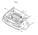
- Fig. 1 is a perspective view showing an engine compartment of a motor vehicle.
- Fig. 2 is a top view showing a structure for mounting an air cleaner.
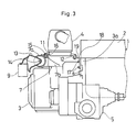
- Fig. 3 is a front view showing the same.
- Fig. 4 is an exploded perspective view showing how the structure for mounting a mounting bracket is attached.
- Embodiments of the present invention will be explained below with reference to the accompanying drawings.
- In Figs. 1 through 3,
reference numeral 1 designates a power plant comprising anengine 2 and atransmission 3. Theengine 2 is arranged such that in the engine compartment, a crank shaft parallels the vehicle bumper (a horizontal direction in Fig. 2).Reference numeral 4 designates an air cleaner which is arranged in a space adjacent to a transverse sides of theengine 2 and above thetransmission 3.Reference numeral 5 designates a differential gear housing connected to thetransmission 3. Thetransmission 3 has a flange 3a on its one end connected to theengine 2 along one of the transverse sides of theengine 2 by a bolt 6 and an upper end part on the other side connected to aframe member 9 of a vehicle body through afirst bracket 7. Thisframe member 9 extends in a longitudinal direction of the vehicle (a vertical direction in Fig. 2) and forms one part of the side wall of the engine compartment. - Referring to Fig. 4, the
first bracket 7 comprises acylindrical member 7a and a supportingmember 7b having a U-shaped longitudinal section which is connected to thecylindrical member 7a and extends from thecylindrical member 7a toward the engine. Thecylindrical member 7a comprises an externalcylindrical member 71, an internalcylindrical member 72 provided in the externalcylindrical member 71 so as to be concentric with the externalcylindrical member 71 and acylindrical rubber member 73 intervening between the twocylindrical members second bracket 13 having a U-shaped cross section is fixed in theframe member 9. Thecylindrical member 7a of thefirst bracket 7 is supported on thesecond bracket 13 by a connectingshaft 14 inserted into the internalcylindrical member 72. In addition, the supportingmember 7b of thefirst bracket 7 is connected to the upper surface of thetransmission 3 by bolt. - The
air cleaner 4 comprises a hot wire type air flow meter. In addition, as shown in Figs. 2 and 3, leftflanges 11 project from the lower left of the air cleaner andright flanges 12 project from the lower right of the air cleaner. - A left supporting
bracket 15 extending in a longitudinal direction of the vehicle body is welded to the supportingmember 7b of thefirst bracket 7 as shown in Fig. 4. More specifically, theleft support bracket 15 has apart 15a extending in a vertical direction and a side end of thispart 15a is welded to the supportingmember 7b. Theleft flanges 11 are mounted on the upper surface of the left supportingbracket 15 by bolts through a rubberelastic mounting member 16. More specifically, theair cleaner 4 is mounted to thetransmission 3 by theflanges 11 through the left supportingbracket 15 and themounting bracket 7. - Referring to Figs. 2 and 3, a right supporting
bracket 18 is mounted on theengine 2. Thebracket 18 is connected to theengine 2 by insertion of bolts 17 through the flange 3a of thetransmission 3. Theright flanges 12 are mounted on the upper surface of the right supportingbracket 18 by bolts through arubber mounting member 19. More specifically, theair cleaner 4 is mounted on theengine 2 by theflanges 12 through the right supportingbracket 18. - Therefore, in the aforementioned structure for mounting the
air cleaner 4, the vibration of theengine 2 is transferred to theair cleaner 4 through the right supportingbracket 18 while the motor vehicle is running. Also, the vibration of thetransmission 3 is transferred to theair cleaner 4 through the left supportingbracket 15 and thefirst bracket 7. Since the vibration of theengine 2 and the vibration of thetransmission 3 have different vibration frequency characteristics, the frequency of the applied vibration force does not coincide with the natural frequency of theair cleaner 4 with the result that resonance of theair cleaner 4 is prevented and the reliability of theair cleaner 4 is improved. - The
power plant 1 generates power plant bending (bending vibration). Theair cleaner 4 is supported on the center section of thepower plant 1 through the right supportingbracket 18 and supported on the end part of thepower plant 1 through the left supportingbracket 15. Therefore, even when the power plant bending is generated, the air cleaner is prevented from receiving the vibration of thepower plant 1 and resonating because the vibration input to theair cleaner 4 through both supportingbrackets - Since the
air cleaner 4 does not resonate in this way, the hot wire is prevented from breaking. As a result, it is possible to accurately measure a quantity of intake air by the air flow meter and normally control theengine 2. - In addition, since the
air cleaner 4 is connected to theengine 2 and thetransmission 3, the distance between supporting points of theair cleaner 4 is less than that required when theair cleaner 4 is connected to theengine 2 and theframe member 9, with the result that the air cleaner can be more stably mounted. Furthermore, since theair cleaner 4 is positioned on thetransmission 3 and the distance between the supporting points is short, it is possible to reduce the height of the hood by effectively using a limited space in the engine compartment. - The present invention is not limited to the structure in the aforementioned embodiment. Although the air cleaner is support at two places in the above embodiment, it may be supported on the power plant or the vehicle body at another place in addition to these two places in order to increase mounting stability.
Claims (12)
first mounting means for mounting the air cleaner to the engine; and
second mounting means for additionally mounting the air cleaner to the transmission.
first bracket means for connecting said frame member means to said second mounting means;
second bracket means for connecting said frame member mounting means to the vehicle body; and
bracket connecting means for connecting said first bracket means to said second bracket means.
said support member means is U-shaped and is mounted to said first bracket means and said cylindrical member means comprises and external cylinder, a concentric internal cylinder and rubber means separating said external cylinder and said internal cylinder and is connected to said second bracket means.
an engine, said engine having a crank shaft, said crank shaft being mounted parallel to the front bumper of the automobile;
a transmission connected to said engine along one of the transverse sides of said engine;
an air cleaner mounted to both said engine and said transmission;
first mounting means for mounting said air cleaner to said engine; and
second mounting means for mounting said air cleaner to said transmission;
said air cleaner being mounted such that it is located adjacent to said transverse side of said engine and above said transmission.
first bracket means for connecting said frame member means to said second mounting means;
second bracket means for connecting said frame member mounting means to the vehicle body: and
bracket connecting means for connecting said first bracket means to said second bracket means.
Applications Claiming Priority (4)
| Application Number | Priority Date | Filing Date | Title |
|---|---|---|---|
| JP10120288 | 1988-07-29 | ||
| JP101202/88U | 1988-07-29 | ||
| JP67187/89U | 1989-06-07 | ||
| JP6718789U JPH0755313Y2 (en) | 1988-07-29 | 1989-06-07 | Engine air cleaner mounting structure |
Publications (2)
| Publication Number | Publication Date |
|---|---|
| EP0352760A1 true EP0352760A1 (en) | 1990-01-31 |
| EP0352760B1 EP0352760B1 (en) | 1993-03-31 |
Family
ID=26408363
Family Applications (1)
| Application Number | Title | Priority Date | Filing Date |
|---|---|---|---|
| EP19890113739 Expired - Lifetime EP0352760B1 (en) | 1988-07-29 | 1989-07-25 | Structure for mounting air cleaner of engine |
Country Status (3)
| Country | Link |
|---|---|
| EP (1) | EP0352760B1 (en) |
| JP (1) | JPH0755313Y2 (en) |
| DE (1) | DE68905700T2 (en) |
Cited By (4)
| Publication number | Priority date | Publication date | Assignee | Title |
|---|---|---|---|---|
| EP0787613A2 (en) * | 1996-01-31 | 1997-08-06 | Suzuki Motor Corporation | Air intake device for internal combustion engine |
| GB2312655A (en) * | 1996-04-30 | 1997-11-05 | Suzuki Motor Co | Support structure for vehicular air cleaner |
| EP1060932A3 (en) * | 1999-06-17 | 2003-01-02 | Volkswagen Aktiengesellschaft | Propulsive power unit with vibration mass damper |
| DE19803230B4 (en) * | 1997-01-31 | 2008-07-17 | Suzuki Motor Corp., Hamamatsu | Intake mounting system for an internal combustion engine |
Families Citing this family (2)
| Publication number | Priority date | Publication date | Assignee | Title |
|---|---|---|---|---|
| JP3362626B2 (en) * | 1997-01-31 | 2003-01-07 | スズキ株式会社 | Engine intake system |
| JP4529177B2 (en) * | 2005-02-28 | 2010-08-25 | スズキ株式会社 | Engine intake system structure |
Citations (5)
| Publication number | Priority date | Publication date | Assignee | Title |
|---|---|---|---|---|
| DE2138950A1 (en) * | 1971-08-04 | 1973-02-15 | Daimler Benz Ag | AIR FILTER SYSTEM FOR COMBUSTION MACHINERY IN VEHICLES |
| US3802169A (en) * | 1971-03-02 | 1974-04-09 | Farr Co | Air filter assembly |
| US4354458A (en) * | 1979-09-14 | 1982-10-19 | David Brown Tractors, Ltd. | Tractor engine air supply means |
| US4533012A (en) * | 1983-04-15 | 1985-08-06 | Toyota Jidosha Kabushiki Kaisha | Intake device of an internal combustion engine |
| US4685531A (en) * | 1986-03-31 | 1987-08-11 | General Motors Corporation | Motor vehicle power train torque strut |
-
1989
- 1989-06-07 JP JP6718789U patent/JPH0755313Y2/en not_active Expired - Fee Related
- 1989-07-25 DE DE1989605700 patent/DE68905700T2/en not_active Expired - Fee Related
- 1989-07-25 EP EP19890113739 patent/EP0352760B1/en not_active Expired - Lifetime
Patent Citations (5)
| Publication number | Priority date | Publication date | Assignee | Title |
|---|---|---|---|---|
| US3802169A (en) * | 1971-03-02 | 1974-04-09 | Farr Co | Air filter assembly |
| DE2138950A1 (en) * | 1971-08-04 | 1973-02-15 | Daimler Benz Ag | AIR FILTER SYSTEM FOR COMBUSTION MACHINERY IN VEHICLES |
| US4354458A (en) * | 1979-09-14 | 1982-10-19 | David Brown Tractors, Ltd. | Tractor engine air supply means |
| US4533012A (en) * | 1983-04-15 | 1985-08-06 | Toyota Jidosha Kabushiki Kaisha | Intake device of an internal combustion engine |
| US4685531A (en) * | 1986-03-31 | 1987-08-11 | General Motors Corporation | Motor vehicle power train torque strut |
Cited By (7)
| Publication number | Priority date | Publication date | Assignee | Title |
|---|---|---|---|---|
| EP0787613A2 (en) * | 1996-01-31 | 1997-08-06 | Suzuki Motor Corporation | Air intake device for internal combustion engine |
| EP0787613A3 (en) * | 1996-01-31 | 1998-12-09 | Suzuki Motor Corporation | Air intake device for internal combustion engine |
| GB2312655A (en) * | 1996-04-30 | 1997-11-05 | Suzuki Motor Co | Support structure for vehicular air cleaner |
| GB2312655B (en) * | 1996-04-30 | 1998-06-10 | Suzuki Motor Co | Support structure for vehicular air cleaner |
| CN1085158C (en) * | 1996-04-30 | 2002-05-22 | 铃木株式会社 | Support for vehicle air filter |
| DE19803230B4 (en) * | 1997-01-31 | 2008-07-17 | Suzuki Motor Corp., Hamamatsu | Intake mounting system for an internal combustion engine |
| EP1060932A3 (en) * | 1999-06-17 | 2003-01-02 | Volkswagen Aktiengesellschaft | Propulsive power unit with vibration mass damper |
Also Published As
| Publication number | Publication date |
|---|---|
| JPH038649U (en) | 1991-01-28 |
| DE68905700T2 (en) | 1993-09-02 |
| EP0352760B1 (en) | 1993-03-31 |
| JPH0755313Y2 (en) | 1995-12-20 |
| DE68905700D1 (en) | 1993-05-06 |
Similar Documents
| Publication | Publication Date | Title |
|---|---|---|
| EP0131835B1 (en) | In-tank fuel feed pump supporting device | |
| JP3698293B2 (en) | Rotating device support structure and fuel supply device using the same | |
| US4559776A (en) | Catalytic converter mounting structure for engines | |
| JP2000274485A (en) | Power plant mount for automobile | |
| EP0352760B1 (en) | Structure for mounting air cleaner of engine | |
| US5062496A (en) | Structure for mounting air cleaner of engine | |
| JPH0639903B2 (en) | Engine generator | |
| JP3084997B2 (en) | Automotive engine mounting device | |
| GB2312655A (en) | Support structure for vehicular air cleaner | |
| JP3464113B2 (en) | Automotive engine intake system | |
| US4744411A (en) | Mounting arrangement of an intercooler | |
| JPH074356Y2 (en) | Anti-vibration device for vehicle engine | |
| JP2002120753A (en) | Body structure assembly of automobile having fixing means for apparatus | |
| KR20050026858A (en) | Air cleaner supporting structure in a v-type engine | |
| CN220199010U (en) | Compressor fixed knot constructs and vehicle | |
| JP3591563B2 (en) | Engine intake system structure | |
| JP2605818B2 (en) | Mounting device for radiators | |
| JP3324361B2 (en) | Intake device for internal combustion engine | |
| JPS643812Y2 (en) | ||
| JPH10274122A (en) | Fuel tank storage type fuel pump | |
| JPH0419368B2 (en) | ||
| JPS63154475A (en) | Mount structure of air cleaner | |
| CN112752915A (en) | Vehicle with a steering wheel | |
| JPH0579402A (en) | Engine emission assembly | |
| JPH03267527A (en) | Structure of accessary mounting device of engine |
Legal Events
| Date | Code | Title | Description |
|---|---|---|---|
| PUAI | Public reference made under article 153(3) epc to a published international application that has entered the european phase |
Free format text: ORIGINAL CODE: 0009012 |
|
| AK | Designated contracting states |
Kind code of ref document: A1 Designated state(s): DE FR GB |
|
| RIN1 | Information on inventor provided before grant (corrected) |
Inventor name: TSUCHIDA, TSUYOSHI Inventor name: KONDOH, KOICHI Inventor name: FUKUDA, HIROTAKA |
|
| 17P | Request for examination filed |
Effective date: 19900621 |
|
| 17Q | First examination report despatched |
Effective date: 19911017 |
|
| GRAA | (expected) grant |
Free format text: ORIGINAL CODE: 0009210 |
|
| AK | Designated contracting states |
Kind code of ref document: B1 Designated state(s): DE FR GB |
|
| REF | Corresponds to: |
Ref document number: 68905700 Country of ref document: DE Date of ref document: 19930506 |
|
| ET | Fr: translation filed | ||
| PLBE | No opposition filed within time limit |
Free format text: ORIGINAL CODE: 0009261 |
|
| STAA | Information on the status of an ep patent application or granted ep patent |
Free format text: STATUS: NO OPPOSITION FILED WITHIN TIME LIMIT |
|
| 26N | No opposition filed | ||
| PGFP | Annual fee paid to national office [announced via postgrant information from national office to epo] |
Ref country code: FR Payment date: 20010712 Year of fee payment: 13 |
|
| PGFP | Annual fee paid to national office [announced via postgrant information from national office to epo] |
Ref country code: GB Payment date: 20010725 Year of fee payment: 13 |
|
| REG | Reference to a national code |
Ref country code: GB Ref legal event code: IF02 |
|
| PG25 | Lapsed in a contracting state [announced via postgrant information from national office to epo] |
Ref country code: GB Free format text: LAPSE BECAUSE OF NON-PAYMENT OF DUE FEES Effective date: 20020725 |
|
| GBPC | Gb: european patent ceased through non-payment of renewal fee |
Effective date: 20020725 |
|
| PG25 | Lapsed in a contracting state [announced via postgrant information from national office to epo] |
Ref country code: FR Free format text: LAPSE BECAUSE OF NON-PAYMENT OF DUE FEES Effective date: 20030331 |
|
| REG | Reference to a national code |
Ref country code: FR Ref legal event code: ST |
|
| PGFP | Annual fee paid to national office [announced via postgrant information from national office to epo] |
Ref country code: DE Payment date: 20060720 Year of fee payment: 18 |
|
| PG25 | Lapsed in a contracting state [announced via postgrant information from national office to epo] |
Ref country code: DE Free format text: LAPSE BECAUSE OF NON-PAYMENT OF DUE FEES Effective date: 20080201 |