EP0351654A2 - Procédé de transformation de coordonnées à haute précision pour des applications de contrôle du trafic aérien - Google Patents
Procédé de transformation de coordonnées à haute précision pour des applications de contrôle du trafic aérien Download PDFInfo
- Publication number
- EP0351654A2 EP0351654A2 EP89112326A EP89112326A EP0351654A2 EP 0351654 A2 EP0351654 A2 EP 0351654A2 EP 89112326 A EP89112326 A EP 89112326A EP 89112326 A EP89112326 A EP 89112326A EP 0351654 A2 EP0351654 A2 EP 0351654A2
- Authority
- EP
- European Patent Office
- Prior art keywords
- aircraft
- radar
- latitude
- calculating
- conformal
- Prior art date
- Legal status (The legal status is an assumption and is not a legal conclusion. Google has not performed a legal analysis and makes no representation as to the accuracy of the status listed.)
- Granted
Links
Images


Classifications
-
- G—PHYSICS
- G01—MEASURING; TESTING
- G01S—RADIO DIRECTION-FINDING; RADIO NAVIGATION; DETERMINING DISTANCE OR VELOCITY BY USE OF RADIO WAVES; LOCATING OR PRESENCE-DETECTING BY USE OF THE REFLECTION OR RERADIATION OF RADIO WAVES; ANALOGOUS ARRANGEMENTS USING OTHER WAVES
- G01S13/00—Systems using the reflection or reradiation of radio waves, e.g. radar systems; Analogous systems using reflection or reradiation of waves whose nature or wavelength is irrelevant or unspecified
- G01S13/88—Radar or analogous systems specially adapted for specific applications
- G01S13/91—Radar or analogous systems specially adapted for specific applications for traffic control
-
- G—PHYSICS
- G01—MEASURING; TESTING
- G01S—RADIO DIRECTION-FINDING; RADIO NAVIGATION; DETERMINING DISTANCE OR VELOCITY BY USE OF RADIO WAVES; LOCATING OR PRESENCE-DETECTING BY USE OF THE REFLECTION OR RERADIATION OF RADIO WAVES; ANALOGOUS ARRANGEMENTS USING OTHER WAVES
- G01S7/00—Details of systems according to groups G01S13/00, G01S15/00, G01S17/00
- G01S7/02—Details of systems according to groups G01S13/00, G01S15/00, G01S17/00 of systems according to group G01S13/00
- G01S7/28—Details of pulse systems
- G01S7/285—Receivers
- G01S7/295—Means for transforming co-ordinates or for evaluating data, e.g. using computers
- G01S7/2955—Means for determining the position of the radar coordinate system for evaluating the position data of the target in another coordinate system
Definitions
- the invention relates to an improved data processing method or system for accurate coordinate conversion for air traffic control applications.
- Air traffic control is the process of using radar and other electronic detection techniques to locate and track aircraft flying through the airspace, to monitor assigned positions, coordinate courses to prevent intersection collisions and near-misses, and to advise on course corrections to avoid collisions, adverse weather conditions, and for other reasons.
- an air traffic control system includes a plurality of radar sites at diverse geographic locations, which monitor the air traffic and report detected positions of the aircraft to a centralized data processing system for the preparation of an integrated display to an air traffic controller who is a person who can make observations, judgements and recommendations concerning the airplanes identified and displayed at a display station.
- Each radar station can measure the slant range which is the radius vector distance between the radar station and the aircraft, and the azimuth, which is the angle which a vertical plane makes with the Earth, containing the aircraft, the radar station and the center of the Earth, with respect to true north.
- the aircraft is typically required to transmit its measured altitude above the surface of the Earth, this usually being done by a barometric pressure sensing device on board the aircraft, which is coupled with a transponder, which transmits the measured altitude of the aircraft to the radar station or other receiving station in the air traffic control system.
- This data is then processed and integrated with aircraft detection data from other radar stations at a central data processing site for display on a display screen to the air traffic controller.
- Air traffic control systems include a controller at a ground-based monitoring station watching a cathode ray tube display of the radar reflection which depicts the course and speed of an aircraft being monitored. An expert controller watching this display can advise the pilot whether the aircraft is on a collision course with other aircraft or is deviating from an assigned flight path.
- a human controller in the loop" to apply human judgement and backup support in the surveillance and control of air traffic. This requires the display of the air traffic on a suitable flat screen display.
- Cartography addresses the problem of representing the surface of the Earth on a planar surface.
- the Earth does not have a perfectly spherical shape, but instead, because it spins about its polar axis, the Earth is an oblate ellipsoid, that is, an ellipse of rotation with an axis through the minor diameter of the ellipse.
- the equatorial radius along the major diameter of the oblate ellipsoid is 3,443.9 nautical miles
- the polar radius along the minor diameter of the oblate ellipsoid is 3,432.4 nautical miles.
- This difference of 11.5 nautical miles between the equatorial radius and the polar radius of the oblate ellipsoidal Earth is normally assumed to be negligible in cartography for the purposes of air traffic control transformations of aircraft positions into a planar display surface.
- the Earth's shape is that of a perfect sphere with a radius having an intermediate value between the equatorial radius and the polar radius for the oblate ellipsoid.
- the North American Datum of 1983 has an equatorial radius of 3,443.918 nautical miles and a polar radius of 3,432.372 nautical miles and provides a mean radius which is one-third of the quantity of the sum of the polar radius plus twice the equatorial radius of 3,440.069 nautical miles.
- a spherical surface has been assumed with a radius, for example, equal to the mean radius of the oblate ellipsoid.
- Cartographers perform a chart projection for representing all or part of the surface of the ellipsoid upon a planar surface.
- Cartographers have found that the problem of representing the surface of the ellipsoid on a plane surface is that the ellipsoidal surface is undevelopable, that is, no part of it can be flattened without distortion.
- cartographers transfer points from the surface of the ellipsoid onto a plane or other developable surface which can be flattened to form a plane, such as a cylinder or a cone.
- Chart projections are usually classified as to the type of developable surface onto which the spherical or ellipsoidal surface is transferred.
- the primary types are cylindrical projections, conical projections, and azimuthal projections.
- An important property of a map projection for the purposes of air traffic control is to maintain correct angular relationships.
- a projection with this characteristic is said to be conformal.
- the Mercator Projection is a conic projection upon a plane, the cylinder being tangent along the equator.
- the Mercator projection has the desirable property of being a conformal projection since expansion is the same in all directions, and angles are thus correctly shown.
- Another conformal projection is the Lambert Conformal Projection, which is a simple conic projection, where the cone intersects the Earth at two standard parallels, and the spacing of the parallels is altered so that the distortion is the same along them as along the meridians.
- the Lambert Conformal Projection thus maintains angles in the transformation and is widely used for navigation. In azimuthal projections, points on the Earth are projected directly on to a planar surface.
- a stereographic projection is an azimuthal projection where points on the surface of the Earth are projected geometrically onto a tangent plane, from a point on the surface of the Earth opposite of the point of tangency.
- the stereographic projection is a conformal transformation where all angles are uniformly maintained during the transformation. The scale of the stereographic projection increases with distance from the point of tangency, but more slowly than in the gnomonic projection, and an entire hemisphere can be shown without excessive distortion.
- the transformation of aircraft position information from multiple radar stations into a common coordinate system was first discussed by D. Goldenberg and E. W. Wolf, in their above referenced paper.
- a version of the method suggested by Goldenberg and Wolf is currently employed by the Federal Avaiation Aministration of the United States of America, for air traffic control applications in the FAA National Air Space system (NAS) and is described in the FAA Document "Multiple Radar Data Processing," NAS-MD-320, January 1, 1984.
- the NAS method consists of two stages. In the first stage, a single radar station's observations of an aircraft target, are converted into a local stereographic plane, having a point of tangency with an assumed spherical Earth at the location of the radar station.
- Fig. 1 presents the present air traffic control National Air Space system (NAS) coordinate conversion processing method in schematic form.
- Fig. 1 shows the system of a plurality of radar stations which observe aircraft and have the aircraft measurement data reduced to a common coordinate system.
- a plurality of N radar stations are at locations separated by from a few nautical miles to hundreds of nautical miles.
- Observations is an example of a simple case where a first radar station 21 is observing aircraft A, and a second radar station 22 is observing aircraft B.
- the resulting measurement data are slant range and azimuthal angular offset from the radar local north direction and the aircraft altitude, as reported by the aircraft itself.
- Fig. 1 labeled "Geometric Approximation”
- Fig. 1 represents a geometric approximation which is employed to project the images of the aircraft onto local two-dimensional planar surfaces, each of which is tangent to the Earth's assumed spherical surface at the respective radar sites.
- This is represented in the third column of Fig. 1, labeled "Local Stereographic Planes.”
- the respective radar sites shown in the third column on Fig. 1 represent the stereographic mappings of the respective target images. These two associated planes are the "local" stereographic planes.
- the image of aircraft A is projected onto the local radar 21's local stereographic plane 31 and the image of the aircraft B is projected onto the second radar 22's local stereographic plane 32, respectively.
- the final step in the present NAS method is represented in the fourth column, entitled “Truncated Taylor Series Approximation of Transformation,” wherein the method transforms the location of the aircraft in the N plurality of local stereographic planes 31 and 32, into a single plane coordinate system 40 as represented in the far right column in Fig. 1.
- the transformation into the system plane 40 is also a stereographic transformation.
- the system plane is used for air traffic control display purposes and for processing of subsequent functions such as automic heading computations for collision alarm, for example.
- a computer method for accurately transforming multiple radar observations of aircraft into a common coordinate system for air traffic control applications.
- the method involves a transformation from radar observables of the target slant range, azimuth and altitude, to the target position coordinates in a stereographic system plane for display.
- the method includes a conformal coordinate conversion process from geodetic to conformal spherical coordinates followed by a conformal stereographic projection process onto a system display plane. The resulting display of aircraft position on the system plane is more accurate than has been available in the prior art.
- the invention is employed in an air traffic control system, including a plurality of radar stations, located on the surface of the Earth, operatively connected to a data processing system, for displaying the location of targets detected by the radar stations.
- the method includes the step of receiving the slant range, azimuth and altitude measurements of a target at a first one of the radar stations, computing the geodetic latitude and longitude of the target in an ellipsoidal reference system, computing the conformal latitude and longitude of the target in a conformal spherical reference system, and projecting the conformal latitude and longitude of the target from the conformal spherical reference system to a system plane by means of a stereographic projection. In this manner, target positions are depicted accurately and all angles are preserved.
- a transformation must be made from the geodetic system of coordinates, which are referenced with respect to an ellipsoid, to a conformal sphere system of coordinates.
- a conformal sphere is a sphere which has the property that all angles are preserved in the transformation. This means that a heading for a target which is referenced with respect to a north-south position, for example, on the geodetic ellipsoidal surface, will also have the same angular heading with respect to the north-south position on the conformal spherical surface.
- This transformation is made by computing, the conformal latitude of the subtarget point, i.e., the geodetic latitude of the target.
- the value for the longitude of a target expressed in the ellipsoidal system will be the same as the numerical value when expressed in a concentric spherical system.
- a projection After having converted the geodetic latitude of the target to the conformal sphere latitude for the target, a projection must be made onto a planar surface which will, once again, preserve all angles. This is done by a stereographic projection, onto a plane having a point of tangency selected at some location on the surface of the conformal sphere. All points on the conformal surface, which have been depicted by conformal latitude and longitude, are projected onto the tangent plane by means of a ray which emanates from a point on the diametric opposite side of the conformal sphere from the point of tangency for the plane.
- This tangent plane is referred to as the system plane, and is the plane for display of the target locations with their headings preserved.
- the theoretical limit of accuracy for the invention is .00008 nautical miles.
- the shape of the Earth is that of an oblate ellipsoid.
- a plane tangent to any point of the surface of the Earth has a normal which passing through the point of tangency does not necessarily pass through the center of the Earth.
- values of longitude for a position on the surface of the Earth do not vary in magnitude between a geocentric approximation for a spherical surface for the Earth and a geodetic longitude for an ellipsoidal Earth
- the geocentric latitude for a spherical representation of the Earth does have a different value from the true geodetic latitude.
- the geodetic latitude is the angle which the normal to the ellipsoid at a station makes with the plane of the geodetic equator, in an ellipsoidal representation of the Earth.
- Geodetic longitude is the angle between the plane of the geodetic meridian at a station and the plane of the geodetic meridian at Greenwich, for an ellipsoidal representation of the Earth.
- the geocentric latitude is the angle at the center of the ellipsoid used to represent the Earth, between the plane of its Equator and a straight line radius vector to a point on the surface of the ellipsoid.
- the geodetic latitude is an ellipsoid rather than a sphere, and the meridians are ellipses. Since the parallels of latitude are considered to be circles, the geodetic longitude is geocentric, and a separate expression is not required. The difference between the geocentric and the geodetic latitudes has a maximum of about 11.6 minutes at a latitude of 45 o . Because of the oblate ellipsoidal shape of the Earth, the length of a degree of geodetic latitude is not everywhere the same, increasing from about 59.7 nautical miles at the Equator, to about 60.3 nautical miles at the poles.
- Fig. 2 is a schematic diagram of the method of the invention. Multiple radar observations of aircraft are converted to a single coordinate system in a new transformation technique.
- Observations a plurality of N radar stations sense aircraft in the air traffic control system. At the bottom of this column is an example of a radar station 21 observing aircraft A and a radar station 22 observing aircraft B.
- Nearly Exact Geometric Calculation the first eleven steps of the method as shown in Fig. 3, are carried out.
- the method is carried out in a data processing system such as is shown in the system diagram of Fig. 4, wherein the system central processing unit CPU 50 performs the method steps depicted in Fig. 3.
- the CPU 50 is a data processor which executes a computer program embodying the flow diagram of Fig. 3. It can accept digital data streams from several radar stations A1, A2, etc., and can perform the method of Fig. 3 to yield the system plane coordinates x and y for many aircraft detected by the radar stations. The output values of x and y from the CPU 50 are then displayed on the flat, cathode ray tube (CRT) display 60 for viewing by the air traffic controller.
- the method of Fig. 3 has its first eleven steps transforming the radar measurements of the aircraft into worldwide geographic (geodetic) latitude and longitude coordinates in an iterative procedure making use of nearly exact geometric construction. A transformed system is indicated in the third column of Fig.
- the transformation from radar observables of the target slant range, azimuth, and altitude, to target position coordinates in the stereographic display system plane requires a coordinate conversion process followed by a stereographic projection process.
- the measured target azimuth is converted to geocentric azimuth (as if the radar's axis were cited along the geocentric vertical), solving for target geocentric latitude and longitude.
- This geocentric latitude and longitude are then converted to geodetic coordinates.
- the geodetic coordinates of the target position are transformed to the conformal sphere.
- the target position from the conformal sphere is projected onto the stereographic display system plane. This iterative technique is necessary because the Earth centered radial distance to the target is initially unknown.
- the method in accordance with the invention takes the target data for detected aircraft, which is measured relative to a fixed radar station's location, and calculates the coordinates for the detected aircraft in a stereographic plane, which is a two-dimensional representation of the original three-dimensional configuration for the aircraft flying above the surface of the Earth.
- the method of the invention is executed in a computer system such as that shown in Fig. 4, as an iterative procedure.
- the iterative steps are steps 2 through step 9, inclusive, in Table II.
- the geocentric coordinates of the aircraft, the geocentric coordinates of the subtarget point, that is, the geodetic latitude of the target, and the geodetic coordinates of the target are calculated.
- the geodetic coordinates of the target and the subtarget point are the same.
- the required output of the iteration which is required to continue the method, namely steps 11 through 13, uses only the geodetic coordinates of the target.
- the geodetic coordinates in the final steps are converted to coordinates on a conformal sphere and then the coordinates on the conformal sphere are transformed to the two-dimensional coordinates of a stereographic plane.
- step 1 the method begins with the assignment of estimates of parameters required in the iterative steps 2 through 9.
- Fig. 5 and Fig. 10 present the geometry to derive the relationships.
- Equation 1 approximates the subtarget radial distance by the subradar radial distance
- Equation 2 approximates the target radial distance by the sum of the subtarget radial distance and the target altitude.
- Equation 3 converts the radar measurements into units that can be operated upon, namely radians.
- step 2A the angular separation is calculated between the line from the Earth's center to the target and from the Earth's center to the radar.
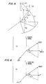
- Figs. 5 and 7 describe the equations in this step. Equation 4 saves computation by calculating the interim value "A" which is used more than once. Equation 5 is the result of the Law of Cosines, used on the triangle in Fig. 7. Equation 6 yields the angle of interest.
- Step 2B provides the elevation angle of the target above the plane tangent to a sphere having a radius equal to the radar radial distance.
- Equation 7 is derived from the Law of Sines applied to the triangle in Fig. 7.
- Equation 8 is the angle of interest calculated from the arcsine of the quantity calculated in Equation 7.
- Step 3 converts the radar azimuth from the geographic coordinate system to the geocentric system. This is necessary in order to get all of the parameters expressed in one coordinate system.
- Fig. 8 and Table III illustrate the coordinate rotation which transforms the azimuth from the radar's coordinate system (that is, the geodetic or geographic) to the geocentric coordinate system. Equations 9, 10 and 11 describe the processing for the special cases where the geodetic azimuth is 90 o , 180 o or 270 o , respectively.
- Steps 3A and 3B calculate the geocentric azimuth in another iterative procedure. Equation 12 approximates the geocentric azimuth by the geodetic azimuth. Equation 13 solves for the geocentric azimuth, more exactly than does Equation 12.
- Step 3C corrects the calcuated geocentric azimuth for ambiguity, which arises since the arctangent of an argument has multiple solutions.
- Step 4 calculates the geocentric latitude of the aircraft because by using relationships of spherical triangles, the geocentric latitude of the aircraft can be calculated. See Fig. 9 and Table IV for a description of this calculation. Equation 14 is the Fortran encoded version of the last equation calculation in Table IV. Equation 15 yields the geocentric latitude of the aircraft by taking the arcsine of the result of Equation 14. Equation 16 calculates the cosine of the target geocentric latitude which is to be used later.
- Step 5A and 5B is used to fine the difference in the longitudes of the radar and of the aircraft, where the direction westward from Greenwich is taken as a positive value.
- Equation 17 assumes the value in the special cases where either the radar or the aircraft are above the true North Pole.
- Equation 18 also comes from Fig. 9. It is derived in the first three Equations in Table IV. The quantity evaluated is the cosine of the longitude difference described above.
- Equation 19 calculates the longitude difference from the result of Equation 18. Equation 20 corrects the result of Equation 19 for multiple solutions.
- Step 6 calculates the difference between the geodetic and the geocentric latitudes of the target. It is depicted in Fig. 10 and in Table V.
- Step 6A initializes the value of the latitude difference by setting it equal to the latitude difference at the radar station. Equation 21 performs that approximation.
- Step 6B is another iterative process to obtain a more accurate value of the latitude difference.
- Equation 22 calculates the value used multiple times. This saves some computation.
- Equation 23 calculates the tangent of the difference of the geocentric latitude and the geodetic latitude of the aircraft.
- Equation 24 calculates the difference by taking the arctangent of the result of equation 23.
- Step 7 calculates the quantity of interest in the main iterative loop, that is the geodetic latitude of the aircraft (and the subtarget point), as can be seen in Fig. 10.
- Step 8 calculates more parameters which will be necessary to obtain a more accurate estimate of the target geodetic latitude in subsequent iterations of steps 2 through 9. See Fig. 10 for these quantities. Equation 26 calculates the difference between the geocentric latitude and the geodetic latitude of the subtarget point. Equation 27 then calculates the geocentric latitude of the subtarget point.
- Step 9 calculates more parameters to be used in subsequent iterations of steps 2 through 9. See Fig. 11. Equation 28 calculates the radial distance to the subtarget point. Equation 29 calculates the radial distance to the target more accurately with each iteration.
- Step 11 has Equation 30 calculate the longitude of the target from the know radar longitude and the longitude difference calculated in Step 5B.
- step 12 and 13 the geodetic latitude and longitude of the target aircraft is established. This information is sufficient for the comparison of all aircraft positions and headings for the entire air traffic control system. However, in order to provide for the display of all target positions and headings on a flat display in a conformal manner, so as to preserve all angles, steps 12 and 13 must be carried out.
- Step 12 now projects the geodetic latitude of the aircraft onto the conformal sphere.
- the property of the conformal projection is that angles measured on the surface of the Earth are preserved on the conformal sphere. Equations 31 and 32 calculate parameters to be used in Equation 33. Equation 33 produces the conformal latitude of the aircraft.
- Step 13 transforms points on the conformal sphere into the two-dimensional stereographic plane for display.
- the inputs are the aircraft conformal latitude, the aircraft longitude, the conformal latitude of the point at which the stereographic plane is tangent to the conformal sphere, the longitude of this point, and the radius of the conformal sphere.
- Equations 34 through 37 produce parameters which are used to calculate the coordinates in the stereographic plane.
- Equation 38 calculates the x coordinate of the aircraft in the stereographic plane
- Equation 39 calculates the y coordinate in the stereographic plane.
- the resulting x and y coordinates are then available for the display with the position and headings, of all of the aircraft in the air traffic control system. Still further, computations can be made on these x and y coordinates to determine closing velocities and other functions.
- the display of the system plane is performed on the system plane display 60 in the system block diagram of Fig. 4.
- the performance of other system plane functions, such as the computation of closing headings, for example, can be performed by the CPU 50 or alternately by the attached data processor 70 shown in Fig. 4.
- Fig. 6 illustrates the relationship between geodetic and geocentric latitude. It is seen that because of the ellipsoidal surface of the Earth, if latitude is defined as the normal to a plane tangent to the surface of the Earth, the geodetic latitude will be different from the geocentric latitude.
- the resulting method provides the display of aircraft altitudes in the stereographic system plane of 10 nautical miles with an accuracy of about 4 to 5 inches.
- the resulting transformation method for air traffic control preserves the inherent accuracy in the input target data sufficient to introduce less than .005 nautical miles of error in target positions in the stereographic display system plane coordinates.
- R2 2 times R (nmi)
- RR R squared (nmi2)
- R r radial distance to the subradar point (nmi)
- H t height of target above the ellipsoidal surface (nmi)
- E p earth polar radius (3432.37166 nmi)
- slcr sine of the geocentric latitude of the subradar point (no units)
- clcr cosine of the geocentric latitude of the subradar point (no units)
- d r deviation from the normal at the subradar point (radians)
- tdr tangent of local deviation from normal at the subradar point (no units)
- cdr cosine of local deviation from normal at the subradar point (no units)
- sdr sine of local deviation from normal at the subradar point (no units)
- KK eccentricity of
- CON the constant ⁇ /2098 for ATCRBS or ⁇ /8192 for Mode-S, used to convert the azimuth change pulse unit of measurement of the radars to radians (radians/azimuth change pulse)
- ⁇ 3.141592654
- ⁇ H .5 times
- ⁇ ⁇ TH 1.5 times
- ⁇ ⁇ TW 2 times ⁇
- This appendix calculates the relation between the radar measured azimuth (that is the azimuth on the plane tangent to the earth at the radar position) and the azimuth on the plane tangent to the sphere with radius equal to the distance from the earth center to the radar (that is, the geocentric radar plane).
- the radar geodetic coordinate system Z is the elevation angle and ⁇ is the azimuth, both measured relative to the radar geodetic horizontal plane.
- z c and ⁇ c are the equivalent quantities in the geocentric system.
- Figure 10 illustrates the configuration of the cross-section of the earth ellipsoid and the target.
- K eccentricity of the earth ellipsoid
- E p ,E q polar and equatorial radii, respectively
- ⁇ ct geocentric latitude of the target
- ⁇ dt geodetic latitude of the target (and therefore the sub-target point)
- ⁇ co geocentric latitude of the sub-target point
- d deviation from the normal at the target (delta in the figures)
- d o deviation from the normal at the sub-target point (delta 'sub o' in the figure)
- T distance from the center of the earth to the target
- R t distance from the center of the earth to the sub-target point
- H t target altitude above the surface of the earth From the law of sines Figure 10
Applications Claiming Priority (2)
| Application Number | Priority Date | Filing Date | Title |
|---|---|---|---|
| US07/222,588 US4899161A (en) | 1988-07-21 | 1988-07-21 | High accuracy coordinate conversion method for air traffic control applications |
| US222588 | 1994-04-04 |
Publications (3)
| Publication Number | Publication Date |
|---|---|
| EP0351654A2 true EP0351654A2 (fr) | 1990-01-24 |
| EP0351654A3 EP0351654A3 (fr) | 1991-04-24 |
| EP0351654B1 EP0351654B1 (fr) | 1994-12-28 |
Family
ID=22832837
Family Applications (1)
| Application Number | Title | Priority Date | Filing Date |
|---|---|---|---|
| EP89112326A Expired - Lifetime EP0351654B1 (fr) | 1988-07-21 | 1989-07-06 | Procédé de transformation de coordonnées à haute précision pour des applications de contrôle du trafic aérien |
Country Status (5)
| Country | Link |
|---|---|
| US (1) | US4899161A (fr) |
| EP (1) | EP0351654B1 (fr) |
| JP (1) | JP2516257B2 (fr) |
| CA (1) | CA1326282C (fr) |
| DE (1) | DE68920218T2 (fr) |
Cited By (7)
| Publication number | Priority date | Publication date | Assignee | Title |
|---|---|---|---|---|
| EP0415587A2 (fr) * | 1989-08-29 | 1991-03-06 | Hughes Aircraft Company | Système de suivi à avertissement précoce |
| GB2292860A (en) * | 1994-09-02 | 1996-03-06 | Caterpillar Inc | Tracking system |
| WO1996015504A2 (fr) * | 1994-11-04 | 1996-05-23 | Lockheed Martin Corporation | Systeme et procede de realisation d'une mosaique de donnees |
| EP0722132A1 (fr) * | 1995-01-16 | 1996-07-17 | SEXTANT AVIONIQUE (Société Anonyme) | Procédé de pilotage d'un aérodyne par asservissement sur une trajectoire horizontale déterminée à partir de points de passage |
| EP1107186A3 (fr) * | 1999-12-03 | 2002-07-24 | FUJI MACHINE Mfg. Co., Ltd. | Système et méthode de traitement d'image |
| EP2202534B1 (fr) * | 2008-12-16 | 2015-02-25 | Thales | Méthode de traîtement de poursuite multi-capteur à temps de latence reduit |
| EP3115803A3 (fr) * | 2015-07-10 | 2017-01-18 | Renesas Electronics Corporation | Dispositif à semi-conducteur, système de commande et procédé d'observation |
Families Citing this family (65)
| Publication number | Priority date | Publication date | Assignee | Title |
|---|---|---|---|---|
| US5440312A (en) * | 1991-06-27 | 1995-08-08 | The Commonwealth Of Australia, The Secretary, Department Of Defence | Auto correlation technique for -co-ordinate registration |
| JP2690422B2 (ja) * | 1991-11-13 | 1997-12-10 | 三菱電機株式会社 | ビデオ表示装置 |
| US5228854A (en) * | 1992-07-21 | 1993-07-20 | Teledyne, Inc. | Combat training system and method |
| US5774826A (en) * | 1995-11-30 | 1998-06-30 | Trimble Navigation Limited | Optimization of survey coordinate transformations |
| US6092022A (en) * | 1997-02-28 | 2000-07-18 | Trimble Navigation | Optimal survey map projection system |
| US6016118A (en) * | 1998-03-05 | 2000-01-18 | Trimble Navigation Limited | Real time integration of a geoid model into surveying activities |
| US6766343B1 (en) * | 2000-02-04 | 2004-07-20 | Harris Corporation | Method and apparatus for coordinate system conversions |
| US8253754B2 (en) * | 2001-01-16 | 2012-08-28 | Microsoft Corporation | Sampling-efficient mapping of images |
| US6683562B2 (en) * | 2001-07-20 | 2004-01-27 | Aviation Communications & Surveillance Systems, Llc | Integrated surveillance display |
| JP2003035553A (ja) * | 2001-07-25 | 2003-02-07 | Nec Corp | 位置情報変換装置及びその方法、位置関連情報提供サーバ並びに位置関連情報提供システム |
| FR2837302A1 (fr) * | 2002-03-13 | 2003-09-19 | Thales Sa | Procede de prediction d'evenements de trafic aerien, notamment pour une aide a la decision des compagnies aeriennes et des aeroports |
| ATE416390T1 (de) * | 2002-07-03 | 2008-12-15 | Ericsson Telefon Ab L M | Verfahren und system zur triangulierung eines objekts |
| FR2913775B1 (fr) * | 2007-03-16 | 2010-08-13 | Thales Sa | Systeme de detection d'obstacle notamment pour un systeme d'anticollision |
| FR2920243B1 (fr) * | 2007-08-21 | 2009-10-30 | Airbus France Sas | Procedes et dispositifs de generation en temps reel de fonds cartographiques |
| JP5627178B2 (ja) * | 2008-12-18 | 2014-11-19 | 三菱電機株式会社 | 状況表示装置 |
| US8321070B2 (en) * | 2009-05-18 | 2012-11-27 | Raytheon Company | Threat object map creation using a three-dimensional sphericity metric |
| US9104695B1 (en) | 2009-07-27 | 2015-08-11 | Palantir Technologies, Inc. | Geotagging structured data |
| US8564596B2 (en) | 2010-01-12 | 2013-10-22 | Palantir Technologies, Inc. | Techniques for density mapping |
| JP5747442B2 (ja) * | 2010-03-18 | 2015-07-15 | 日本電気株式会社 | 追尾装置、追尾方法、及びコンピュータプログラム |
| US9501507B1 (en) | 2012-12-27 | 2016-11-22 | Palantir Technologies Inc. | Geo-temporal indexing and searching |
| JP5565513B1 (ja) * | 2013-01-08 | 2014-08-06 | 日本電気株式会社 | 座標変換装置、座標変換プログラム、座標変換方法 |
| US9123086B1 (en) | 2013-01-31 | 2015-09-01 | Palantir Technologies, Inc. | Automatically generating event objects from images |
| US9092697B2 (en) | 2013-02-07 | 2015-07-28 | Raytheon Company | Image recognition system and method for identifying similarities in different images |
| US8903717B2 (en) | 2013-03-15 | 2014-12-02 | Palantir Technologies Inc. | Method and system for generating a parser and parsing complex data |
| US8855999B1 (en) | 2013-03-15 | 2014-10-07 | Palantir Technologies Inc. | Method and system for generating a parser and parsing complex data |
| US8930897B2 (en) | 2013-03-15 | 2015-01-06 | Palantir Technologies Inc. | Data integration tool |
| US8799799B1 (en) | 2013-05-07 | 2014-08-05 | Palantir Technologies Inc. | Interactive geospatial map |
| US8938686B1 (en) | 2013-10-03 | 2015-01-20 | Palantir Technologies Inc. | Systems and methods for analyzing performance of an entity |
| US10386497B2 (en) * | 2013-10-08 | 2019-08-20 | Javad Gnss, Inc. | Automated localization for GNSS device |
| US8924872B1 (en) | 2013-10-18 | 2014-12-30 | Palantir Technologies Inc. | Overview user interface of emergency call data of a law enforcement agency |
| US9021384B1 (en) | 2013-11-04 | 2015-04-28 | Palantir Technologies Inc. | Interactive vehicle information map |
| US8868537B1 (en) | 2013-11-11 | 2014-10-21 | Palantir Technologies, Inc. | Simple web search |
| US9727376B1 (en) | 2014-03-04 | 2017-08-08 | Palantir Technologies, Inc. | Mobile tasks |
| US9129219B1 (en) | 2014-06-30 | 2015-09-08 | Palantir Technologies, Inc. | Crime risk forecasting |
| US10175348B2 (en) * | 2014-10-08 | 2019-01-08 | Src, Inc. | Use of range-rate measurements in a fusion tracking system via projections |
| US10372879B2 (en) | 2014-12-31 | 2019-08-06 | Palantir Technologies Inc. | Medical claims lead summary report generation |
| EP3070622A1 (fr) | 2015-03-16 | 2016-09-21 | Palantir Technologies, Inc. | Interfaces utilisateur interactives pour réaliser une analyse de données basée sur la localisation |
| US9460175B1 (en) | 2015-06-03 | 2016-10-04 | Palantir Technologies Inc. | Server implemented geographic information system with graphical interface |
| US9600146B2 (en) | 2015-08-17 | 2017-03-21 | Palantir Technologies Inc. | Interactive geospatial map |
| WO2017028203A1 (fr) * | 2015-08-18 | 2017-02-23 | 北京艾肯拓科技有限公司 | Procédé et dispositif pour générer des coordonnées géographiques |
| US10706434B1 (en) | 2015-09-01 | 2020-07-07 | Palantir Technologies Inc. | Methods and systems for determining location information |
| US9639580B1 (en) | 2015-09-04 | 2017-05-02 | Palantir Technologies, Inc. | Computer-implemented systems and methods for data management and visualization |
| US10109094B2 (en) | 2015-12-21 | 2018-10-23 | Palantir Technologies Inc. | Interface to index and display geospatial data |
| US10068199B1 (en) | 2016-05-13 | 2018-09-04 | Palantir Technologies Inc. | System to catalogue tracking data |
| US9686357B1 (en) | 2016-08-02 | 2017-06-20 | Palantir Technologies Inc. | Mapping content delivery |
| US10437840B1 (en) | 2016-08-19 | 2019-10-08 | Palantir Technologies Inc. | Focused probabilistic entity resolution from multiple data sources |
| US10515433B1 (en) | 2016-12-13 | 2019-12-24 | Palantir Technologies Inc. | Zoom-adaptive data granularity to achieve a flexible high-performance interface for a geospatial mapping system |
| US10270727B2 (en) | 2016-12-20 | 2019-04-23 | Palantir Technologies, Inc. | Short message communication within a mobile graphical map |
| US10460602B1 (en) | 2016-12-28 | 2019-10-29 | Palantir Technologies Inc. | Interactive vehicle information mapping system |
| US10579239B1 (en) | 2017-03-23 | 2020-03-03 | Palantir Technologies Inc. | Systems and methods for production and display of dynamically linked slide presentations |
| US10895946B2 (en) | 2017-05-30 | 2021-01-19 | Palantir Technologies Inc. | Systems and methods for using tiled data |
| US11334216B2 (en) | 2017-05-30 | 2022-05-17 | Palantir Technologies Inc. | Systems and methods for visually presenting geospatial information |
| US10403011B1 (en) | 2017-07-18 | 2019-09-03 | Palantir Technologies Inc. | Passing system with an interactive user interface |
| US10371537B1 (en) | 2017-11-29 | 2019-08-06 | Palantir Technologies Inc. | Systems and methods for flexible route planning |
| US11599706B1 (en) | 2017-12-06 | 2023-03-07 | Palantir Technologies Inc. | Systems and methods for providing a view of geospatial information |
| US10698756B1 (en) | 2017-12-15 | 2020-06-30 | Palantir Technologies Inc. | Linking related events for various devices and services in computer log files on a centralized server |
| US10896234B2 (en) | 2018-03-29 | 2021-01-19 | Palantir Technologies Inc. | Interactive geographical map |
| US10830599B2 (en) | 2018-04-03 | 2020-11-10 | Palantir Technologies Inc. | Systems and methods for alternative projections of geographical information |
| US11585672B1 (en) | 2018-04-11 | 2023-02-21 | Palantir Technologies Inc. | Three-dimensional representations of routes |
| US10429197B1 (en) | 2018-05-29 | 2019-10-01 | Palantir Technologies Inc. | Terrain analysis for automatic route determination |
| CN109100698B (zh) * | 2018-09-17 | 2019-08-30 | 中国电子科技集团公司第二十八研究所 | 一种用于海上编队的雷达目标球面投影方法 |
| US10467435B1 (en) | 2018-10-24 | 2019-11-05 | Palantir Technologies Inc. | Approaches for managing restrictions for middleware applications |
| US11025672B2 (en) | 2018-10-25 | 2021-06-01 | Palantir Technologies Inc. | Approaches for securing middleware data access |
| CN112243083B (zh) * | 2019-07-19 | 2022-03-08 | 杭州海康威视数字技术股份有限公司 | 抓拍方法、装置及计算机存储介质 |
| CN117153000B (zh) * | 2023-11-01 | 2024-02-02 | 天宇航空数据科技(合肥)有限责任公司 | 一种基于三维雷达数据的进离场航线影响分析方法及系统 |
Citations (4)
| Publication number | Priority date | Publication date | Assignee | Title |
|---|---|---|---|---|
| US3996590A (en) * | 1961-02-02 | 1976-12-07 | Hammack Calvin M | Method and apparatus for automatically detecting and tracking moving objects and similar applications |
| US4196474A (en) * | 1974-02-11 | 1980-04-01 | The Johns Hopkins University | Information display method and apparatus for air traffic control |
| EP0199380A2 (fr) * | 1985-03-28 | 1986-10-29 | The Boeing Company | Systèmes de navigation pour aéronefs et procédés de génération de points de repère navigationnels |
| US4791572A (en) * | 1985-11-20 | 1988-12-13 | Mets, Inc. | Method for accurately displaying positional information on a map |
Family Cites Families (3)
| Publication number | Priority date | Publication date | Assignee | Title |
|---|---|---|---|---|
| US3623090A (en) * | 1968-11-15 | 1971-11-23 | Butler National Corp | Air traffic control system |
| US3971025A (en) * | 1973-01-02 | 1976-07-20 | International Telephone And Telegraph Corporation | Airport ground surveiliance system with aircraft taxi control feature |
| US4023158A (en) * | 1973-10-15 | 1977-05-10 | International Telephone And Telegraph Corporation | Real three-dimension visual display arrangement |
-
1988
- 1988-07-21 US US07/222,588 patent/US4899161A/en not_active Expired - Lifetime
-
1989
- 1989-07-06 CA CA000604988A patent/CA1326282C/fr not_active Expired - Fee Related
- 1989-07-06 EP EP89112326A patent/EP0351654B1/fr not_active Expired - Lifetime
- 1989-07-06 DE DE68920218T patent/DE68920218T2/de not_active Expired - Fee Related
- 1989-07-19 JP JP1184884A patent/JP2516257B2/ja not_active Expired - Fee Related
Patent Citations (4)
| Publication number | Priority date | Publication date | Assignee | Title |
|---|---|---|---|---|
| US3996590A (en) * | 1961-02-02 | 1976-12-07 | Hammack Calvin M | Method and apparatus for automatically detecting and tracking moving objects and similar applications |
| US4196474A (en) * | 1974-02-11 | 1980-04-01 | The Johns Hopkins University | Information display method and apparatus for air traffic control |
| EP0199380A2 (fr) * | 1985-03-28 | 1986-10-29 | The Boeing Company | Systèmes de navigation pour aéronefs et procédés de génération de points de repère navigationnels |
| US4791572A (en) * | 1985-11-20 | 1988-12-13 | Mets, Inc. | Method for accurately displaying positional information on a map |
Non-Patent Citations (2)
| Title |
|---|
| A.S. LOCKE et al.: "Guidance", 1955, D. Van Nostrand Co., Inc., Princeton, US * |
| MASSACHUSETTS INSTITUTE OF TECHNOLOGY LINCOLN LABORATORY, Technical report no. 67, 13th September 1954, Lexington, MA, US; D. GOLDENBERG et al.: "A common co-ordinate system for the utilization of data from several radars" * |
Cited By (15)
| Publication number | Priority date | Publication date | Assignee | Title |
|---|---|---|---|---|
| EP0415587A3 (en) * | 1989-08-29 | 1992-12-23 | Hughes Aircraft Company | Early warning tracking system |
| EP0415587A2 (fr) * | 1989-08-29 | 1991-03-06 | Hughes Aircraft Company | Système de suivi à avertissement précoce |
| US5587929A (en) * | 1994-09-02 | 1996-12-24 | Caterpillar Inc. | System and method for tracking objects using a detection system |
| GB2292860A (en) * | 1994-09-02 | 1996-03-06 | Caterpillar Inc | Tracking system |
| GB2292860B (en) * | 1994-09-02 | 1997-11-19 | Caterpillar Inc | System and method for tracking objects using a detection system |
| US5668739A (en) * | 1994-09-02 | 1997-09-16 | Caterpillar Inc. | System and method for tracking objects using a detection system |
| WO1996015504A2 (fr) * | 1994-11-04 | 1996-05-23 | Lockheed Martin Corporation | Systeme et procede de realisation d'une mosaique de donnees |
| WO1996015504A3 (fr) * | 1994-11-04 | 1996-08-08 | Unisys Corp | Systeme et procede de realisation d'une mosaique de donnees |
| US5742297A (en) * | 1994-11-04 | 1998-04-21 | Lockheed Martin Corporation | Apparatus and method for constructing a mosaic of data |
| FR2729480A1 (fr) * | 1995-01-16 | 1996-07-19 | Sextant Avionique | Procede de pilotage d'un aerodyne par asservissement sur une trajectoire horizontale determinee a partir de points de passage |
| EP0722132A1 (fr) * | 1995-01-16 | 1996-07-17 | SEXTANT AVIONIQUE (Société Anonyme) | Procédé de pilotage d'un aérodyne par asservissement sur une trajectoire horizontale déterminée à partir de points de passage |
| EP1107186A3 (fr) * | 1999-12-03 | 2002-07-24 | FUJI MACHINE Mfg. Co., Ltd. | Système et méthode de traitement d'image |
| US6661931B1 (en) | 1999-12-03 | 2003-12-09 | Fuji Machine Mfg. Co., Ltd. | Image processing method, image processing system, and modifying-data producing method |
| EP2202534B1 (fr) * | 2008-12-16 | 2015-02-25 | Thales | Méthode de traîtement de poursuite multi-capteur à temps de latence reduit |
| EP3115803A3 (fr) * | 2015-07-10 | 2017-01-18 | Renesas Electronics Corporation | Dispositif à semi-conducteur, système de commande et procédé d'observation |
Also Published As
| Publication number | Publication date |
|---|---|
| JPH02140681A (ja) | 1990-05-30 |
| EP0351654B1 (fr) | 1994-12-28 |
| CA1326282C (fr) | 1994-01-18 |
| JP2516257B2 (ja) | 1996-07-24 |
| US4899161A (en) | 1990-02-06 |
| EP0351654A3 (fr) | 1991-04-24 |
| DE68920218T2 (de) | 1995-06-29 |
| DE68920218D1 (de) | 1995-02-09 |
Similar Documents
| Publication | Publication Date | Title |
|---|---|---|
| EP0351654B1 (fr) | Procédé de transformation de coordonnées à haute précision pour des applications de contrôle du trafic aérien | |
| US6784840B2 (en) | Method for determining azimuth and elevation angles using a single axis direction finding system | |
| US5402116A (en) | Atmospheric pressure calibration systems and methods | |
| EP0427431B1 (fr) | Systèmes de navigation | |
| US4405986A (en) | GSP/Doppler sensor velocity derived attitude reference system | |
| US5867804A (en) | Method and system for the control and management of a three dimensional space envelope | |
| US20040225432A1 (en) | Method and system for the navigation and control of vehicles at an airport and in the surrounding airspace | |
| US6006158A (en) | Airport guidance and safety system incorporating lighting control using GNSS compatible methods | |
| Ostroumov et al. | An airspace analysis according to area navigation requirements | |
| CN108693545A (zh) | 基于星载ads-b的异常目标定位方法 | |
| CN107783157B (zh) | 基于导航卫星的外辐射源智能选星方法、系统及雷达平台 | |
| US4179697A (en) | Passive ranging method | |
| CN115343744A (zh) | 空中运动目标的光学单双星联合星上定位方法及系统 | |
| US5999130A (en) | Determination of radar threat location from an airborne vehicle | |
| Grabbe et al. | Geo-location using direction finding angles | |
| Heymsfield et al. | An interactive system for compositing digital radar and satellite data | |
| JP3539799B2 (ja) | 航空管制用レーダシステム | |
| CN110096721B (zh) | 一种航天器对地面复杂区域目标的观测可见性判断方法 | |
| Shank | A coordinate conversion algorithm for multisensor data processing | |
| RU2711834C1 (ru) | Способ определения орбиты космического аппарата с аппаратурой для съёмки подстилающей поверхности | |
| Acres et al. | Tetrahedra and Relative Directions in Space, Using 2 and 3-Space Simplexes for 3-Space Localization | |
| US20050143872A1 (en) | Aircraft gps instrumentation system and relative method | |
| Kakarlapudi | Application of Image Analysis Techniques in Forward Looking Synthetic Vision System Integrity Monitors | |
| Fischer | Lirncoln Laboratory | |
| Hasler et al. | Four dimensional observations of clouds from geosynchronous orbit using stereo display and measurement techniques on an interactive information processing system |
Legal Events
| Date | Code | Title | Description |
|---|---|---|---|
| PUAI | Public reference made under article 153(3) epc to a published international application that has entered the european phase |
Free format text: ORIGINAL CODE: 0009012 |
|
| AK | Designated contracting states |
Kind code of ref document: A2 Designated state(s): DE FR GB IT NL |
|
| 17P | Request for examination filed |
Effective date: 19900512 |
|
| PUAL | Search report despatched |
Free format text: ORIGINAL CODE: 0009013 |
|
| AK | Designated contracting states |
Kind code of ref document: A3 Designated state(s): DE FR GB IT NL |
|
| 17Q | First examination report despatched |
Effective date: 19930630 |
|
| GRAA | (expected) grant |
Free format text: ORIGINAL CODE: 0009210 |
|
| AK | Designated contracting states |
Kind code of ref document: B1 Designated state(s): DE FR GB IT NL |
|
| PG25 | Lapsed in a contracting state [announced via postgrant information from national office to epo] |
Ref country code: IT Free format text: LAPSE BECAUSE OF FAILURE TO SUBMIT A TRANSLATION OF THE DESCRIPTION OR TO PAY THE FEE WITHIN THE PRE;WARNING: LAPSES OF ITALIAN PATENTS WITH EFFECTIVE DATE BEFORE 2007 MAY HAVE OCCURRED AT ANY TIME BEFORE 2007. THE CORRECT EFFECTIVE DATE MAY BE DIFFERENT FROM THE ONE RECORDED.SCRIBED TIME-LIMIT Effective date: 19941228 Ref country code: NL Effective date: 19941228 |
|
| REF | Corresponds to: |
Ref document number: 68920218 Country of ref document: DE Date of ref document: 19950209 |
|
| ET | Fr: translation filed | ||
| NLV1 | Nl: lapsed or annulled due to failure to fulfill the requirements of art. 29p and 29m of the patents act | ||
| PLBE | No opposition filed within time limit |
Free format text: ORIGINAL CODE: 0009261 |
|
| STAA | Information on the status of an ep patent application or granted ep patent |
Free format text: STATUS: NO OPPOSITION FILED WITHIN TIME LIMIT |
|
| 26N | No opposition filed | ||
| REG | Reference to a national code |
Ref country code: GB Ref legal event code: IF02 |
|
| PGFP | Annual fee paid to national office [announced via postgrant information from national office to epo] |
Ref country code: DE Payment date: 20070831 Year of fee payment: 19 |
|
| PGFP | Annual fee paid to national office [announced via postgrant information from national office to epo] |
Ref country code: GB Payment date: 20070727 Year of fee payment: 19 |
|
| PGFP | Annual fee paid to national office [announced via postgrant information from national office to epo] |
Ref country code: FR Payment date: 20070717 Year of fee payment: 19 |
|
| GBPC | Gb: european patent ceased through non-payment of renewal fee |
Effective date: 20080706 |
|
| PG25 | Lapsed in a contracting state [announced via postgrant information from national office to epo] |
Ref country code: DE Free format text: LAPSE BECAUSE OF NON-PAYMENT OF DUE FEES Effective date: 20090203 |
|
| REG | Reference to a national code |
Ref country code: FR Ref legal event code: ST Effective date: 20090331 |
|
| PG25 | Lapsed in a contracting state [announced via postgrant information from national office to epo] |
Ref country code: GB Free format text: LAPSE BECAUSE OF NON-PAYMENT OF DUE FEES Effective date: 20080706 |
|
| PG25 | Lapsed in a contracting state [announced via postgrant information from national office to epo] |
Ref country code: FR Free format text: LAPSE BECAUSE OF NON-PAYMENT OF DUE FEES Effective date: 20080731 |