EP0351224A2 - Dual-purpose rotating brush for vacuum cleaner - Google Patents
Dual-purpose rotating brush for vacuum cleaner Download PDFInfo
- Publication number
- EP0351224A2 EP0351224A2 EP89307128A EP89307128A EP0351224A2 EP 0351224 A2 EP0351224 A2 EP 0351224A2 EP 89307128 A EP89307128 A EP 89307128A EP 89307128 A EP89307128 A EP 89307128A EP 0351224 A2 EP0351224 A2 EP 0351224A2
- Authority
- EP
- European Patent Office
- Prior art keywords
- brush
- floor tool
- spindle
- bristle
- support wheel
- Prior art date
- Legal status (The legal status is an assumption and is not a legal conclusion. Google has not performed a legal analysis and makes no representation as to the accuracy of the status listed.)
- Withdrawn
Links
Images


Classifications
-
- A—HUMAN NECESSITIES
- A47—FURNITURE; DOMESTIC ARTICLES OR APPLIANCES; COFFEE MILLS; SPICE MILLS; SUCTION CLEANERS IN GENERAL
- A47L—DOMESTIC WASHING OR CLEANING; SUCTION CLEANERS IN GENERAL
- A47L9/00—Details or accessories of suction cleaners, e.g. mechanical means for controlling the suction or for effecting pulsating action; Storing devices specially adapted to suction cleaners or parts thereof; Carrying-vehicles specially adapted for suction cleaners
- A47L9/02—Nozzles
- A47L9/04—Nozzles with driven brushes or agitators
- A47L9/0461—Dust-loosening tools, e.g. agitators, brushes
- A47L9/0466—Rotating tools
- A47L9/0477—Rolls
-
- A—HUMAN NECESSITIES
- A47—FURNITURE; DOMESTIC ARTICLES OR APPLIANCES; COFFEE MILLS; SPICE MILLS; SUCTION CLEANERS IN GENERAL
- A47L—DOMESTIC WASHING OR CLEANING; SUCTION CLEANERS IN GENERAL
- A47L9/00—Details or accessories of suction cleaners, e.g. mechanical means for controlling the suction or for effecting pulsating action; Storing devices specially adapted to suction cleaners or parts thereof; Carrying-vehicles specially adapted for suction cleaners
- A47L9/02—Nozzles
- A47L9/04—Nozzles with driven brushes or agitators
- A47L9/0427—Gearing or transmission means therefor
- A47L9/0444—Gearing or transmission means therefor for conveying motion by endless flexible members, e.g. belts
Definitions
- the present invention relates to housewares and, more particularly, to vacuum cleaners.
- Vacuum cleaners are almost indispensable houseware appliances for household cleaning. Generally, they consist of a fan or blower operative to produce a partial vacuum at an intake. Air sucked in by the partial vacuum passes through a filter bag, whereby dirt particles are removed from the air stream. The filtered air is returned to the environment.
- Pure-vacuum cleaners such as described above, are most suited to removing dust, dirt and hair from hard surfaces such as, for example, wood or tile. Dust, dirt and hair found on a carpet or fabric may adhere so strongly thereto that a vacuum-only cleaner may be incapable of satisfactory cleaning. Vacuum cleaners meet this additional problem with a rotating cylindrical brush contacting the surface being cleaned. The brush tends to dislodge dust, dirt and hair which is thereupon entrained in the air stream created by the partial vacuum. Once moving in the air stream, the dust, dirt and hair is filtered from the air stream by the filter bag.
- Vacuum cleaners are called upon to clean bare surfaces as well as carpeted surfaces.
- the bristles of a rotary brush having a length appropriate for contacting the surface of a carpet are too short to contact a hard surface.
- bristles that are long enough to contact a hard surface conventionally bear too hard upon a carpet.
- the prior art responds to the problem of differing height requirements for hard and carpeted surfaces by providing means for raising and lowering the floor tool of the vacuum cleaner to a selectable height above the surface. Such a provision adds substantially to the cost of the floor tool.
- the invention provides a rotary brush for a vacuum cleaner having first and second types of tufts of bristles.
- the first tufts have a different length and stiffness from the second tufts.
- the lengths of the first tufts are appropriate for cleaning carpets, and those of the second tufts are appropriate for cleaning bare floors.
- the rotary brush has tufts of two different lengths.
- the tufts of longer length appropriate for contacting a bare surface, may be softer and may have fewer strands therein, thereby to avoid catching in the nap of carpets and/or to roll the edges thereof.
- the tufts of shorter length remain substantially out of contact with hard surfaces, but are of appropriate length to contact the nap of carpet.
- Variation in the stiffness of the bristle tufts may be created by varying the diameter of the bristle and/or by varying the number of bristles in a tuft.
- the present invention provides a cylindrical power brush for a vacuum cleaner having two types of bristle tufts.
- One type of bristle tuft is short and stiff for contacting and agitating a carpeted surface.
- the other type of bristle tuft is longer and softer for contacting a hard surface.
- the tufts for the hard surface may contain substantially fewer bristles, whereby catching and rolling of carpet edges is avoided.
- One embodiment alternates types of bristle tufts in a row of bristle tufts.
- Another embodiment employs multiple rows of bristle tufts arranged such that a point on a surface being cleaned is contacted alternately by the two types of bristle tuft.
- Winding up of thread and hair on the axle of the rotating brush is avoided by overlapping annular extensions on a support wheel and a brush spindle.
- the brush support wheel is locked in place in the floor tool by a resilient locking tab integrally formed with one of the halves of the floor tool.
- a rotatable brush for a vacuum cleaner comprising: a brush spindle, at least one row of bristle tufts in the brush spindle, the at least one row extending a substantial axial distance along the brush spindle, the at least one row including first and second types of bristle tufts, the first type of bristle tuft having a first length and a first stiffness, the second type of bristle tuft having a second length and a second stiffness, the first length and the first stiffness being effective for agitating a carpet surface, the second length being greater than the first length and being great enough to contact a hard surface, the second stiffness being less than the first stiffness, the first and second stiffnesses being created by at least first and second bundle diameters in the first and second bristle tufts, respectively, the first bundle diameter being substantially greater than the second bundle diameter, and the first and second types of bristle tufts being disposed in a pattern giving substantial coverage of both types of
- a rotatable brush and support wheel for a floor tool of a vacuum cleaner comprising: a brush spindle, at least one support wheel, means for affixing the at least one support wheel non-rotatably in the floor tool, means in the support wheel for rotatably supporting an end of the brush spindle, an annular extension from the brush spindle extending toward the support wheel, an outer ring on the support wheel extending toward the brush spindle, and the outer ring having an axial length effective for providing a substantial overlap of the annular extension, whereby hair and threads are prevented from winding up in the floor tool.
- a rotatable brush and support wheel for a floor tool of a vacuum cleaner comprising: a brush spindle, at least one support wheel, means for affixing the at least one support wheel non-rotatably in the floor tool, means in the support wheel for rotatably supporting an end of the brush spindle, an annular extension from the brush spindle extending toward the support wheel, the annular extension forming an inner cavity axially centered in an end of the brush spindle, a guide disk axially centered in the at least one support wheel, the guide disk fitting a substantial distance into the central cavity, whereby hair and threads are prevented from winding up in the floor tool.
- a floor tool for a vacuum cleaner comprising: a rotatable brush, the rotatable brush including a brush spindle, first and second support wheels, cooperating means in the first and second support wheels and the brush spindle for rotatably supporting the brush spindle, the first and second support wheels each including a hub extending axially therefrom in a direction opposite to a direction containing the brush spindle, the floor tool including means for supporting the hub against displacement in a first direction, the floor tool further including a resilient locking tab affixed at a first end to the floor tool, a second end of the locking tap being free, the second end being disposed to contact the hub for locking the hub against motion in a second direction opposite to the first direction, and a resilience of the locking tab permitting the second end to be deflected out of locking contact with the hub, whereby the support wheel and the spindle can be installed in and removed from the floor tool.
- the present invention is usable with any type of vacuum cleaner, including externally powered and internally powered types.
- an internally powered, hand held vacuum cleaner, with a power brush attachment thereon is employed to provide a concrete environment for the description of the invention.
- Vacuum cleaner assembly 10 includes a vacuum cleaner 12 and a power brush attachment 14 shown fixed together in their cooperating mated conditions to form a single rigid unit.
- Vacuum cleaner 12 includes a power unit 16 having a body 18 to which a handle 20 is affixed. Handle 20 may contain rechargeable batteries (not shown).
- a power switch 22 is disposed on body 18 in a position making it accessible to a person holding vacuum cleaner 12 by handle 20. Power switch 22 is conveniently a spring-loaded switch normally biased into the OFF condition and urged to the ON position by pressure of the user's thumb or finger. Actuation of power switch 22 operates an internal motor driving a fan (not shown) within body 18.
- a set of louvers 24 about the perimeter of body 18 permit exit of air driven by the internal fan.
- a dust bowl 26 snaps sealingly onto the forward end of body 18 where it is retained by a spring latch 28.
- a filter (not shown) inside dust bowl 26 retains dirt within dust bowl 26 while the air is discharged through louvers 24.
- a motor cover 50 is integrally formed with a brush housing 52.
- Motor cover 50 and brush housing 52 may be made of any convenient material, but are preferably made of a molded plastic material such as, for example, polypropylene.
- a brush opening 54 extends across substantially the entire width of brush housing 52 to reveal a cylindrical brush 56.
- An access door 57 in motor cover 50 provides access for attaching an internal belt (not shown in Fig. 1) and for cleaning a belt drive mechanism, to be more fully detailed hereinafter.
- an electric motor 58 in motor cover 50 includes a motor shaft 60 having a toothed pulley 62 thereon.
- a flexible toothed drive belt 64 passes over toothed pulley 62 and over a toothed band 66 on cylindrical brush 56.
- a shaft 68 passing through a brush spindle 65 of cylindrical brush 56 rotatably supports cylindrical brush 56, whereby cylindrical brush 56 may be concertedly driven by electric motor 58.
- An inner wall 69 between electric motor 58 and flexible toothed drive belt 64 forms a drive belt chamber 71 for isolating dirt and contaminants loosened by power brush attachment 14 from entry into electric motor 58 wherein they may cause damage.
- a belt guide 73 preferably integrally formed on an inside surface of access door 57, is disposed within the run of flexible toothed drive belt 64 between toothed pulley 62 and toothed band 66.
- a curved dirt-stripper portion 75 on belt guide 73 is disposed closely adjacent toothed band 66. Curved dirt-stripper portion 75 has a curvature substantially matching the curvature of toothed band 66.
- the close proximity of curved dirt-stripper portion 75 to toothed band 66 strips larger particles of dirt from toothed band 66 and/or flexible toothed drive belt 64 before they are carried into drive belt chamber 71 wherein they could interfere with free operation of power brush attachment 14.
- Rotation of cylindrical brush 56 in the clockwise direction in Fig. 2 tends to agitate a surface being cleaned and to hurl loosened dirt towards and into air inlet opening 30 as is desired.
- brush spindle 65 of cylindrical brush 56 includes a plurality of brush tufts 70.
- all brush tufts are of substantially the same length and stiffness.
- the distance between brush spindle 65 and the surface to be cleaned depends on the type of surface being cleaned.
- a hard surface 72 supports brush spindle 65 at a greater height than does a carpeted surface 74. If the length of brush tufts 70 is such as to give satisfactory contact with hard surface 72, as shown in brush tuft 70 a to the left of the Figure, then it is conventionally so long that it digs into carpeted surface 74, or rolls the edges (not shown) of carpeted surface 74.
- brush tuft 70 is made short enough to contact carpeted surface 74, as shown in brush tuft 70 b to the right of the Figure, it rotates free of contact on hard surface 72, and thus fails to contribute to cleaning. It is this apparent incompatibility that has forced other manufacturers of vacuum cleaners to the relatively expensive alternative of providing means for raising and lowering brush spindle 65.
- the present invention overcomes this problem.
- long brush tufts 70 a are interspersed with short brush tufts 70 b in one of several patterns to be discussed hereinafter. It has been discovered that far less stiffness is required in brush tufts 70 a to provide satifactory cleaning of hard surface 72 than is required to clean carpeted surface 74. Accordingly, brush tufts 70 a besides being longer than brush tuft 70 b , can be less stiff than brush tuft 70 b without compromising their ability to clean carpeted surface 74. A length and value of stiffness can be found for brush tufts 70 a which provides satisfactory cleaning of hard surface 72 without digging into or rolling the edges of carpeted surface 74. Thus, both brush tuft 70 a and brush tuft 70 can coexist in cylindrical brush 56.
- brush tufts 70 b do not contact hard surface 72, they contribute little, if anything, to cleaning. However, when brush tufts 70 a and brush tufts 70 b are present in an appropriate pattern, hard surface 72 is satisfactorily cleaned by brush tufts 70 a alone. In addition, brush tufts 70 a do contact carpeted surface 74 and, although they do not interfere with carpeted surface 74, they may add additional agitation to that provided by brush tuft 70 b .
- the stiffness of brush tuft 70 varies with the diameter of the bristles and with the number of bristles making up a brush tuft 70.
- Another way of specifying the number of bristles in brush tuft 70 is to recite the diameter of a bundle of bristles used to fabricate brush tuft 70.
- brush tufts 70 a employ bristles of about 0.004 inch (0.1mm) diameter assembled into bundles of about 0.110 inch (2.8mm) diameter
- brush tufts 70 b are about one millimeter shorter than brush tufts 70 a and employ bristles of about 0.006 inch (0.15mm) diameter assembled into bundles of about 0.140 inch (3.5mm) diameter.
- a cylindrical brush 75 includes a single spiral row of brush tufts 76 in which brush tufts 70a alternate with brush tufts 70b.
- a cylindrical brush 78 includes a first spiral row of brush tufts 80 containing only brush tufts 70b and a second spiral row of brush tufts 82 containing only brush tufts 70a. As cylindrical brush 78 is rotated, the brush tufts in each of spiral rows of brush tufts 80 and 82 contact a particular portion of the surface being cleaned in alternating sequence.
- a further pattern is similar to that shown in Fig. 5 except that each spiral row of brush tufts is divided in the center into one half containing brush tuft 70a and the other half containing brush tuft 70b.
- the half of spiral row of brush tufts 80 for example, containing brush tuft 70a is on the same side of cylindrical brush 78 as the half of spiral row of brush tufts 82 containing brush tuft 70b. In this way, a particular portion of a surface being cleaned is contacted in alternating sequence by brush tufts 70a and 70b.
- FIG. 6 an inside view of brush housing 52 is shown looking toward an end 128 thereof. Cylindrical brush 56, and other elements are removed in this view for clarity of illustration. Reference should also be made to Fig. 7 during the following description. It will be understood that a mirror image of the apparatus illustrated and described is disposed in the other end of motor cover 50 but, since the shape and function of such mirror image will be fully understood from the following description, it will not be described.
- First and second retainer arms 130 and 132 integrally molded with end 128, are angled slightly toward each other.
- An upper end of retainer arm 130 terminates in an outwardly angled portion 134.
- an upper end of retainer arm 132 terminates in an outwardly angled portion 136.
- a hairpin-shaped hub guide 138 integrally molded with end 128, terminates in a part-circular hub retainer 140.
- Part-circular hub retainer 140 has a center 142 indicated by a + symbol.
- a part-circular back-up rib 144 disposed outside part-circular hub retainer 140, has its center co-located with center 142. It will be noted that center 142 is located upward beyond the closest approach of retainer arms 13o and 132. Also, retainer arms 130 and 132 extend further outward from end 128 than do outwardly angled portion 134 and 136.
- a flex-rim wheel 146 includes a central disk 148 and a thin, flexible rim 150.
- a plurality of spokes 152 extend diagonally from a perimeter of central disk 148 to retain central disk 148 in a concentric position.
- a small number of spokes preferably three, is combined with a thin cross section in rim 150 in order to provide substantial deformability in rim 150.
- Central disk 148 includes a hub 154 protruding toward end 128 (Fig. 11).
- a ring 156 concentric with hub 154, is disposed at a radius substantially equal to a radius of part-circular back-up rib 144 (Figs. 6 and 7).
- central disk 148 includes a guide disk 158 having a blind hole 160 centered therein.
- a septum 162 spans the diameter of blind hole 160.
- a guide rod 164 passes loosely through an axial bore 166 in brush spindle 65.
- First and second counterbores 168 and 170 in each end of brush spindle 65 (only one end is shown) accommodate a bushing 172.
- An axial bore 174 permits guide rod 164 to pass therethrough and facilitates relative rotation therebetween.
- An end portion 176 of guide rod 164 is sized for insertion into blind hole 160 with a slot 178 fitting onto septum 162.
- a flange 180 on bushing 172 is recessed within counterbore 170 to provide an annular guide recess 182 having a diameter to accept guide disk 158 of flex-rim wheel 146 therein when the elements in Fig. 8 are fitted together in their operational positions.
- a flex-rim wheel 146 is placed on each end of guide rod 164.
- an end portion 176 at each end of guide rod 164 is inserted into its respective blind hole 160.
- the lengths of brush spindle 65 and guide rod 164 are such that this positioning places guide disk 158 of each flex-rim wheel 146 abutting ends of brush spindle 65.
- each guide disk 158 guidingly enters its respective annular guide recess 182.
- the lengths of brush spindle 65 and guide rod 164 are also effective to position both flex-rim wheels 146 at axial locations wherein ring 156 on each is disposed for abutment with inner surfaces of outwardly angled portion 136 and part-circular back-up rib 144.
- Hub 154 on each flex-rim wheel 146 extends between legs of hairpin-shaped hub guide 138.
- Brush spindle 65 is installed by pressing each flex-rim wheel 146 upward until it locks in place with hub 154 resting against part-circular hub retainer 140 with the axis of hub 154 co-located with center 142 (Fig. 6 ).
- An outside diameter of rim 150 is greater than the distance between retainer arms 130 and 132 at their closest approach.
- Rim 150 is deflected resiliently inward as it moves over-center past the point of closest approach and then expands slightly into stable contact with outwardly angled portions 134 and 136.
- a sufficient amount of resilient deformation of rim 150 is maintained in the stable position to prevent rotation of flex-rim wheel 146 during operation of power brush attachment 14.
- Engagement between septum 162 and slot 178 at each end of guide rod 164 retains guide rod 164 in the non-rotating condition.
- rotation is constrained to cylindrical brush 56 with a bushing 172 contacting guide rod 164 near each end of cylindrical brush 56.
- Figs. 6-9 permits objects such as, for example, hair and threads, to become wound about guide rod 164 and interfere with free rotation of brush spindle 65.
- the user In normal use, the user must occasionally remove brush spindle 65 and flex-rim wheels 146 from power brush attachment 14 to clear such objects.
- the present invention prevents objects from becoming wound about guide rod 164, and thus eliminates the problem.
- a wheel 184 is shown installed on an end of a brush spindle 186.
- An annular extension 188 on brush spindle 186 extends a substantial distance toward wheel 184.
- An outer ring 190 extends toward brush spindle 186, overlapping annular extension 188.
- Annular extension 188 forms an inner cavity 192 in the end of brush spindle 186.
- a guide disk 194, centered in wheel 184 extends a substantial distance into inner cavity 192.
- the remaining components in Fig. 10 have functions similar to those in the prior embodiment and thus do not require description.
- outer ring 190 overlaps annular extension 188 and that annular extension 188, in turn, overlaps guide disk 194. As a consequence, it is difficult, or impossible, for string, hair, and the like, to enter and become wound upon guide rod 164.
- Inner shroud 198 whose other functions are not of concern to the present disclosure, is disposed within a lower floor tool wall 200.
- Inner shroud 198 includes at least one support shelf 202 supporting wheel 184 from below.
- Support shelf 202 supports a lower perimeter of hub 154.
- a vertical member 204 on inner shroud 198 contacts an end of hub 154 to limit the transverse outward position of wheel 184.
- a second support shelf 206 may be provided for supporting outer ring 190, either in addition to, or in place of, support shelf 202.
- An upper floor tool wall 208 mated to lower floor tool wall at a joint 209 includes a resilient locking tab 210 extending at an angle therefrom into locking contact with an upper surface of hub 154.
- a wheel 184 is placed on each end of brush spindle 186. Wheels 184 are urged downward in the figure, whereby hubs 154 bear against the inclined surfaces of their respective resilient locking tabs 210. Resilient locking tabs 210 are thereby deflected outward until the tops of hubs 154 pass. Then, resilient locking tabs 210 snap inward to their locking positions.
- resilient locking tab 210 in its locking position shown, resilient locking tab 210 is in an unstressed condition. As a consequence, the tendency of resin to take a set in a stressed position does not occur. In addition, retention of wheel 184 does not rely on resilient urging from an external or internal member. Thus, reliable, long-term retention is provided by the technique shown and described.
Landscapes
- Engineering & Computer Science (AREA)
- Mechanical Engineering (AREA)
- Nozzles For Electric Vacuum Cleaners (AREA)
Abstract
Description
- The present invention relates to housewares and, more particularly, to vacuum cleaners.
- Vacuum cleaners are almost indispensable houseware appliances for household cleaning. Generally, they consist of a fan or blower operative to produce a partial vacuum at an intake. Air sucked in by the partial vacuum passes through a filter bag, whereby dirt particles are removed from the air stream. The filtered air is returned to the environment.
- Pure-vacuum cleaners, such as described above, are most suited to removing dust, dirt and hair from hard surfaces such as, for example, wood or tile. Dust, dirt and hair found on a carpet or fabric may adhere so strongly thereto that a vacuum-only cleaner may be incapable of satisfactory cleaning. Vacuum cleaners meet this additional problem with a rotating cylindrical brush contacting the surface being cleaned. The brush tends to dislodge dust, dirt and hair which is thereupon entrained in the air stream created by the partial vacuum. Once moving in the air stream, the dust, dirt and hair is filtered from the air stream by the filter bag.
- Vacuum cleaners are called upon to clean bare surfaces as well as carpeted surfaces. The bristles of a rotary brush having a length appropriate for contacting the surface of a carpet are too short to contact a hard surface. Conversely, bristles that are long enough to contact a hard surface conventionally bear too hard upon a carpet.
- The prior art responds to the problem of differing height requirements for hard and carpeted surfaces by providing means for raising and lowering the floor tool of the vacuum cleaner to a selectable height above the surface. Such a provision adds substantially to the cost of the floor tool.
- Accordingly, it is an object of the invention to provide a rotary brush for a vacuum cleaner which overcomes or at least mitigates drawbacks of the prior art.
- It is a further object of the invention to provide a rotary brush for a vacuum cleaner including means for loosening soil on bare floors and on carpets.
- The invention provides a rotary brush for a vacuum cleaner having first and second types of tufts of bristles. The first tufts have a different length and stiffness from the second tufts. The lengths of the first tufts are appropriate for cleaning carpets, and those of the second tufts are appropriate for cleaning bare floors.
- The rotary brush has tufts of two different lengths. The tufts of longer length, appropriate for contacting a bare surface, may be softer and may have fewer strands therein, thereby to avoid catching in the nap of carpets and/or to roll the edges thereof. The tufts of shorter length remain substantially out of contact with hard surfaces, but are of appropriate length to contact the nap of carpet.
- Variation in the stiffness of the bristle tufts may be created by varying the diameter of the bristle and/or by varying the number of bristles in a tuft.
- Briefly stated, the present invention provides a cylindrical power brush for a vacuum cleaner having two types of bristle tufts. One type of bristle tuft is short and stiff for contacting and agitating a carpeted surface. The other type of bristle tuft is longer and softer for contacting a hard surface. In addition to the differences in length and bristle stiffness, the tufts for the hard surface may contain substantially fewer bristles, whereby catching and rolling of carpet edges is avoided. One embodiment alternates types of bristle tufts in a row of bristle tufts. Another embodiment employs multiple rows of bristle tufts arranged such that a point on a surface being cleaned is contacted alternately by the two types of bristle tuft. Winding up of thread and hair on the axle of the rotating brush is avoided by overlapping annular extensions on a support wheel and a brush spindle. The brush support wheel is locked in place in the floor tool by a resilient locking tab integrally formed with one of the halves of the floor tool.
- According to an embodiment of the invention, there is provided a rotatable brush for a vacuum cleaner comprising: a brush spindle, at least one row of bristle tufts in the brush spindle, the at least one row extending a substantial axial distance along the brush spindle, the at least one row including first and second types of bristle tufts, the first type of bristle tuft having a first length and a first stiffness, the second type of bristle tuft having a second length and a second stiffness, the first length and the first stiffness being effective for agitating a carpet surface, the second length being greater than the first length and being great enough to contact a hard surface, the second stiffness being less than the first stiffness, the first and second stiffnesses being created by at least first and second bundle diameters in the first and second bristle tufts, respectively, the first bundle diameter being substantially greater than the second bundle diameter, and the first and second types of bristle tufts being disposed in a pattern giving substantial coverage of both types of bristle tufts over a point on a surface.
- According to a feature of the invention, there is provided a rotatable brush and support wheel for a floor tool of a vacuum cleaner comprising: a brush spindle, at least one support wheel, means for affixing the at least one support wheel non-rotatably in the floor tool, means in the support wheel for rotatably supporting an end of the brush spindle, an annular extension from the brush spindle extending toward the support wheel, an outer ring on the support wheel extending toward the brush spindle, and the outer ring having an axial length effective for providing a substantial overlap of the annular extension, whereby hair and threads are prevented from winding up in the floor tool.
- According to a further feature of the invention, there is provided a rotatable brush and support wheel for a floor tool of a vacuum cleaner comprising: a brush spindle, at least one support wheel, means for affixing the at least one support wheel non-rotatably in the floor tool, means in the support wheel for rotatably supporting an end of the brush spindle, an annular extension from the brush spindle extending toward the support wheel, the annular extension forming an inner cavity axially centered in an end of the brush spindle, a guide disk axially centered in the at least one support wheel, the guide disk fitting a substantial distance into the central cavity, whereby hair and threads are prevented from winding up in the floor tool.
- According to a still further feature of the invention, there is provided a floor tool for a vacuum cleaner comprising: a rotatable brush, the rotatable brush including a brush spindle, first and second support wheels, cooperating means in the first and second support wheels and the brush spindle for rotatably supporting the brush spindle, the first and second support wheels each including a hub extending axially therefrom in a direction opposite to a direction containing the brush spindle, the floor tool including means for supporting the hub against displacement in a first direction, the floor tool further including a resilient locking tab affixed at a first end to the floor tool, a second end of the locking tap being free, the second end being disposed to contact the hub for locking the hub against motion in a second direction opposite to the first direction, and a resilience of the locking tab permitting the second end to be deflected out of locking contact with the hub, whereby the support wheel and the spindle can be installed in and removed from the floor tool.
- The above, and other objects, features and advantages of the present invention will become apparent from the following description read in conjunction with the accompanying drawings, in which like reference numerals designate the same elements.
-
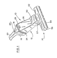
- Fig. 1 is a perspective view of a vacuum cleaner system having a floor tool according to an embodiment of the invention.
- Fig. 2 is a partial cross section of the floor tool of Fig. 1.
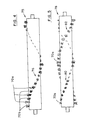
- Fig. 3 is a close-up view of a rotatable brush showing two different types of bristle tufts adapted for bare surfaces and carpeted surfaces.
- Fig. 4 is a front view of a cylindrical brush for a vacuum cleaner showing one pattern for installing the two types of bristle tufts.
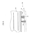
- Fig. 5 is a front view of a cylindrical brush showing a second pattern for installing two types of bristle tufts.
- Fig. 6 is a cross section inside a floor tool showing an end wall thereof.
- Fig. 7 is an exploded partial cross section taken along VII-VII in Fig. 6.
- Fig. 8 is a cross section taken along VIII-VIII in Fig. 7.
- Fig. 9 is a cross section corresponding to Fig. 6 with a flex-rim wheel installed.
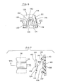
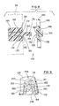
- Fig. 10 is a closeup cross section of an end of a brush spindle mated to a wheel according to an embodiment of the invention.
- Fig. 11 is a closeup view of the brush spindle and wheel of Fig. 10 installed in a floor tool.
- The present invention is usable with any type of vacuum cleaner, including externally powered and internally powered types. For purposes of description, however, an internally powered, hand held vacuum cleaner, with a power brush attachment thereon, is employed to provide a concrete environment for the description of the invention.
- Referring to Fig. 1, there is shown, generally at 10, a vacuum cleaner assembly within which a rotatable brush according to an embodiment of the inventon may be used.
Vacuum cleaner assembly 10 includes avacuum cleaner 12 and apower brush attachment 14 shown fixed together in their cooperating mated conditions to form a single rigid unit.Vacuum cleaner 12 includes apower unit 16 having abody 18 to which ahandle 20 is affixed.Handle 20 may contain rechargeable batteries (not shown). Apower switch 22 is disposed onbody 18 in a position making it accessible to a person holdingvacuum cleaner 12 byhandle 20.Power switch 22 is conveniently a spring-loaded switch normally biased into the OFF condition and urged to the ON position by pressure of the user's thumb or finger. Actuation ofpower switch 22 operates an internal motor driving a fan (not shown) withinbody 18. A set oflouvers 24 about the perimeter ofbody 18 permit exit of air driven by the internal fan. - A
dust bowl 26 snaps sealingly onto the forward end ofbody 18 where it is retained by aspring latch 28. A filter (not shown) insidedust bowl 26 retains dirt withindust bowl 26 while the air is discharged throughlouvers 24. - A
motor cover 50 is integrally formed with abrush housing 52.Motor cover 50 andbrush housing 52 may be made of any convenient material, but are preferably made of a molded plastic material such as, for example, polypropylene. Abrush opening 54 extends across substantially the entire width ofbrush housing 52 to reveal acylindrical brush 56. Anaccess door 57 inmotor cover 50 provides access for attaching an internal belt (not shown in Fig. 1) and for cleaning a belt drive mechanism, to be more fully detailed hereinafter. - Referring now to Fig. 2, an
electric motor 58 inmotor cover 50 includes amotor shaft 60 having atoothed pulley 62 thereon. A flexibletoothed drive belt 64 passes overtoothed pulley 62 and over atoothed band 66 oncylindrical brush 56. Ashaft 68 passing through abrush spindle 65 ofcylindrical brush 56 rotatably supportscylindrical brush 56, wherebycylindrical brush 56 may be concertedly driven byelectric motor 58. Aninner wall 69 betweenelectric motor 58 and flexibletoothed drive belt 64 forms adrive belt chamber 71 for isolating dirt and contaminants loosened bypower brush attachment 14 from entry intoelectric motor 58 wherein they may cause damage. Abelt guide 73, preferably integrally formed on an inside surface ofaccess door 57, is disposed within the run of flexibletoothed drive belt 64 betweentoothed pulley 62 andtoothed band 66. A curved dirt-stripper portion 75 onbelt guide 73 is disposed closely adjacenttoothed band 66. Curved dirt-stripper portion 75 has a curvature substantially matching the curvature oftoothed band 66. The close proximity of curved dirt-stripper portion 75 totoothed band 66 strips larger particles of dirt fromtoothed band 66 and/or flexibletoothed drive belt 64 before they are carried intodrive belt chamber 71 wherein they could interfere with free operation ofpower brush attachment 14. Whenaccess door 57 is removed,belt guide 73, removed with it, clearsdrive belt chamber 71 to enable cleaning of dirt fromdrive belt chamber 71 or reeving of flexibletoothed drive belt 64 ontomotor shaft 60. - Rotation of
cylindrical brush 56 in the clockwise direction in Fig. 2 tends to agitate a surface being cleaned and to hurl loosened dirt towards and into air inlet opening 30 as is desired. - Referring now to Fig. 3,
brush spindle 65 ofcylindrical brush 56 includes a plurality ofbrush tufts 70. In a conventional rotatable brush, all brush tufts are of substantially the same length and stiffness. The distance betweenbrush spindle 65 and the surface to be cleaned depends on the type of surface being cleaned. Ahard surface 72 supportsbrush spindle 65 at a greater height than does a carpetedsurface 74. If the length ofbrush tufts 70 is such as to give satisfactory contact withhard surface 72, as shown inbrush tuft 70a to the left of the Figure, then it is conventionally so long that it digs into carpetedsurface 74, or rolls the edges (not shown) of carpetedsurface 74. Conversely, ifbrush tuft 70 is made short enough to contact carpetedsurface 74, as shown inbrush tuft 70b to the right of the Figure, it rotates free of contact onhard surface 72, and thus fails to contribute to cleaning. It is this apparent incompatibility that has forced other manufacturers of vacuum cleaners to the relatively expensive alternative of providing means for raising and loweringbrush spindle 65. The present invention overcomes this problem. - In the present invention,
long brush tufts 70a are interspersed withshort brush tufts 70b in one of several patterns to be discussed hereinafter. It has been discovered that far less stiffness is required inbrush tufts 70a to provide satifactory cleaning ofhard surface 72 than is required to clean carpetedsurface 74. Accordingly,brush tufts 70a besides being longer thanbrush tuft 70b, can be less stiff thanbrush tuft 70b without compromising their ability to clean carpetedsurface 74. A length and value of stiffness can be found forbrush tufts 70a which provides satisfactory cleaning ofhard surface 72 without digging into or rolling the edges ofcarpeted surface 74. Thus, bothbrush tuft 70a andbrush tuft 70 can coexist incylindrical brush 56. - One skilled in the art will recognize, however, that, since
brush tufts 70b do not contacthard surface 72, they contribute little, if anything, to cleaning. However, whenbrush tufts 70a andbrush tufts 70b are present in an appropriate pattern,hard surface 72 is satisfactorily cleaned bybrush tufts 70a alone. In addition,brush tufts 70a do contact carpetedsurface 74 and, although they do not interfere withcarpeted surface 74, they may add additional agitation to that provided bybrush tuft 70b. - For a given type of material in bristles of
brush tufts 70, the stiffness ofbrush tuft 70 varies with the diameter of the bristles and with the number of bristles making up abrush tuft 70. Another way of specifying the number of bristles inbrush tuft 70 is to recite the diameter of a bundle of bristles used to fabricatebrush tuft 70. - In one satisfactory embodiment,
brush tufts 70a employ bristles of about 0.004 inch (0.1mm) diameter assembled into bundles of about 0.110 inch (2.8mm) diameter, andbrush tufts 70b are about one millimeter shorter thanbrush tufts 70a and employ bristles of about 0.006 inch (0.15mm) diameter assembled into bundles of about 0.140 inch (3.5mm) diameter. - Several patterns of
brush tufts brush tufts cylindrical brush 75 includes a single spiral row ofbrush tufts 76 in whichbrush tufts 70a alternate withbrush tufts 70b. Although it is recognized that the different types of brush tufts contact a surface side by side, and not in the same track, spreading of the bristles in each brush tuft as it contacts a surface tends to cause sufficient overlap for adequate cleaning. - Referring now to Fig. 5, a
cylindrical brush 78 includes a first spiral row ofbrush tufts 80 containing only brushtufts 70b and a second spiral row ofbrush tufts 82 containing only brushtufts 70a. Ascylindrical brush 78 is rotated, the brush tufts in each of spiral rows ofbrush tufts - A further pattern is similar to that shown in Fig. 5 except that each spiral row of brush tufts is divided in the center into one half containing
brush tuft 70a and the other half containingbrush tuft 70b. The half of spiral row ofbrush tufts 80, for example, containingbrush tuft 70a is on the same side ofcylindrical brush 78 as the half of spiral row ofbrush tufts 82 containingbrush tuft 70b. In this way, a particular portion of a surface being cleaned is contacted in alternating sequence bybrush tufts - Other patterns would occur to one skilled in the art without departing from the spirit and scope of the present invention.
- For purposes of orienting the reader, the following brief resume is given of a brush-mounting technique fully disclosed in U.S. Patent Application Serial No. 929,103, the disclosure of which is herein incorporated by reference.
- Referring now to Fig. 6, an inside view of
brush housing 52 is shown looking toward anend 128 thereof.Cylindrical brush 56, and other elements are removed in this view for clarity of illustration. Reference should also be made to Fig. 7 during the following description. It will be understood that a mirror image of the apparatus illustrated and described is disposed in the other end ofmotor cover 50 but, since the shape and function of such mirror image will be fully understood from the following description, it will not be described. - First and
second retainer arms end 128, are angled slightly toward each other. An upper end ofretainer arm 130 terminates in an outwardlyangled portion 134. Similarly, an upper end ofretainer arm 132 terminates in an outwardlyangled portion 136. A hairpin-shapedhub guide 138, integrally molded withend 128, terminates in a part-circular hub retainer 140. Part-circular hub retainer 140 has acenter 142 indicated by a + symbol. A part-circular back-uprib 144, disposed outside part-circular hub retainer 140, has its center co-located withcenter 142. It will be noted thatcenter 142 is located upward beyond the closest approach ofretainer arms 13o and 132. Also,retainer arms end 128 than do outwardlyangled portion - Referring now also to Figs. 8 and 9, a flex-
rim wheel 146 includes acentral disk 148 and a thin,flexible rim 150. A plurality of spokes 152 (best seen in Fig. 9) extend diagonally from a perimeter ofcentral disk 148 to retaincentral disk 148 in a concentric position. Preferably, a small number of spokes, preferably three, is combined with a thin cross section inrim 150 in order to provide substantial deformability inrim 150. -
Central disk 148 includes ahub 154 protruding toward end 128 (Fig. 11). Aring 156, concentric withhub 154, is disposed at a radius substantially equal to a radius of part-circular back-up rib 144 (Figs. 6 and 7). At the side opposite to that containinghub 154,central disk 148 includes aguide disk 158 having ablind hole 160 centered therein. Aseptum 162 spans the diameter ofblind hole 160. - Referring specifically now to Fig. 8, a
guide rod 164 passes loosely through anaxial bore 166 inbrush spindle 65. First andsecond counterbores bushing 172. Anaxial bore 174 permits guiderod 164 to pass therethrough and facilitates relative rotation therebetween. Anend portion 176 ofguide rod 164 is sized for insertion intoblind hole 160 with aslot 178 fitting ontoseptum 162. Aflange 180 onbushing 172 is recessed withincounterbore 170 to provide anannular guide recess 182 having a diameter to acceptguide disk 158 of flex-rim wheel 146 therein when the elements in Fig. 8 are fitted together in their operational positions. - Referring as necessary to Figs. 6-9, to install
cylindrical brush 56 inbrush housing 52, a flex-rim wheel 146 is placed on each end ofguide rod 164. In this condition, anend portion 176 at each end ofguide rod 164 is inserted into its respectiveblind hole 160. The lengths ofbrush spindle 65 and guiderod 164 are such that this positioning placesguide disk 158 of each flex-rim wheel 146 abutting ends ofbrush spindle 65. In one embodiment, in the described condition, eachguide disk 158 guidingly enters its respectiveannular guide recess 182. - The lengths of
brush spindle 65 and guiderod 164 are also effective to position both flex-rim wheels 146 at axial locations whereinring 156 on each is disposed for abutment with inner surfaces of outwardlyangled portion 136 and part-circular back-uprib 144.Hub 154 on each flex-rim wheel 146 extends between legs of hairpin-shapedhub guide 138.Brush spindle 65 is installed by pressing each flex-rim wheel 146 upward until it locks in place withhub 154 resting against part-circular hub retainer 140 with the axis ofhub 154 co-located with center 142 (Fig. 6 ). An outside diameter ofrim 150 is greater than the distance betweenretainer arms Rim 150 is deflected resiliently inward as it moves over-center past the point of closest approach and then expands slightly into stable contact with outwardlyangled portions spokes 152, and their diagonal orientation, contributes to the required resiliency ofrim 150. A sufficient amount of resilient deformation ofrim 150 is maintained in the stable position to prevent rotation of flex-rim wheel 146 during operation ofpower brush attachment 14. Engagement betweenseptum 162 and slot 178 at each end ofguide rod 164 retainsguide rod 164 in the non-rotating condition. Thus, rotation is constrained tocylindrical brush 56 with abushing 172 contactingguide rod 164 near each end ofcylindrical brush 56. - It was discovered that the construction of Figs. 6-9 permits objects such as, for example, hair and threads, to become wound about
guide rod 164 and interfere with free rotation ofbrush spindle 65. In normal use, the user must occasionally removebrush spindle 65 and flex-rim wheels 146 frompower brush attachment 14 to clear such objects. The present invention prevents objects from becoming wound aboutguide rod 164, and thus eliminates the problem. - Referring now to Fig. 10, a
wheel 184 is shown installed on an end of abrush spindle 186. Anannular extension 188 onbrush spindle 186 extends a substantial distance towardwheel 184. Anouter ring 190 extends towardbrush spindle 186, overlappingannular extension 188.Annular extension 188 forms aninner cavity 192 in the end ofbrush spindle 186. Aguide disk 194, centered inwheel 184 extends a substantial distance intoinner cavity 192. The remaining components in Fig. 10 have functions similar to those in the prior embodiment and thus do not require description. - It will be noted that
outer ring 190 overlapsannular extension 188 and thatannular extension 188, in turn, overlaps guidedisk 194. As a consequence, it is difficult, or impossible, for string, hair, and the like, to enter and become wound uponguide rod 164. - The embodiment in Figs. 6-9, corresponding to the disclosure of the referenced patent application, suffers another problem. Referring momentarily to Figs. 6-9, it has been found that, over time,
flexible rim 150 and retainingarms flexible rim 150 may not be gripped firmly enough to prevent rotation, or to remain in position holdingcylindrical brush 56 in position. - Referring to Fig. 11, there is shown an improved technique for retaining
brush spindle 186 in position in afloor tool 196. Aninner shroud 198, whose other functions are not of concern to the present disclosure, is disposed within a lowerfloor tool wall 200.Inner shroud 198 includes at least onesupport shelf 202 supportingwheel 184 from below.Support shelf 202, as shown, supports a lower perimeter ofhub 154. ln addition, avertical member 204 oninner shroud 198 contacts an end ofhub 154 to limit the transverse outward position ofwheel 184. Asecond support shelf 206 may be provided for supportingouter ring 190, either in addition to, or in place of,support shelf 202. - An upper
floor tool wall 208 mated to lower floor tool wall at a joint 209 includes aresilient locking tab 210 extending at an angle therefrom into locking contact with an upper surface ofhub 154. - To install
brush spindle 186, awheel 184 is placed on each end ofbrush spindle 186.Wheels 184 are urged downward in the figure, wherebyhubs 154 bear against the inclined surfaces of their respectiveresilient locking tabs 210.Resilient locking tabs 210 are thereby deflected outward until the tops ofhubs 154 pass. Then,resilient locking tabs 210 snap inward to their locking positions. - It is worth noting that, in its locking position shown,
resilient locking tab 210 is in an unstressed condition. As a consequence, the tendency of resin to take a set in a stressed position does not occur. In addition, retention ofwheel 184 does not rely on resilient urging from an external or internal member. Thus, reliable, long-term retention is provided by the technique shown and described. - Having described preferred embodiments of the invention with reference to the accompanying drawings, it is to be understood that the invention is not limited to those precise embodiments, and that various changes and modifications may be effected therein by one skilled in the art without departing from the scope or spirit of the invention as defined in the appended claims.
Claims (15)
a brush spindle;
at least one row of bristle tufts in said brush spindle;
said at least one row extending a substantial axial distance along said brush spindle;
said bristle tufts including first and second types of bristle tufts;
said first type of bristle tuft having a first length and a first stiffness;
said second type of bristle tuft having a second length and a second stiffness;
said first length and said first stiffness being effective for agitating a carpet surface;
said second length being greater than said first length and being great enough to contact a hard surface;
said second stiffness being less than said first stiffness; and
said first and second types of bristle tufts being disposed in a pattern giving substantial coverage of both types of bristle tufts over a point on a surface.
said first and second stiffnesses are created by first and second bristle diameters; and
said first bristle diameter is greater than said second bristle diameter.
said at least one row includes at least first and second rows;
at least a first portion of said first row including only said first type of bristle tuft;
at least a second portion of said second row including only said second type of bristle tuft; and
said first portion and said second portion being disposed along substantially the same axial portion of said spindle, whereby a surface being cleaned is exposed alternately to said first and said second bristle types.
said first row includes only said first type of bristle tuft; and
said second row includes only said second type of bristle tuft.
said first row includes a first half containing only said first type of bristle tuft and a second half containing only said second type of bristle tuft;
said second row includes a third half containing only said second type of bristle tuft and a fourth half containing only said first type of bristle tuft;
said first and third halves being disposed along a fifth half of an axial length of said brush spindle; and
said second and fourth halves being disposed along a sixth half of an axial length of said brush spindle.
a brush spindle:
at least one support wheel;
means for affixing said at least one support wheel non-rotatably in said floor tool;
means in said support wheel for rotatably supporting an end of said brush spindle;
an annular extension from said brush spindle extending toward said support wheel;
an outer ring on said support wheel extending toward said brush spindle; and
said outer ring having an axial length effective for providing a substantial overlap of said annular extension, whereby hair and threads are prevented from winding up in said floor tool.
a brush spindle;
at least one support wheel;
means for affixing said at least one support wheel non-rotatably in said floor tool;
means in said support wheel for rotatably supporting an end of said brush spindle;
an annular extension from said brush spindle extending twoards said support wheel;
said annular extension forming an inner cacity axiallyu centered in an end of said brush spindle;
a guide disk axially centered in said at least one support wheel; and
said guide disk fitting a substantial distance into said central cavity, whereby hair and threads are prevented from winding up in said floor tool.
an outer ring on said support wheel extending towards said brush spindle; and
said outer ring having an axial length effective for providing a substantial overlap of said annular extension, whereby hair and threads are further prevented from winding up in said floor tool.
a rotatable brush;
said rotatable brush including a brush spindle;
first and second support wheels;
cooperating means in said first and second support wheels and said brush spindle for rotatably supporting said brush spindle;
said first and second support wheels each including a hub extending axially therefrom in a direction opposite to a direction containing said brush spindle;
said floor tool including means for supporting said hub against displacement in a first direction;
said floor tool further including a resilient locking tab affixed at a first end to said floor tool;
a second end of said locking tap being free;
said second end being disposed to contact said hub for locking said hub against motion in a second direction opposite to said first direction; and
a resilience of said locking tab permitting said second end to be deflected out of locking contact with said hub, whereby said support wheel and said spindle can be installed in and removed from said floor tool.
said floor tool includes a lower floor tool portion and an upper floor tool portion;
means for mating said lower floor tool portion to said upper floor tool portion;
said means for supporting being disposed in said lower floor tool portion;
said upper floor tool portion including an upper floor tool wall; and
said resilient locking tab being affixed to said upper floor tool wall.
said locking tab includes an inclined portion between said upper floor tool wall and said end; and
said locking tab is deflectable toward said upper floor tool wall for release of said hub.
said inclined portion is deflected by said hub during insertion of said spindle and said support wheel into a position permitting said hub to pass; and
a resilience of said locking tab being effective to permit said end of said locking tab to spring outward said locking position when said hub has moved therepast into its operational position.
Applications Claiming Priority (2)
| Application Number | Priority Date | Filing Date | Title |
|---|---|---|---|
| US218568 | 1988-07-13 | ||
| US07/218,568 US4912805A (en) | 1988-07-13 | 1988-07-13 | Dual-purpose rotating brush for vacuum cleaner |
Publications (2)
| Publication Number | Publication Date |
|---|---|
| EP0351224A2 true EP0351224A2 (en) | 1990-01-17 |
| EP0351224A3 EP0351224A3 (en) | 1991-03-20 |
Family
ID=22815620
Family Applications (1)
| Application Number | Title | Priority Date | Filing Date |
|---|---|---|---|
| EP19890307128 Withdrawn EP0351224A3 (en) | 1988-07-13 | 1989-07-13 | Dual-purpose rotating brush for vacuum cleaner |
Country Status (3)
| Country | Link |
|---|---|
| US (1) | US4912805A (en) |
| EP (1) | EP0351224A3 (en) |
| CA (1) | CA1324465C (en) |
Cited By (10)
| Publication number | Priority date | Publication date | Assignee | Title |
|---|---|---|---|---|
| WO1995028123A1 (en) * | 1994-04-15 | 1995-10-26 | Vorwerk & Co. Interholding Gmbh | Brush cleaning device, especially for carpeting |
| EP0705557A1 (en) * | 1994-10-03 | 1996-04-10 | Tennant Company | Scrubbing machine having offset cylindrical brushes |
| EP0649626A3 (en) * | 1993-10-20 | 1997-08-13 | Windsor Ind Inc | Apparatus for monitoring cleaning element wear. |
| EP1145677A1 (en) * | 2000-04-13 | 2001-10-17 | Wessel-Werk Gmbh | Suction nozzle for vacuum cleaner |
| GB2409405A (en) * | 2003-12-15 | 2005-06-29 | Samsung Kwangju Electronics Co | Suction cleaner brush |
| US9241603B1 (en) | 2014-10-08 | 2016-01-26 | Emerson Electric Co. | Swivel assembly for connecting a wand to a vacuum accessory and associated accessory tool for use on hard surface |
| EP3173002A1 (en) | 2015-11-30 | 2017-05-31 | Black & Decker Inc. | Cleaning head |
| CN107252276A (en) * | 2017-07-07 | 2017-10-17 | 小狗电器互联网科技(北京)股份有限公司 | A kind of round brush and its dust catcher |
| US10258213B2 (en) | 2014-10-08 | 2019-04-16 | Emerson Electric Co. | Balanced airflow for a vacuum accessory |
| US10264937B2 (en) | 2014-10-08 | 2019-04-23 | Emerson Electric Co. | Swivel assembly for a vacuum accessory |
Families Citing this family (44)
| Publication number | Priority date | Publication date | Assignee | Title |
|---|---|---|---|---|
| US5495634A (en) * | 1994-06-30 | 1996-03-05 | Bruns Brush Inc. (Ohio Corporation) | Vacuum sweeper roller brush |
| US5632060A (en) * | 1995-08-04 | 1997-05-27 | Bissell Inc. | Vacuum cleaner with agitation member drive belt access panel |
| US6167587B1 (en) | 1997-07-09 | 2001-01-02 | Bissell Homecare, Inc. | Upright extraction cleaning machine |
| US6286169B1 (en) | 1997-01-27 | 2001-09-11 | Tennant Company | Tessellated cylindrical brush |
| US6438793B1 (en) | 1997-07-09 | 2002-08-27 | Bissell Homecare, Inc. | Upright extraction cleaning machine |
| USRE39304E1 (en) * | 1997-07-09 | 2006-09-26 | Bissell Homecare, Inc. | Upright extraction cleaning machine |
| US6314611B1 (en) | 2000-03-24 | 2001-11-13 | Baker Mcmillen Co. | Bladed disk brush roller assembly for a vacuum cleaner sweeper |
| USD461604S1 (en) | 2001-02-09 | 2002-08-13 | The Toro Company | Housing for a blower/vacuum |
| US6442790B1 (en) | 2001-02-09 | 2002-09-03 | The Toro Company | Portable blower/vacuum having air inlet cover attachable to blower tube |
| US6574823B1 (en) | 2001-02-12 | 2003-06-10 | The Scott Fetzer Company | Brushroll |
| US6591440B2 (en) | 2001-10-10 | 2003-07-15 | The Scott Fetzer Company | Brushroll with rotatably mounted end assembly |
| US6591441B2 (en) | 2001-10-10 | 2003-07-15 | The Scott Fetzer Company | Brushroll having improved cleaning capability |
| US20030145424A1 (en) * | 2002-02-01 | 2003-08-07 | Royal Appliance Mfg. Co. | Two-piece brushroll |
| US6760952B1 (en) | 2003-06-20 | 2004-07-13 | The Scott Fetzer Company | Vacuum cleaner brushroll |
| KR100746935B1 (en) * | 2003-07-09 | 2007-08-08 | 도시바 테크 가부시키가이샤 | Intake vent and electric cleaner |
| US20050039282A1 (en) * | 2003-08-22 | 2005-02-24 | Oreck Holdings, Llc | Vacuum cleaner brushroll |
| US6779231B1 (en) | 2003-09-25 | 2004-08-24 | The Scott Fetzer Company | V-belt driven vacuum cleaner brushroll |
| CA2554972C (en) * | 2004-02-04 | 2010-01-19 | S. C. Johnson & Son, Inc. | Surface treating device with cartridge-based cleaning system |
| US8117714B2 (en) | 2005-03-09 | 2012-02-21 | Bissell Homecare, Inc. | Vacuum cleaner with hair collection element |
| US20080152487A1 (en) * | 2006-12-22 | 2008-06-26 | Shaffer Chadwick A | Portable blower/vacuum and impeller for use with same |
| US9010882B2 (en) | 2011-04-25 | 2015-04-21 | Irobot Corporation | Debris guard for a wheel assembly |
| US9326654B2 (en) * | 2013-03-15 | 2016-05-03 | Irobot Corporation | Roller brush for surface cleaning robots |
| US9693663B2 (en) | 2013-03-15 | 2017-07-04 | Bissell Homecare, Inc. | Tufting method and brushroll for vacuum cleaner |
| GB2514842B (en) * | 2013-06-07 | 2015-09-16 | Techtronic Floor Care Tech Ltd | Agitator assembly |
| CN206995197U (en) * | 2014-03-19 | 2018-02-13 | 尚科宁家运营有限公司 | Floor Treatment Equipment |
| USD747050S1 (en) * | 2014-05-14 | 2016-01-05 | The Toro Company | Housing of a portable blower/vacuum |
| JP6424461B2 (en) * | 2014-05-16 | 2018-11-21 | 富士ゼロックス株式会社 | Cleaning member, charging device, image forming apparatus |
| US9756998B2 (en) | 2014-05-28 | 2017-09-12 | Bissell Homecare, Inc. | Brushroll for vacuum cleaner |
| US11992172B2 (en) | 2018-10-19 | 2024-05-28 | Sharkninja Operating Llc | Agitator for a surface treatment apparatus and a surface treatment apparatus having the same |
| US10602895B2 (en) | 2014-12-12 | 2020-03-31 | Bissell Homecare, Inc. | Brushroll for vacuum cleaner |
| GB2534983B (en) | 2014-12-12 | 2019-10-30 | Bissell Homecare Inc | Brushroll for vacuum cleaner |
| US10702108B2 (en) * | 2015-09-28 | 2020-07-07 | Sharkninja Operating Llc | Surface cleaning head for vacuum cleaner |
| US11647881B2 (en) | 2015-10-21 | 2023-05-16 | Sharkninja Operating Llc | Cleaning apparatus with combing unit for removing debris from cleaning roller |
| CN208693165U (en) | 2015-10-21 | 2019-04-05 | 尚科宁家运营有限公司 | Surface cleaning head with dual rotary agitators |
| CN105982625B (en) * | 2016-04-14 | 2019-07-09 | 北京小米移动软件有限公司 | Automatic cleaning equipment and its cleaning components |
| US11202542B2 (en) | 2017-05-25 | 2021-12-21 | Sharkninja Operating Llc | Robotic cleaner with dual cleaning rollers |
| US10905297B2 (en) | 2018-01-05 | 2021-02-02 | Irobot Corporation | Cleaning head including cleaning rollers for cleaning robots |
| US11272781B2 (en) * | 2018-04-13 | 2022-03-15 | Kevin W. Rose | Hair collector apparatus and related methods |
| JP7152837B2 (en) | 2018-10-19 | 2022-10-13 | シャークニンジャ オペレーティング エルエルシー | Stirrer for surface treatment equipment and surface treatment equipment having the same |
| CN210383784U (en) * | 2019-01-24 | 2020-04-24 | 北京石头世纪科技股份有限公司 | Robot brush, component and robot |
| US11109727B2 (en) | 2019-02-28 | 2021-09-07 | Irobot Corporation | Cleaning rollers for cleaning robots |
| WO2022089585A1 (en) * | 2020-10-29 | 2022-05-05 | 苏州宝时得电动工具有限公司 | Cleaning apparatus and roller brush thereof |
| US11684227B2 (en) | 2021-06-02 | 2023-06-27 | Bissell Inc. | Surface cleaning apparatus having a brushroll |
| CN117513218B (en) * | 2024-01-05 | 2024-04-26 | 河南誉满鑫环保科技有限公司 | Street cleaning device |
Family Cites Families (14)
| Publication number | Priority date | Publication date | Assignee | Title |
|---|---|---|---|---|
| US1462568A (en) * | 1917-07-26 | 1923-07-24 | Hoover Co | Brush-adjusting device for suction cleaners |
| US1884013A (en) * | 1927-04-20 | 1932-10-25 | North H Losey | Suction cleaner |
| US2459007A (en) * | 1945-04-09 | 1949-01-11 | Westinghouse Electric Corp | Brush roll for suction cleaners |
| US2668979A (en) * | 1949-10-29 | 1954-02-16 | Scott & Fetzer Co | Vacuum cleaner nozzle with detachable brush carrying unit |
| GB1321081A (en) * | 1970-01-21 | 1973-06-20 | Prestige Group Ltd | Carpet sweepers having rotary brushes |
| US3716889A (en) * | 1970-10-12 | 1973-02-20 | Wallace Leisure Prod Inc | Vacuum cleaner |
| US3737937A (en) * | 1971-09-07 | 1973-06-12 | Whirlpool Co | Rotary brush construction for vacuum cleaner |
| DE2153058A1 (en) * | 1971-10-25 | 1973-05-03 | Siemens Elektrogeraete Gmbh | SUCTION CLEANER |
| US3846865A (en) * | 1973-07-13 | 1974-11-12 | Royal Appliance Mfg | Attachment clip for suction cleaner brush |
| US4042997A (en) * | 1976-10-29 | 1977-08-23 | Bissell, Inc. | Vacuum cleaner with improved brush |
| DE2728992A1 (en) * | 1977-06-28 | 1979-01-18 | Duepro Ag | CLEANING DEVICE |
| DE2817197A1 (en) * | 1978-04-20 | 1979-10-31 | Vorwerk Co Interholding | FLOOR CARE UNIT |
| US4361929A (en) * | 1981-03-26 | 1982-12-07 | Black & Decker Inc. | Vacuum cleaner tool having a two-position rotary brush |
| US4662027A (en) * | 1985-10-21 | 1987-05-05 | Parker Winfred C | Brush roller attachment kit |
-
1988
- 1988-07-13 US US07/218,568 patent/US4912805A/en not_active Expired - Fee Related
-
1989
- 1989-06-30 CA CA000604536A patent/CA1324465C/en not_active Expired - Fee Related
- 1989-07-13 EP EP19890307128 patent/EP0351224A3/en not_active Withdrawn
Cited By (14)
| Publication number | Priority date | Publication date | Assignee | Title |
|---|---|---|---|---|
| EP0649626A3 (en) * | 1993-10-20 | 1997-08-13 | Windsor Ind Inc | Apparatus for monitoring cleaning element wear. |
| WO1995028123A1 (en) * | 1994-04-15 | 1995-10-26 | Vorwerk & Co. Interholding Gmbh | Brush cleaning device, especially for carpeting |
| EP0705557A1 (en) * | 1994-10-03 | 1996-04-10 | Tennant Company | Scrubbing machine having offset cylindrical brushes |
| EP1145677A1 (en) * | 2000-04-13 | 2001-10-17 | Wessel-Werk Gmbh | Suction nozzle for vacuum cleaner |
| GB2409405A (en) * | 2003-12-15 | 2005-06-29 | Samsung Kwangju Electronics Co | Suction cleaner brush |
| GB2409405B (en) * | 2003-12-15 | 2005-12-07 | Samsung Kwangju Electronics Co | A dust agitator and vacuum cleaner having the same |
| US9241603B1 (en) | 2014-10-08 | 2016-01-26 | Emerson Electric Co. | Swivel assembly for connecting a wand to a vacuum accessory and associated accessory tool for use on hard surface |
| US9545182B2 (en) | 2014-10-08 | 2017-01-17 | Emerson Electric Co. | Swivel assembly for connecting a wand to a vacuum accessory and associated accessory tool for use on hard surfaces |
| US10258213B2 (en) | 2014-10-08 | 2019-04-16 | Emerson Electric Co. | Balanced airflow for a vacuum accessory |
| US10264937B2 (en) | 2014-10-08 | 2019-04-23 | Emerson Electric Co. | Swivel assembly for a vacuum accessory |
| EP3173002A1 (en) | 2015-11-30 | 2017-05-31 | Black & Decker Inc. | Cleaning head |
| US9844307B2 (en) | 2015-11-30 | 2017-12-19 | Black & Decker Inc. | Cleaning head |
| CN107252276A (en) * | 2017-07-07 | 2017-10-17 | 小狗电器互联网科技(北京)股份有限公司 | A kind of round brush and its dust catcher |
| CN107252276B (en) * | 2017-07-07 | 2019-07-09 | 小狗电器互联网科技(北京)股份有限公司 | A kind of round brush and its dust catcher |
Also Published As
| Publication number | Publication date |
|---|---|
| CA1324465C (en) | 1993-11-23 |
| EP0351224A3 (en) | 1991-03-20 |
| US4912805A (en) | 1990-04-03 |
Similar Documents
| Publication | Publication Date | Title |
|---|---|---|
| US4912805A (en) | Dual-purpose rotating brush for vacuum cleaner | |
| US12207781B2 (en) | Cleaner | |
| KR102807469B1 (en) | A vaccum cleaner | |
| KR102546702B1 (en) | A vaccum cleaner | |
| US4646380A (en) | Rotary cleaning member in cleaner | |
| EP1748719B1 (en) | Tool for a surface treating appliance | |
| US4841594A (en) | Cordless vacuum cleaner with power brush | |
| US9844307B2 (en) | Cleaning head | |
| US5029361A (en) | Floor nozzle for vacuum cleaner | |
| EP4090209B1 (en) | Floor cleaner | |
| EP3646756B1 (en) | A vacuum cleaner | |
| US20080052846A1 (en) | Cleaning robot roller processing | |
| AU2010212337A1 (en) | Vacuum accessory tool | |
| KR20120025525A (en) | A cleaner head | |
| KR20120024779A (en) | A cleaner head | |
| CA3087466C (en) | Brushroll for vacuum cleaner | |
| CA2035954C (en) | Debris impeller | |
| US20020020036A1 (en) | Multi-use floor tool | |
| EP1827193B1 (en) | Agitator for suction nozzle in vacuum cleaner | |
| CA1090959A (en) | Soil-releasing roller for wet or dry carpet-cleaning apparatus | |
| JP4176601B2 (en) | Suction port and vacuum cleaner | |
| JPH09327424A (en) | Rotary sweeping member of vacuum cleaner | |
| JP2023545771A (en) | Stirrer for surface treatment equipment and surface treatment equipment with it | |
| JPH0588467U (en) | Rotating rotor of suction nozzle for vacuum cleaner | |
| TWM681474U (en) | Roller brush, roller brush assembly, cleaning device, and cleaning system |
Legal Events
| Date | Code | Title | Description |
|---|---|---|---|
| PUAI | Public reference made under article 153(3) epc to a published international application that has entered the european phase |
Free format text: ORIGINAL CODE: 0009012 |
|
| AK | Designated contracting states |
Kind code of ref document: A2 Designated state(s): DE FR GB IT |
|
| RHK1 | Main classification (correction) |
Ipc: A47L 9/04 |
|
| PUAL | Search report despatched |
Free format text: ORIGINAL CODE: 0009013 |
|
| AK | Designated contracting states |
Kind code of ref document: A3 Designated state(s): DE FR GB IT |
|
| 17P | Request for examination filed |
Effective date: 19910919 |
|
| STAA | Information on the status of an ep patent application or granted ep patent |
Free format text: STATUS: THE APPLICATION IS DEEMED TO BE WITHDRAWN |
|
| 18D | Application deemed to be withdrawn |
Effective date: 19930202 |