EP0349872A1 - Method and apparatus for the manufacture of hollow bodies from thermoplastics material - Google Patents
Method and apparatus for the manufacture of hollow bodies from thermoplastics material Download PDFInfo
- Publication number
- EP0349872A1 EP0349872A1 EP89111570A EP89111570A EP0349872A1 EP 0349872 A1 EP0349872 A1 EP 0349872A1 EP 89111570 A EP89111570 A EP 89111570A EP 89111570 A EP89111570 A EP 89111570A EP 0349872 A1 EP0349872 A1 EP 0349872A1
- Authority
- EP
- European Patent Office
- Prior art keywords
- laminate
- storage space
- annular piston
- annular
- extrusion
- Prior art date
- Legal status (The legal status is an assumption and is not a legal conclusion. Google has not performed a legal analysis and makes no representation as to the accuracy of the status listed.)
- Granted
Links
Images


Classifications
-
- B—PERFORMING OPERATIONS; TRANSPORTING
- B29—WORKING OF PLASTICS; WORKING OF SUBSTANCES IN A PLASTIC STATE IN GENERAL
- B29C—SHAPING OR JOINING OF PLASTICS; SHAPING OF MATERIAL IN A PLASTIC STATE, NOT OTHERWISE PROVIDED FOR; AFTER-TREATMENT OF THE SHAPED PRODUCTS, e.g. REPAIRING
- B29C48/00—Extrusion moulding, i.e. expressing the moulding material through a die or nozzle which imparts the desired form; Apparatus therefor
- B29C48/03—Extrusion moulding, i.e. expressing the moulding material through a die or nozzle which imparts the desired form; Apparatus therefor characterised by the shape of the extruded material at extrusion
- B29C48/09—Articles with cross-sections having partially or fully enclosed cavities, e.g. pipes or channels
-
- B—PERFORMING OPERATIONS; TRANSPORTING
- B29—WORKING OF PLASTICS; WORKING OF SUBSTANCES IN A PLASTIC STATE IN GENERAL
- B29C—SHAPING OR JOINING OF PLASTICS; SHAPING OF MATERIAL IN A PLASTIC STATE, NOT OTHERWISE PROVIDED FOR; AFTER-TREATMENT OF THE SHAPED PRODUCTS, e.g. REPAIRING
- B29C48/00—Extrusion moulding, i.e. expressing the moulding material through a die or nozzle which imparts the desired form; Apparatus therefor
- B29C48/16—Articles comprising two or more components, e.g. co-extruded layers
- B29C48/18—Articles comprising two or more components, e.g. co-extruded layers the components being layers
- B29C48/21—Articles comprising two or more components, e.g. co-extruded layers the components being layers the layers being joined at their surfaces
-
- B—PERFORMING OPERATIONS; TRANSPORTING
- B29—WORKING OF PLASTICS; WORKING OF SUBSTANCES IN A PLASTIC STATE IN GENERAL
- B29C—SHAPING OR JOINING OF PLASTICS; SHAPING OF MATERIAL IN A PLASTIC STATE, NOT OTHERWISE PROVIDED FOR; AFTER-TREATMENT OF THE SHAPED PRODUCTS, e.g. REPAIRING
- B29C48/00—Extrusion moulding, i.e. expressing the moulding material through a die or nozzle which imparts the desired form; Apparatus therefor
- B29C48/25—Component parts, details or accessories; Auxiliary operations
- B29C48/30—Extrusion nozzles or dies
- B29C48/32—Extrusion nozzles or dies with annular openings, e.g. for forming tubular articles
- B29C48/335—Multiple annular extrusion nozzles in coaxial arrangement, e.g. for making multi-layered tubular articles
- B29C48/337—Multiple annular extrusion nozzles in coaxial arrangement, e.g. for making multi-layered tubular articles the components merging at a common location
- B29C48/338—Multiple annular extrusion nozzles in coaxial arrangement, e.g. for making multi-layered tubular articles the components merging at a common location using a die with concentric parts, e.g. rings, cylinders
-
- B—PERFORMING OPERATIONS; TRANSPORTING
- B29—WORKING OF PLASTICS; WORKING OF SUBSTANCES IN A PLASTIC STATE IN GENERAL
- B29C—SHAPING OR JOINING OF PLASTICS; SHAPING OF MATERIAL IN A PLASTIC STATE, NOT OTHERWISE PROVIDED FOR; AFTER-TREATMENT OF THE SHAPED PRODUCTS, e.g. REPAIRING
- B29C48/00—Extrusion moulding, i.e. expressing the moulding material through a die or nozzle which imparts the desired form; Apparatus therefor
- B29C48/25—Component parts, details or accessories; Auxiliary operations
- B29C48/36—Means for plasticising or homogenising the moulding material or forcing it through the nozzle or die
- B29C48/475—Means for plasticising or homogenising the moulding material or forcing it through the nozzle or die using pistons, accumulators or press rams
- B29C48/48—Two or more rams or pistons
-
- B—PERFORMING OPERATIONS; TRANSPORTING
- B29—WORKING OF PLASTICS; WORKING OF SUBSTANCES IN A PLASTIC STATE IN GENERAL
- B29C—SHAPING OR JOINING OF PLASTICS; SHAPING OF MATERIAL IN A PLASTIC STATE, NOT OTHERWISE PROVIDED FOR; AFTER-TREATMENT OF THE SHAPED PRODUCTS, e.g. REPAIRING
- B29C48/00—Extrusion moulding, i.e. expressing the moulding material through a die or nozzle which imparts the desired form; Apparatus therefor
- B29C48/03—Extrusion moulding, i.e. expressing the moulding material through a die or nozzle which imparts the desired form; Apparatus therefor characterised by the shape of the extruded material at extrusion
- B29C48/09—Articles with cross-sections having partially or fully enclosed cavities, e.g. pipes or channels
- B29C48/10—Articles with cross-sections having partially or fully enclosed cavities, e.g. pipes or channels flexible, e.g. blown foils
-
- B—PERFORMING OPERATIONS; TRANSPORTING
- B29—WORKING OF PLASTICS; WORKING OF SUBSTANCES IN A PLASTIC STATE IN GENERAL
- B29C—SHAPING OR JOINING OF PLASTICS; SHAPING OF MATERIAL IN A PLASTIC STATE, NOT OTHERWISE PROVIDED FOR; AFTER-TREATMENT OF THE SHAPED PRODUCTS, e.g. REPAIRING
- B29C49/00—Blow-moulding, i.e. blowing a preform or parison to a desired shape within a mould; Apparatus therefor
- B29C49/02—Combined blow-moulding and manufacture of the preform or the parison
- B29C49/04—Extrusion blow-moulding
- B29C49/041—Extrusion blow-moulding using an accumulator head
Definitions
- the invention relates to a method and a device for producing hollow bodies made of thermoplastic materials, the wall of which is formed as a laminate, which consists of several interconnected layers of at least two plastics of different properties, by means of extrusion blow molding, firstly tubular preforms, the wall of which has a corresponding number of layers which are produced in batches using an extrusion unit which has at least two extruders and a common extrusion head which is provided with an annular storage space for the laminate, an annular piston for emptying the storage space and an extrusion opening through which the preforms are extruded, with all the material streams entering the extrusion head, from which the individual layers of the laminate are formed, passed through the annular piston and into this in di e cross-sectional shape of a ring are brought.
- the procedure is such that all material flows are already connected to one another within the annular piston to form the end laminate from which the wall of the hollow body is formed, and thereafter the end laminate formed in this way through an annular channel which widens in the shape of a funnel cut in the ring piston flows towards the storage space.
- the annular piston In the area of the annular piston in which the individual layers are connected to form the end laminate, the latter has a thickness, that is to say a radial extension, which is substantially less than the radial extension, that is to say the width of the storage space.
- a laminate formation point with a small radial extension that is to say with a small thickness of the laminate at the time of its formation, has the consequence that the individual material flows connecting to the laminate have a correspondingly high speed, with the result that there are instantaneous speed differences between the individual flows the laminate formation are correspondingly large, because the relative layer thicknesses of the laminate result from the corresponding ratios of the material flows. This means that with larger differences in thickness between the individual layers, very different flow velocities arise.
- the invention is therefore based on the object of designing a method and apparatus of the type described in the introduction in such a way that the construction of the Extrusion head an end laminate can be produced, which is formed as evenly as possible and free of interference.
- the invention proposes that the material flows ring-shaped in cross-section from the ring piston at its end facing the extrusion opening, flow individually from the ring piston into the storage space and unite in the latter to form a laminate.
- the procedure is such that the material flows emerge from the face of the annular piston, so that the material flows, which each form the outer and inner layers of the laminate, come into contact with the outer and inner boundary walls of the storage space only at the moment of the laminate formation.
- the stored final laminate does not perform any significant movement after it has been formed relative to the wall of the storage space until the following emptying stroke. This favors the uniformity of the formation of the final laminate.
- the laminate formation in the storage space prevents the annular piston from being provided with a special channel section within which the laminate is brought to the radial extent of the storage space in the direction of flow. Rather, according to a further proposal of the invention, it is possible that the radial extent of the laminate formation area corresponds approximately to the radial extent of the storage space. This means that the entirety of the material flows leaving the annular piston at its end facing the extrusion opening of the extrusion head has a radial extent when entering the storage space, which corresponds approximately to the radial extent of the storage space.
- Such a procedure has the advantage that the laminate is generally in the moment its formation has its greatest thickness and, in the course of the further deformations to the preform, essentially only experiences a reduction in its thickness. This represents a stretching process that is always unique.
- An increase in the thickness of the laminate requires a swelling or upsetting process or swelling or upsetting currents in which there is a risk that the laminate with its various layers will be disturbed. This problem is always present, so that efforts are made to carry out the necessary reshaping within the extrusion head as a reduction in thickness or stretching of the laminate.
- the speed of the individual streams in the laminate formation area is also of great importance.
- the Speeds with which the individual layers meet in the laminate formation area and are connected to one another should preferably not differ from one another. At least the differences between the speeds of the individual material flows, especially in the laminate formation area, should be as small as possible.
- the invention further proposes that the thickness, ie the radial dimension, of the individual material flows leaving the piston is essentially proportional to the thickness of the layers to be formed from them in the end laminate stored in the storage space.
- Hollow bodies, in particular containers, produced in the extrusion blow molding process are in many cases produced in multiple layers, so that the wall of the hollow body meets different requirements that cannot be met by a single plastic.
- One example is his fuel tanks, which must have sufficient mechanical strength, but without the fuel being allowed to diffuse through the container wall in appreciable amounts.
- the properties relating to mechanical strength, while taking economic requirements into account, are currently best met by plastics belonging to the group of polyolefins.
- the polyethylene used in many cases has the disadvantage that it allows fuel to diffuse through. Therefore, the wall of a fuel tank is optionally provided with a diffusion barrier in the form of a layer, for example made of polyamide.
- such an end laminate can have seven or more layers, the individual layers again being able to have different thicknesses depending on their function and the nature of the material forming them.
- the layer (s) made of polyolefin will be much thicker than the barrier layer (s), which should prevent diffusion through and the adhesion promoter layer (s), both of which also consist of materials that are essential are more expensive than, for example, polyethylene, which is used in many cases for the support layer (s) of the wall that determine the mechanical strength.
- the speed differences in the aforementioned condition approximately correspond to the differences in the layer thicknesses. Since the differences in the thickness of the individual layers can be very large, for example in a ratio of more than 1:10 to one another, the speed differences between the individual material flows at the laminate formation point would be correspondingly large. It is hardly possible to form a laminate that meets high quality standards.
- the proposal of the invention to choose the thickness of the material flows in the laminate formation area at least approximately proportional to the thicknesses of the individual layers in the final laminate is of particular importance for the production of high-quality hollow bodies.
- the layers that do not have a supporting function can be very thin, possibly only need to be a fraction of a millimeter thick, it will normally be necessary to choose a larger layer thickness in the area where the material flows out of the ring piston than in the laminate to be formed in the storage space, since it is hardly possible for manufacturing reasons to produce ducts with such a small radial extent.
- this is less disadvantageous since the choice of overall greater layer thicknesses in this area is accompanied by a reduction in the absolute flow velocity, so that any differences in velocity that may be present are less important anyway.
- the conditions are many times more favorable than with thin laminate formations place, since the manufacturing difficulties decrease to achieve correspondingly adapted dimensions in the annular piston.
- the end laminate formed in the storage space and located there generally has a substantially greater thickness than the wall of the hollow body to be produced therefrom is advantageous, as already mentioned.
- the reduction of the laminate thickness to the thickness of the wall of the hollow body usually takes place in several steps.
- the laminate experiences a significant reduction in its thickness as it passes through the annular extrusion opening.
- the laminate forming the wall of the preform ejected through the extrusion opening will experience a further reduction in its thickness if the preform is expanded within a blow mold to internal pressure to the blow molded product.
- the piston may be useful to combine at least two partial material flows in the piston to form a prelaminate, which then enters the storage space in the form of a single material flow from the annular piston.
- the need to combine two or more partial material streams to form a pre-laminate material stream may arise, for. B. result from the fact that the space available in the cross section of the annular piston is not sufficient to provide a channel system for each individual material flow, which can be guided up to the free, front end of the annular piston.
- a pre-laminate is expediently used Materials carried out that are the same or similar and / or whose material flows do not differ significantly from each other.
- Such a prelaminate can usefully be used to produce laminate layers in which the confluence lines caused by the hose formation are to be arranged offset from one another in order to ensure that the confluence line penetrates only part of the thickness of each layer forming a prelaminate.
- Such a prelaminate is generally produced from the same material or from a material of the same type, in which case both material streams advantageously have the same thickness.
- All three layers are usually approximately the same thickness. This means that the respective material flows are brought together at essentially the same speeds. Since these layers, as already mentioned, can be very thin, a layer thickness can be achieved by producing the prelaminate, which leads to more favorable conditions for the introduction of this prelaminate into the storage space for the formation of the final laminate.
- the device for producing hollow bodies using the method described above can be designed such that channel systems are arranged within the annular piston, which are connected at one end to at least one feed line for plastic material and within the annular piston in the flow direction of the material in a ring-shaped in cross section Continue channel section, which opens at the end of the ring piston facing the extrusion opening via an annular outlet into the storage space, the at the Outputs for the material flows located at the end of the annular piston separate into the storage space.
- the number of supply lines for the channel systems can correspond to the number of outputs which separate from one another into the storage space.
- the number of feed lines is smaller - if at least one of the material flows fed through the feed lines is divided - or greater - if at least two material flows fed through the feed lines form a prelaminate - than the number of the separately in exits opening into the storage space. If both measures are used at the same time, the case can of course also occur that the number of supply lines for the channel systems corresponds to the number of outputs which separate from one another into the storage space. It is also advantageous that the radial extent of the area within which the outputs are arranged on the end face of the annular piston facing the storage space approximately corresponds to the radial width of the storage space. In addition, the individual exits in the region of their mouth into the storage space can have a width which is essentially proportional to the thickness of the layers in the laminate which are formed from the material flows leaving the exits at the end face of the piston.
- the extrusion head of the exemplary embodiment according to FIGS. 1-5 has, in the usual way, a housing 10, within which a mandrel 12 coaxial therewith is arranged, which carries at its lower end a fitting 14 which has the annular channel 18 leading to the annular extrusion opening 16 limited on the inside.
- a nozzle core 19 is guided within the adapter 14 and, together with the nozzle ring 20 surrounding it, delimits the extrusion opening 16.
- the nozzle core is carried by a rod 22 which is guided within the mandrel 12 and is connected at its end remote from the extrusion opening 16 to the piston 23 of a hydraulic cylinder 24.
- the nozzle core 19 can be axially up and down to influence the width of the extrusion opening 16 are shifted. This is made possible in the usual way in that the opposing surfaces of the nozzle core 19 and the nozzle ring 20 surrounding it are designed to be conical.
- annular piston 26 is arranged to be axially displaceable.
- the annular piston 26 is connected at its end region facing away from the extrusion opening to the piston rod 21 of a piston 25 which is guided in a hydraulic cylinder 27.
- a plurality of piston-cylinder arrangements 25, 27 can be provided, of which only one is shown in the drawing. It is also possible to provide only one piston-cylinder arrangement, which would then be arranged in such a way that it acts on the annular piston 26 symmetrically.
- FIGS. 1 and 4 the annular piston assumes its upper end position, in which its end face 28 facing the extrusion opening 16 delimits a storage space 30 on the upper side, which is provided in the housing 10 in the region between the end face 28 of the annular piston 26 and the fitting piece 14.
- Fig. 5 shows the lower end position of the annular piston 26, in which it is moved by the cylinder-piston assemblies 25, 27.
- the extrusion head is connected to six extruders, not shown in the drawing, from each of which a thermoplastic material or another material with the same properties with regard to processability is conveyed into the extrusion head.
- These extruders are connected in a suitable manner to channel systems arranged inside the annular piston 26. How the connection takes place in detail is not the subject of the invention. For example, there is a connection between the outlet openings of the extruders and the channel systems arranged inside the annular piston 26 are possible in the manner described in DE-OS 36 35 334. Other possibilities of connection are e.g. B. in DE-AS 21 61 356, in DE-PS 26 39 665 and in DE-PS 30 26 822 described.
- Each of the material flows coming from the extruders arrives inside the piston 26 in a feed channel 32, 33, 34, 35, 36, 37 which is approximately circular in cross section.
- These feed channels are arranged essentially parallel to the longitudinal axis of the extrusion head.
- the feed channels 32, 33, 34, 35 arranged on a radius of the annular piston open out into annular distributor channels 42, 43, 44, 45 which are arranged coaxially to the longitudinal axis of the extrusion head and at radial distances from one another and which rotate in a common plane perpendicular to the longitudinal axis of the extrusion head .
- the feed channel 36 arranged on the same radius opens into an annular distributor channel 46 which rotates within the annular piston 36 in a plane perpendicular to the longitudinal axis of the extrusion head and which is located at a smaller distance from the free end 28 of the annular piston than the distributor channels 42, 43, 44 , 45.
- the feed channel 37 which is offset in relation to the other feed channels in the circumferential direction of the cross section of the extrusion head, continues into two connecting channels 37a, 37b, each of which opens into an annular distributor channel 47a, 47b.
- the annular distributor channels 47a, 47b are arranged in the same plane as the annular distributor channel 46.
- the annular piston 36 thus contains a total of seven annular distributor channels which are arranged for reasons of space from two planes which are axially spaced from one another.
- the distribution channels it is in the form of a closed line through the cross section preferably circular feed channels each formed material stream formed into a circular in cross-section material stream.
- Each of the distribution channels 42, 43, 44, 45, 46, 47a, 47b is followed by a ring channel 52, 53, 54, 55, 56, 57a, 57b, all ring channels with the exception of the ring channels 54, 55 at the front end 28 of the annular piston 26 open into the storage space 30.
- the ring channels 54 and 55 open into the collecting ring channel 50, so that the material flows flowing through the ring channels 54, 55 unite in the region of their openings into the collecting ring channel 50 to form a prelaminate which consists of two layers.
- the configuration described above, in which the two ring channels 54, 55 are followed by a common collecting ring channel 50, can, for. B.
- the two feed channels 34, 35 for feeding the two streams of material forming the prelaminate will be arranged offset in relation to one another in the circumferential direction by the seams forming in the streams of material in the circumferential direction to put something against each other.
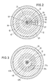
- the partial flows of material flowing in the circumferential direction are indicated by arrows in FIGS. 2 and 3 of the drawing.
- the material flow supplied through the feed channel 37 is divided into two partial material flows, which are each fed through the connecting channels 37a, 37b to an annular distributor channel 47a, 47b, so that two material flows are created and consequently at least two layers are present in the end laminate, which consist of the same material and come from an extruder.
- All of the annular channels 52, 53, 57b, 56, 57a, 50 opening into the storage space 30 are provided with end sections 62, 63, 67b, 66, 67a, 60, which expand conically in the direction of flow of the plastic flowing through the individual channel systems, the partition walls located between the ring channels experience a corresponding reduction in their thickness in the flow direction. This serves to reduce the speed of the individual material flows in these end sections 62, 63, 67b, 66, 67a, 60.
- the individual material flows are already brought closer to one another as they flow through these conically widening end sections, so that they pass through the respective outlet 72, 73, 77b, 76, 77a, 70 at the end boundary 28 of the annular piston 26, essentially through the ends of the walls delimiting the individual ring channels are defined, unite within the storage space 30 to form the end laminate.
- the end laminate formation point is thus within the storage space 30, but in direct connection to the outputs 72, 73, 77b, 76, 77a, 70 of the ring channels or the end sections thereof at the end face of the annular piston 26, which is located under the laminate formation the action of the storage space 30 filling laminate moves up until it has reached the end position shown in FIGS. 1 and 4. It is generally not necessary to close the extrusion opening 16, since the resistance that the annular piston 26 with its drive means 25, 27 opposes to the laminate filling the storage space 30 is normally less than the flow resistance of the extrusion opening 16.
- the drawing shows (FIG. 4) that the individual material flows at the moment they pass through the exits 72, 73, 77b, 76, 77a, 70 at the free end 28 of the annular piston 26 the entire width, that is to say the radial extent, of the storage space 30 to complete.
- This has the consequence that at the moment of the laminate formation, that is to say the connection of the individual material streams to the end laminate, only a slight transverse movement of the individual material streams is required in order to come into contact with one another and thereby connect to the end laminate.
- the end sections 62, 63, 67b, 66, 67a, 60 of the ring channels 52, 53, 57b, 56, 57a, 50 are also designed to widen conically in the direction of flow such that in the plane, in which the outputs 72, 73, 77b, 76, 77a, 70 lie, that is to say in the exemplary embodiment in the plane of the end face of the annular piston 26, the radial extent of the individual end sections is proportional to the thickness of the individual layers which are directed onto the outputs 72, 73, 77b, 76, 77a, 70 decrease material flows and that form in the storage space 30 end laminate.
- These layers are indicated in Fig.
- the arrangement is such that the material flows passing the exits extend over almost the entire width of the storage space 30, so that no noticeable transverse movements of the layers 82, 83, 87b, 86, 87a, 80 forming Material flows are required to combine them into the lamiant.
- annular piston 26 it is also not necessary to design the free end of the annular piston 26 so that the ends of all the partition walls run in a parting plane perpendicular to the longitudinal axis of the extrusion head.
- conditions that result from the required mechanical strength of the annular piston and the individual parts of the same could also be taken into account, although the annular piston is guided with its outer and inner lateral surfaces against the housing 10 or the mandrel 12, so that the outer partition walls, which are subject to one side due to the pressure of the plastic flows carried in the outer duct system 32, 42, 52, 62 or inner duct system 34, 45, 55, 50, are supported on the housing 10 or on the mandrel 12.
- the extrusion head described above works in the usual way.
- the procedure is such that the extruders from which the material flows are conveyed into the extrusion head continue to run, that is to say are operated continuously, even during the emptying stroke.
- FIG. 6 corresponds in terms of its construction and operation in all essential details to the embodiment of FIGS. 1-5, so that the same reference numerals are used for the same parts.
- the only difference between the two embodiments is that in the exemplary embodiment according to FIG. 6, the outlets 72, 73, 77b, 76, 77a, 70 of the channel systems located in the annular piston 26 have essentially the same radial extent. With layers of different widths in the final laminate to be formed within the storage space 30, the individual material flows would thus leave the exits at different speeds.
- the embodiment according to FIG. 6 will be applicable if the differences in the thickness of the individual layers are not too great and / or the absolute speeds at which the material flows pass the exits are so small that speed differences are not very significant fall. 6 has the advantage of a somewhat simpler construction.
Abstract
Description
Die Erfindung betrifft ein Verfahren und eine Vorrichtung zum Herstellen von Hohlkörpern aus thermoplastischen Kunststoffen, deren Wandung als Laminat ausgebildet ist, welches aus mehreren miteinander verbundenen Schichten aus wenigstens zwei Kunststoffen mit unterschiedlicher Beschaffenheit besteht, mittels Extrusions-Blasformen, wobei zunächst schlauchförmige Vorformlinge, deren Wandung eine entsprechende Anzahl von Schichten aufweist, die absatzweise hergestellt werden unter Verwendung einer Extrusionseinheit, die wenigstens zwei Extruder und einen gemeinsamen Extrusionskopf aufweist, der mit einem ringförmigen Speicherraum für das Laminat, einem ringförmigen Kolben zum Entleeren des Speicherraums und einer Extrusionsöffnung versehen ist, durch welche die Vorformlinge extrudiert werden, wobei alle in den Extrusionskopf eintretenden Materialströme, aus denen die einzelnen Schichten des Laminats gebildet werden, durch den ringförmigen Kolben geführt und in diesem in die Querschnittsform eines Ringes gebracht werden.The invention relates to a method and a device for producing hollow bodies made of thermoplastic materials, the wall of which is formed as a laminate, which consists of several interconnected layers of at least two plastics of different properties, by means of extrusion blow molding, firstly tubular preforms, the wall of which has a corresponding number of layers which are produced in batches using an extrusion unit which has at least two extruders and a common extrusion head which is provided with an annular storage space for the laminate, an annular piston for emptying the storage space and an extrusion opening through which the preforms are extruded, with all the material streams entering the extrusion head, from which the individual layers of the laminate are formed, passed through the annular piston and into this in di e cross-sectional shape of a ring are brought.
Bei einem durch die DE-OS 36 35 334 bekannten Verfahren zum Herstellen von Hohlkörpern aus thermoplastischem Kunststoff im Blasverfahren wird so vorgegangen, daß sämtliche Materialströme bereits innerhalb des Ringkolbens zum End-Laminat, aus welchem die Wandung des Hohlkörpers entsteht, miteinander verbunden werden und danach das so gebildete End-Laminat durch einen in Strömungsrichtung trichterförmig sich erweiternden ringförmigen Kanalab schnitt im Ringkolben in Richtung auf den Speicherraum strömt. In dem Bereich des Ringkolbens, in welchem die einzelnen Schichten zum End-Laminat verbunden werden, weist letzteres eine Dicke, also eine radiale Erstreckung auf, die wesentlich geringer ist als die radiale Erstreckung, also die Breite des Speicherraumes. Dieser Unterschied wird durch den in Strömungsrichtung konisch sich erweiternden Kanalabschnitt des Ringkolbens überbrückt, so daß das End-Laminat an der Mündung des Kanals annähernd die radiale Erstreckung des Speicherraums aufweist. Diese Verfahrensführung, bei welcher die einzelnen Materialströme zur Bildung des End-Laminats an einer Stelle zusammengeführt werden, an welcher das End-Laminat einen im Vergleich zur Breite des Speicherraumes nur geringe Dicke aufweist, um es dann innerhalb des Kolbens auf eine Dicke zu bringen, die nahezu der Breite des Speicherraumes entspricht, setzt einen Extrusionskopf voraus, der sehr lang baut, da der Kolben entsprechend lang dimensioniert sein muß. Außerdem hat eine Laminatbildungsstelle mit geringer radialer Erstreckung, also mit geringer Dicke des Laminats im Augenblick seiner Bildung, zur Folge, daß die einzelnen sich dort zum Laminat verbindenden Materialströme eine entsprechend hohe Geschwindigkeit aufweisen mit der Folge, daß zwischen den einzelnen Strömen vorhandene Geschwindigkeitsunterschiede im Augenblick der Laminatbildung entsprechend groß sind, denn die relativen Schichtdicken des Laminats ergeben sich aus den entsprechenden Verhältnissen der Materialströme. D. h., daß bei größeren Dickenunterschieden zwischen den einzelnen Schichten stark unterschiedliche Strömungsgeschwindigkeiten entstehen.In a method known from DE-OS 36 35 334 for the production of hollow bodies made of thermoplastic material in the blowing process, the procedure is such that all material flows are already connected to one another within the annular piston to form the end laminate from which the wall of the hollow body is formed, and thereafter the end laminate formed in this way through an annular channel which widens in the shape of a funnel cut in the ring piston flows towards the storage space. In the area of the annular piston in which the individual layers are connected to form the end laminate, the latter has a thickness, that is to say a radial extension, which is substantially less than the radial extension, that is to say the width of the storage space. This difference is bridged by the channel section of the annular piston, which widens conically in the flow direction, so that the end laminate at the mouth of the channel has approximately the radial extent of the storage space. This procedure, in which the individual material streams for forming the end laminate are brought together at a point at which the end laminate has only a small thickness compared to the width of the storage space, in order then to bring it to a thickness within the piston, which corresponds almost to the width of the storage space, requires an extrusion head that is very long since the piston must be dimensioned accordingly long. In addition, a laminate formation point with a small radial extension, that is to say with a small thickness of the laminate at the time of its formation, has the consequence that the individual material flows connecting to the laminate have a correspondingly high speed, with the result that there are instantaneous speed differences between the individual flows the laminate formation are correspondingly large, because the relative layer thicknesses of the laminate result from the corresponding ratios of the material flows. This means that with larger differences in thickness between the individual layers, very different flow velocities arise.
Demzufolge liegt der Erfindung die Aufgabe zugrunde, Verfahren und Vorrichtung der einleitend beschriebenen Art so auszugestalten, daß bei möglichst kurzer Bauweise des Extrusionskopfes ein End-Laminat hergestellt werden kann, welches möglichst gleichmäßig ausgebildet und frei von Störungen ist.The invention is therefore based on the object of designing a method and apparatus of the type described in the introduction in such a way that the construction of the Extrusion head an end laminate can be produced, which is formed as evenly as possible and free of interference.
Zur Lösung dieser Aufgabe schlägt die Erfindung vor, daß die den Ringkolben an seinem der Extrusionsöffnung zugekehrten Ende verlassenden, im Querschnitt ringförmigen Materialströme einzeln aus dem Ringkolben in den Speicherraum fließen und sich in letzterem zum Laminat vereinigen. Zweckmäßig wird dabei so verfahren, daß die Materialströme stirnseitig aus dem Ringkolben austreten, so daß die Materialströme, die jeweils die äußere und innere Schicht des Laminats bilden, mit der äußeren bzw. inneren Begrenzungswandung des Speicherraumes erst im Augenblick der Laminatbildung in Berührung kommen. Auf diese Weise kann erreicht werden, daß das gespeicherte End-Laminat nach seiner Bildung gegenüber der Wandung des Speicherraumes bis zum folgenden Entleerungshub keine wesentliche Bewegung ausführt. Diese begünstigt die Gleichmäßigkeit der Ausbildung des End-Laminats. Zudem wird durch die Laminatbildung im Speicherraum bei entsprechender Bemessung der Breite des Laminatbildungsbereichs vermieden, daß der Ringkolben mit einem besonderen kanalabschnitt versehen sein muß, innerhalb dessen das Laminat in Fließrichtung auf die radiale Erstreckung des Speicherraumes gebracht wird. Vielmehr ist es nach einem weiteren Vorschlag der Erfindung möglich, daß die radiale Erstreckung des Laminatbildungsbereiches annähernd der radialen Erstreckung des Speicherraums entspricht. D. h., daß die Gesamtheit der den Ringkolben an seiner der Extrusionsöffnung des Extrusionskopfes zugekehrten Ende verlassenden Materialströme beim Eintreten in den Speicherraum eine radiale Erstreckung aufweist, die annähernd der radialen Erstreckung des Speicherraumes entspricht. Eine derartige Verfahrensführung hat den Vorteil, daß das Laminat im allgemeinen im Augenblick seiner Bildung seine größte Dicke aufweist und im Zuge der weiteren Verformungen zum Vorformling im wesentlichen nur eine Verringerung seiner Dicke erfährt. Dieses stellt einen Streckvorgang dar, der immer eindeutig ist. Eine Vergrößerung der Dicke des Laminats erfordert einen Quell-oder Stauchvorgang bzw. Quell- oder Stauchströmungen, bei welchen die Gefahr besteht, daß das Laminat mit seinen verschiedenartigen Schichten gestört wird. Dieses Problem ist immer vorhanden, so daß man bestrebt ist, die erforderlichen Umformungen innerhalb des Extrusionskopfes als Dickenreduzierung oder Streckung des Laminats durchzuführen.To achieve this object, the invention proposes that the material flows ring-shaped in cross-section from the ring piston at its end facing the extrusion opening, flow individually from the ring piston into the storage space and unite in the latter to form a laminate. Appropriately, the procedure is such that the material flows emerge from the face of the annular piston, so that the material flows, which each form the outer and inner layers of the laminate, come into contact with the outer and inner boundary walls of the storage space only at the moment of the laminate formation. In this way it can be achieved that the stored final laminate does not perform any significant movement after it has been formed relative to the wall of the storage space until the following emptying stroke. This favors the uniformity of the formation of the final laminate. In addition, with the appropriate dimensioning of the width of the laminate formation area, the laminate formation in the storage space prevents the annular piston from being provided with a special channel section within which the laminate is brought to the radial extent of the storage space in the direction of flow. Rather, according to a further proposal of the invention, it is possible that the radial extent of the laminate formation area corresponds approximately to the radial extent of the storage space. This means that the entirety of the material flows leaving the annular piston at its end facing the extrusion opening of the extrusion head has a radial extent when entering the storage space, which corresponds approximately to the radial extent of the storage space. Such a procedure has the advantage that the laminate is generally in the moment its formation has its greatest thickness and, in the course of the further deformations to the preform, essentially only experiences a reduction in its thickness. This represents a stretching process that is always unique. An increase in the thickness of the laminate requires a swelling or upsetting process or swelling or upsetting currents in which there is a risk that the laminate with its various layers will be disturbed. This problem is always present, so that efforts are made to carry out the necessary reshaping within the extrusion head as a reduction in thickness or stretching of the laminate.
Der vorbeschriebenen Verfahrensführung, bei welcher die radiale Erstreckung des Laminatbildungsbereiches annähernd der radialen Erstreckung des Speicherraumes entspricht, sind insoweit Grenzen gesetzt, als die Festigkeit der zwischen den einzelnen Ringkanälen innerhalb des Kolbens befindlichen Trennwände und auch der äußeren und der inneren Begrenzungswand des Kolbens zu berücksichtigen ist. Eine weitestgehende Annäherung an die vorstehend genannte Bedingung wird normalerweise dadurch erreicht werden können, daß die Materialströme unmittelbar vor Verlassen des Ringkolbens an dessen der Extrusionsöffnung zugekehrten Stirnseite eine radiale Verbreiterung erfahren derart, daß sie in dem Bereich, in welchem sie den Ringkolben verlassen, nur noch durch schmale Zwischenräume, die durch die Trennwände innerhalb des Kolbens gebildet werden, voneinander getrennt sind.The procedure described above, in which the radial extent of the laminate formation area approximately corresponds to the radial extent of the storage space, is limited in so far as the strength of the partition walls located between the individual ring channels within the piston and also the outer and inner boundary wall of the piston must be taken into account . The greatest possible approximation to the above-mentioned condition can normally be achieved in that the material streams undergo a radial widening immediately before leaving the annular piston on its end face facing the extrusion opening in such a way that they only in the area in which they leave the annular piston are separated from each other by narrow spaces, which are formed by the partitions within the piston.
Für die Qualität des zu bildenden Laminats, insbesondere dessen Regelmäßigkeit bezüglich Verteilung und Positionierung der einzelnen Schichten sowie ser gleichmäßigen Dicke derselben, ist auch die Geschwindigkeit der einzelnen Ströme im Laminatbildungsbereich von großer Bedeutung. Die Geschwindigkeiten, mit denen die einzelnen Schichten im Laminatbildungsbereich aufeinandertreffen und miteinander verbunden werden, sollten möglichst nicht voneinander abweichen. Zumindest sollten die Unterschiede zwischen den Geschwindigkeiten der einzelnen Materialströme insbesondere im Laminatbildungsbereich so gering wie nur irgend möglich sein. Im Hinblick auf dieses Erfordernis schlägt die Erfindung weiterhin vor, daß die Dicke, also die radiale Dimension, der den Kolben verlassenden einzelnen Materialströme im wesentlichen proportional ist der Dicke der aus ihnen zu bildenden Schichten in dem im Speicherraum gespeicherten End-Laminat.For the quality of the laminate to be formed, in particular its regularity with regard to the distribution and positioning of the individual layers and the uniform thickness thereof, the speed of the individual streams in the laminate formation area is also of great importance. The Speeds with which the individual layers meet in the laminate formation area and are connected to one another should preferably not differ from one another. At least the differences between the speeds of the individual material flows, especially in the laminate formation area, should be as small as possible. In view of this requirement, the invention further proposes that the thickness, ie the radial dimension, of the individual material flows leaving the piston is essentially proportional to the thickness of the layers to be formed from them in the end laminate stored in the storage space.
Im Extrusionsblasverfahren hergestellte Hohlkörper, insbesondere Behälter, werden in vielen Fällen mehrschichtig hergestellt, damit die Wandung des Hohlkörpers unterschiedlichen Anforderungen genügt, die von einem einzigen Kunststoff nicht erfüllt werden können. Als Beispiel seinen Kraftstofftanks genannt, die einmal eine ausreichende mechanische Festigkeit aufweisen müssen, ohne daß jedoch der Kraftstoff durch die Behälterwandung in merklichen Mengen diffundieren darf. Die die mechanische Festigkeit betreffenden Eigenschaften werden bei gleichzeitiger Berücksichtigung wirtschaftlicher Erfordernisse derzeit am ehesten durch zur Gruppe der Polyolefine gehörenden Kunstsstoffe erfüllt. Das in vielen Fällen verwendete Polyethylen weist jedoch den Nachteil auf, daß es Kraftstoff hindurchdiffundieren läßt. Deshalb wird die Wandung eines Kraftstofftanks ggf. mit einer Diffusionssperre in Form einer Schicht beipsielsweise aus Polyamid versehen. Da eine Schicht aus Polyethylen einerseits und eine Schicht aus Polyamid andererseits jedoch kaum eine feste Verbindung miteinander eingehen, ist es erforderlich, zwischen beiden Schichten eine Haftvermittlerschicht anzuordnen. Das Material dieser Haftvermittlerschicht geht eine ausreichend feste Verbindung sowohl mit beispielsweise Polyäthylen als auch Polyamid ein und hat im wesentlichen nur die Funktion, beide letztgenannten Schichten in ausreichend fester Weise miteinander zu verbinden.Hollow bodies, in particular containers, produced in the extrusion blow molding process are in many cases produced in multiple layers, so that the wall of the hollow body meets different requirements that cannot be met by a single plastic. One example is his fuel tanks, which must have sufficient mechanical strength, but without the fuel being allowed to diffuse through the container wall in appreciable amounts. The properties relating to mechanical strength, while taking economic requirements into account, are currently best met by plastics belonging to the group of polyolefins. However, the polyethylene used in many cases has the disadvantage that it allows fuel to diffuse through. Therefore, the wall of a fuel tank is optionally provided with a diffusion barrier in the form of a layer, for example made of polyamide. However, since a layer of polyethylene on the one hand and a layer of polyamide on the other hand hardly form a firm connection with one another, it is necessary to arrange an adhesion promoter layer between the two layers. The material of this adhesive layer works a sufficiently strong connection both with, for example, polyethylene and polyamide and essentially has only the function of connecting the latter two layers with one another in a sufficiently firm manner.
In Abhängigkeit von den jeweiligen Anforderungen und den den einzelnen Schichten zugedachten Funktionen kann ein derartiges End-Laminat sieben und mehr Schichten aufweisen, wobei die einzelnen Schichten wiederum in Abhängigkeit von ihrer Funktion und der Beschaffenheit des sie bildenden Materials unterschiedlich dick sein können. So wird bzw. werden die Schicht(en) aus Polyolefin bei dem vorgenannten Beipsiel wesentlich dicker sein als die Sperrschicht(en), die das Hindurchdiffundieren vermeiden soll(en) und die Haftvermittlerschicht(en), die zudem beide aus Materialien bestehen, die wesentlich teurer sind als beipsielsweise Polyethylen, das in vielen Fällen für die die mechanische Festigkeit bestimmende Trägerschicht(en) der Wand verwendet wird.Depending on the respective requirements and the functions intended for the individual layers, such an end laminate can have seven or more layers, the individual layers again being able to have different thicknesses depending on their function and the nature of the material forming them. In the aforementioned example, the layer (s) made of polyolefin will be much thicker than the barrier layer (s), which should prevent diffusion through and the adhesion promoter layer (s), both of which also consist of materials that are essential are more expensive than, for example, polyethylene, which is used in many cases for the support layer (s) of the wall that determine the mechanical strength.
Bekannte Verfahren tragen diesem Sachverhalt keine Rechnung. Es wird häufig davon ausgegangen, daß sämtliche Schichten des End-Laminats gleich dick sind. Dies ist zumindest für die Mehrzahl der praktischen Anwendungen von Hohlkörpern mit einer mehrschichtigen Wandung unrealistisch, da aus den genannten Gründen ein Laminat, dessen Schichten bezüglich ihrer Dicke nicht oder nur wenig voneinander abweichen, in der Praxis, und sei es lediglich aus wirtschaftlichen Gründen, häufig nicht verwendet werden kann.Known procedures do not take this into account. It is often assumed that all layers of the final laminate are of the same thickness. This is unrealistic, at least for the majority of practical applications of hollow bodies with a multi-layer wall, since for the reasons mentioned a laminate, the layers of which do not or only slightly differ in terms of their thickness, is common in practice, even if only for economic reasons cannot be used.
Wenn die den Ringkolben verlassenden Materialströme im Augenblick des Eintretens in den Speicherraum annähernd gleiche Querschnitte aufweisen, können unterschiedliche Dicken der das Laminat bildenden Schichten nur dadurch erreicht werden, daß die einzelnen Materialströme mit unterschiedlichen Geschwindigkeiten aus dem Ringkolben austreten, wobei die Geschwindigkeitsunterschiede bei der vorgenannten Voraussetzung etwa den Unterschieden bei den Schichtdicken entsprechen. Da die Unterschiede bezüglich der Dicke der einzelnen Schichten sehr groß sein, beispielsweise im Verhältnis von mehr als 1 : 10 zueinander stehen können, würden die Geschwindigkeitsunterschiede zwischen den einzelnen Materialströmen an der Laminatbildungsstelle entsprechend groß sein. Dabei ist es kaum möglich, ein Laminat zu bilden, dass hohen Qualitätsansprüchen genügt. Insoweit kommt dem Vorschlag der Erfindung, die Dicke der Materialströme im Laminatbildungsbereich zumindest annähernd proportional zu den Dicken der einzelnen Schichten im End-Laminat zu wählen, für die Herstellung von qualitativ hochwertigen Hohlkörpern eine besondere Bedeutung zu.If the material flows leaving the annular piston have approximately the same cross-sections at the moment they enter the storage space, this can only result in different thicknesses of the layers forming the laminate can be achieved that the individual material flows emerge from the annular piston at different speeds, the speed differences in the aforementioned condition approximately correspond to the differences in the layer thicknesses. Since the differences in the thickness of the individual layers can be very large, for example in a ratio of more than 1:10 to one another, the speed differences between the individual material flows at the laminate formation point would be correspondingly large. It is hardly possible to form a laminate that meets high quality standards. In this regard, the proposal of the invention to choose the thickness of the material flows in the laminate formation area at least approximately proportional to the thicknesses of the individual layers in the final laminate is of particular importance for the production of high-quality hollow bodies.
Da in vielen Fällen die Schichten, denen keine tragende Funktion zukommt, sehr dünn sein können, ggf. nur den Bruchteil eines Millimeters dick zu sein brauchen, wird es normalerweise erforderlich sein, die Schichtdicke im Bereich des Austrittes der Materialströme aus dem Ringkolben größer zu wählen als in dem im Speicherraum zu bildenden Laminat, da es aus fertigungstechnischen Gründen kaum möglich ist, Kanäle mit einer derart geringen radialen Erstreckung herzustellen. Dies ist jedoch weniger nachteilig, da mit der Wahl insgesamt größerer Schichtdicken in diesem Bereich eine Verringerung der absoluten Strömungsgeschwindigkeit einhergeht, so daß ggf. doch vorhandene Geschwindigkeitsunterschiede ohnehin weniger stark ins Gewicht fallen. Auf jeden Fall sind die Verhältnisse um ein Vielfaches günstiger als bei einer dünnen Laminatbildungs stelle, da die herstellungstechnischen Schwierigkeiten zur Erzielung entsprechend angepaßter Abmessungen im Ringkolben abnehmen.Since in many cases the layers that do not have a supporting function can be very thin, possibly only need to be a fraction of a millimeter thick, it will normally be necessary to choose a larger layer thickness in the area where the material flows out of the ring piston than in the laminate to be formed in the storage space, since it is hardly possible for manufacturing reasons to produce ducts with such a small radial extent. However, this is less disadvantageous since the choice of overall greater layer thicknesses in this area is accompanied by a reduction in the absolute flow velocity, so that any differences in velocity that may be present are less important anyway. In any case, the conditions are many times more favorable than with thin laminate formations place, since the manufacturing difficulties decrease to achieve correspondingly adapted dimensions in the annular piston.
Die Tatsache, daß das im Speicherraum gebildete und dort befindliche End-Laminat im allgemeinen eine wesentlich größere Dicke aufweist als die Wandung des daraus herzustellenden Hohlkörpers ist, wie bereits erwähnt, vorteilhaft. Die Verringerung der Laminatdicke auf die Dicke der Wandung des Hohlkörpers erfolgt normalerweise in mehreren Schritten. So erfährt das Laminat beim Passieren der ringförmigen Extrusionsöffnung eine erhebliche Verringerung seiner Dicke. Weiterhin wird normalerweise das die Wandung des durch die Extrusionsöffnung ausgestoßenen Vorformlings bildende Laminat eine weitere Verringerung seiner Dicke erfahren, wenn der Vorformling innerhalb einer Blasform durch inneren Überdruck zum blasgeformten Erzeugnis aufgeweitet wird.The fact that the end laminate formed in the storage space and located there generally has a substantially greater thickness than the wall of the hollow body to be produced therefrom is advantageous, as already mentioned. The reduction of the laminate thickness to the thickness of the wall of the hollow body usually takes place in several steps. Thus, the laminate experiences a significant reduction in its thickness as it passes through the annular extrusion opening. Furthermore, normally the laminate forming the wall of the preform ejected through the extrusion opening will experience a further reduction in its thickness if the preform is expanded within a blow mold to internal pressure to the blow molded product.
In Abhängigkeit von den jeweilige Erfordernissen oder Bedingungen kann es sinnvoll sein, wenigstens zwei Material-Teilströme bereits im Kolben zu einem Vorlaminat zu vereinigen, welches dann in Form eines einzigen Materialstroms aus dem Ringkolben in den Speicherraum eintritt. D. h., daß die Materialströme, die aus dem freien Stirnende des Kolben austreten können, ihrerseits bereits aus zwei oder mehr Schichten bestehen können, die einen zusammenhängenden Materialstrom bilden. Das Erfordernis, zwei oder mehr Material-Teilströme zu einem ein Vorlaminat darstellenden Materialstrom zu vereinigen, kann sich z. B. daraus ergeben, daß der im Querschnitt des Ringkolbens verfügbare Raum nicht ausreicht, um für sämtliche einzelnen Materialströme jeweils ein Kanalsystem vorzusehen, welches bis zum freien, stirnseitigen Ende des Ringkolbens geführt werden kann. Zweckmäßigerweise wird eine Vorlaminatbildung mit Materialien durchgeführt, die gleich oder gleichartig sind und/oder deren Materialströme sich nicht wesentlich voneinander unterscheiden. Ein solches Vorlaminat kann sinnvollerweise zur Herstellung von Laminatschichten benutzt werden, bei welchen die durch die Schlauchbildung hervorgerufenen Zusammenflußlinien zueinander versetzt angeordnet sein sollen, um zu erreichen, daß die Zusammenflußlinie nur einen Teil der Dicke jeder ein Vorlaminat bildenden Schicht durchsetzt. Ein derartiges Vorlaminat wird in der Regel aus dem gleichen Material hergestellt oder einem Material gleichen Typs, wobei dann vorteilhaft beide Materialströme die gleiche Dicke besitzen. Darüber hinaus ist es sinnvoll, z. B. den Materialstrom für eine Barriereschicht sowie die beiden Materialströme für die zugeführten Haftvermittlerschichten zu einem Vorlaminat zu vereinigen. Alle drei Schichten sind in der Regel annähernd gleich dick. Dies bedeutet, daß die jeweiligen Materialströme mit im wesentlichen gleichen Geschwindigkeiten zusammengeführt werden. Da diese Schichten, wie bereits erwähnt, sehr dünn sein können, kann durch Herstellen des Vorlaminat eine Schichtdicke erzielt werden, die zu günstigeren Verhältnissen für das Einführen dieses Vorlaminats in den Speicherraum zur Bildung des End-Laminates führt.Depending on the respective requirements or conditions, it may be useful to combine at least two partial material flows in the piston to form a prelaminate, which then enters the storage space in the form of a single material flow from the annular piston. This means that the material flows, which can emerge from the free end of the piston, in turn can already consist of two or more layers, which form a coherent material flow. The need to combine two or more partial material streams to form a pre-laminate material stream may arise, for. B. result from the fact that the space available in the cross section of the annular piston is not sufficient to provide a channel system for each individual material flow, which can be guided up to the free, front end of the annular piston. A pre-laminate is expediently used Materials carried out that are the same or similar and / or whose material flows do not differ significantly from each other. Such a prelaminate can usefully be used to produce laminate layers in which the confluence lines caused by the hose formation are to be arranged offset from one another in order to ensure that the confluence line penetrates only part of the thickness of each layer forming a prelaminate. Such a prelaminate is generally produced from the same material or from a material of the same type, in which case both material streams advantageously have the same thickness. In addition, it is useful, for. B. to combine the material flow for a barrier layer and the two material flows for the supplied adhesion promoter layers to form a prelaminate. All three layers are usually approximately the same thickness. This means that the respective material flows are brought together at essentially the same speeds. Since these layers, as already mentioned, can be very thin, a layer thickness can be achieved by producing the prelaminate, which leads to more favorable conditions for the introduction of this prelaminate into the storage space for the formation of the final laminate.
Die Vorrichtung zum Herstellen von Hohlkörpern unter Anwendung des vorbeschriebenen Verfahrens kann so ausgebildet sein, daß innerhalb des Ringkolbens Kanalsysteme angeordnet sind, die an einem Ende mit wenigstens einer Zuführungsleitung für Kunststoffmaterial verbunden sind und sich innerhalb des Ringkolbens in Strömungsrichtung des Materials in einen im Querschnitt ringförmigen Kanalabschnitt fortsetzen, der an dem der Extrusionsöffnung zugekehrten Ende des Ringkolbens über einen ringförmigen Ausgang in den Speicherraum mündet, wobei die an der Stirnseite des Ringkolbens befindlichen Ausgänge für die Materialströme voneinander getrennt in den Speicherraum münden. Die Anzahl der Zuführungsleitungen für die Kanalsysteme kann mit der Anzahl der getrennt voneinander in den Speicherraum mündenden Ausgänge übereinstimmen. Es ist aber auch möglich, daß die Anzahl der Zuführungsleitungen kleiner - wenn wenigstens einer der durch die Zuführungsleitungen zugeführten Materialströme geteilt wird - oder größer ist - wenn aus wenigstens zwei durch die Zuführungsleitungen zugeführten Materialströme ein Vorlaminat gebildet wird - als die Anzahl der getrennt voneinander in den Speicherraum mündenden Ausgänge. Bei gleichzeitiger Anwendung beider Maßnahmen kann natürlich auch der Fall eintreten, daß die Anzahl der Zuführungsleitungen für die Kanalsysteme mit der Anzahl der getrennt voneinander in den Speicherraum mündenden Ausgänge übereinstimmt. Weiterhin ist es vorteilhaft, daß die radiale Erstreckung des Bereiches, innerhalb dessen die Ausgänge an der dem Speicherraum zugekehrten Stirnfläche des Ringkolbens angeordnet sind, annähernd der radialen Breite des Speicherraumes entspricht. Darüber hinaus können die einzelnen Ausgänge im Bereich ihrer Mündung in den Speicherraum eine Breite aufweisen, die im wesentlichen proportional ist der Dicke der Schichten im Laminat, die aus den die Ausgänge an der Stirnseite des Kolbens jeweils verlassenden Materialströmen gebildet werden.The device for producing hollow bodies using the method described above can be designed such that channel systems are arranged within the annular piston, which are connected at one end to at least one feed line for plastic material and within the annular piston in the flow direction of the material in a ring-shaped in cross section Continue channel section, which opens at the end of the ring piston facing the extrusion opening via an annular outlet into the storage space, the at the Outputs for the material flows located at the end of the annular piston separate into the storage space. The number of supply lines for the channel systems can correspond to the number of outputs which separate from one another into the storage space. However, it is also possible that the number of feed lines is smaller - if at least one of the material flows fed through the feed lines is divided - or greater - if at least two material flows fed through the feed lines form a prelaminate - than the number of the separately in exits opening into the storage space. If both measures are used at the same time, the case can of course also occur that the number of supply lines for the channel systems corresponds to the number of outputs which separate from one another into the storage space. It is also advantageous that the radial extent of the area within which the outputs are arranged on the end face of the annular piston facing the storage space approximately corresponds to the radial width of the storage space. In addition, the individual exits in the region of their mouth into the storage space can have a width which is essentially proportional to the thickness of the layers in the laminate which are formed from the material flows leaving the exits at the end face of the piston.
Um den Extrusionskopf bei einem Wechsel von der Herstellung einer Hohlkörperart auf die Herstellung einer anderen Hohlkörperart schnell und ohne großen Aufwand an eine andere Verteilung der Schichtdicken anpassen zu können, kann es zweckmäßig sein, den dem Speicherraum zugekehrten Endabschnitt des Ringkolbens, der die Ausgänge der Kanalsysteme enthält, auswechselbar am Kolben anzubringen, um auf diese Weise eine schnelle Umstellung auf andere Schichtdicken und somit andere im Bereich ihrer Ausgänge bezüglich ihrer Breite dazu proportionale Kanalsysteme zu ermöglichen.In order to be able to adapt the extrusion head quickly and without great effort to a different distribution of the layer thicknesses when changing from the production of one type of hollow body to the production of another type of hollow body, it may be expedient to adjust the end section of the annular piston facing the storage space, which is the outlet of the channel systems contains, interchangeable to attach to the piston, in this way a quick change to others Layer thicknesses and thus allow other duct systems proportional to their width in the area of their outputs.
In der Zeichnung sind zwei derzeit bevorzugte Ausführungsbeispiele der Erfindung in Schema dargestellt. Es zeigen:
- Fig. 1 im Schema die Seitenansicht eines Extrusionskopfes, teilweise im Schnitt, mit dem Ringkolben in seiner Stellung bei gefülltem Speicherraum,
- Fig. 2 einen Schnitt nach der Linie II-II der Fig. 1,
- Fig. 3 einen Schnitt nach der Linie III-III der Fig. 1,
- Fig. 4 einen Ausschnitt aus Fig. 1 im Längsschnitt und in größerem Maßstab,
- Fig. 5 eine der Fig. 3 entsprechende Darstellung, jedoch mit dem Ringkolben in seiner Stellung bei entleertem Speicherraum,
- Fig. 6 eine der Fig. 4 entsprechende Darstellung einer zweiten Ausführungsform.
- 1 is a schematic side view of an extrusion head, partly in section, with the ring piston in its position when the storage space is full,
- 2 shows a section along the line II-II of FIG. 1,
- 3 shows a section along the line III-III of FIG. 1,
- 4 shows a detail from FIG. 1 in longitudinal section and on a larger scale,
- 5 shows a representation corresponding to FIG. 3, but with the annular piston in its position when the storage space is empty,
- Fig. 6 is a representation corresponding to FIG. 4 of a second embodiment.
Der Extrusionskopf des Ausführungsbeispiels gemäß den Fig. 1 - 5 weist in der üblichen Weise ein Gehäuse 10 auf, innerhalb dessen ein dazu koaxialer Dorn 12 angeordnet ist, der an seinem unteren Ende ein Paßstück 14 trägt, welches den zur ringförmigen Extrusionsöffnung 16 führenden Ringkanal 18 innenseitig begrenzt. Innerhalb des Paßstückes 14 ist ein Düsenkern 19 geführt, der gemeinsam mit dem ihn umgebenden Düsenring 20 die Extrusionsöffnung 16 begrenzt. Der Düsenkern wird von einer Stange 22 getragen, die innerhalb des Dornes 12 geführt und an ihrer der Extrusionsöffnung 16 abgekehrten Ende mit dem Kolben 23 eines hydraulischen Zylinders 24 verbunden ist. Durch entsprechende Beaufschlagung des Kolbens 23 kann der Düsenkern 19 axial nach oben und unten zur Beeinflussung der Breite der Extrusionsöffnung 16 verschoben werden. Dies wird in der üblichen Weise dadurch ermöglicht, daß die einander gegenüberliegenden Flächen des Düsenkerns 19 und des ihn umgebenden Düsenringes 20 konisch verlaufend ausgebildet sind.The extrusion head of the exemplary embodiment according to FIGS. 1-5 has, in the usual way, a
Innerhalb des Gehäuses 10 ist ein Ringkolben 26 axial hin- und herverchiebbar angeordnet. Der Ringkolben 26 ist an seinem der Extrusionsöffnung abgekehrten Endbereich mit der Kolbenstange 21 eines Kolbens 25 verbunden, der in einem hydraulischen Zylinder 27 geführt ist. Es können mehrere Kolben-Zylinder-Anordnungen 25, 27 vorgesehen sein, von denen in der Zeichnung jedoch nur eine dargestellt ist. Es ist auch möglich, nur eine Kolben-Zylinder-Anordnung vorzusehen, die dann so angeordnet sein würde, daß sie den Ringkolben 26 symmetrisch beaufschlagt.Within the
In den Figuren 1 und 4 nimmt der Ringkolben seine obere Endlage ein, in welcher seine der Extrusionsöffnung 16 zugekehrte Stirnseite 28 einen Speicherraum 30 oberseitig begrenzt, der im Gehäuse 10 im Bereich zwischen der Stirnseite 28 des Ringkolbens 26 und dem Paßstück 14 vorgesehen ist. Fig. 5 zeigt die untere Endlage des Ringkolbens 26, in die er durch die Zylinder-Kolben-Anordnungen 25, 27 verschoben wird.In FIGS. 1 and 4, the annular piston assumes its upper end position, in which its
Der Extrusionskopf ist mit sechs in der Zeichnung nicht dargestellten Extrudern verbunden, aus denen jeweils ein thermoplastisches Kunststoffmaterial oder ein anderes Material mit gleichen Eigenschaften bezüglich der Verarbeitbarkeit in den Extrusionskopf gefördert wird. Diese Extruder sind in geeigneter Weise mit innerhalb des Ringkolbens 26 angeordneten Kanalsystemen verbunden. Wie im einzelnen die Verbindung erfolgt, ist nicht Gegenstand der Erfindung. So ist beispielsweises eine Verbindung zwischen den Austrittsöffnungen der Extruder und den innerhalb des Ringkolbens 26 angeordneten Kanalsystemen in der in der DE-OS 36 35 334 beschriebenen Weise möglich. Andere Möglichkeiten der Verbindung sind z. B. in der DE-AS 21 61 356, in der DE-PS 26 39 665 und in der DE-PS 30 26 822 beschrieben.The extrusion head is connected to six extruders, not shown in the drawing, from each of which a thermoplastic material or another material with the same properties with regard to processability is conveyed into the extrusion head. These extruders are connected in a suitable manner to channel systems arranged inside the
Jeder der von den Extrudern kommenden Materialströme gelangt innerhalb des Kolbens 26 jeweils in einem im Querschnitt etwa kreisförmigen Zuführkanal 32, 33, 34, 35, 36, 37. Diese Zuführkanäle sind im wesentlichen parallel zur Längsachse des Extrusionskopfes verlaufend angeordnet. Die auf einem Radius des Ringkolbens angeordneten Zuführkanäle 32, 33, 34, 35 münden in koaxial zur Längsachse des Extrusionskopfes und in radialen Abständen voneinander angeordneten ringförmigen Verteilerkanälen 42, 43, 44, 45 , die in einer gemeinsamen, zur Längsachse des Extrusionskopfes senkrechten Ebene umlaufenden. Der auf demselben Radius angeordnete Zuführkanal 36 mündet in einem ringförmigen Verteilerkanal 46, der innerhalb des Ringkolbens 36 in einer zur Längsachse des Extrusionskopfes senkrechten Ebene umläuft, die sich in einem geringeren Abstand vom freien Ende 28 des Ringkolbens befindet als die Verteilerkanäle 42, 43, 44, 45. Der Zuführkanal 37, der gegenüber den anderen Zuführkanälen in Umfangsrichtung des Querschnittes des Extrusionskopfes versetzt angeordnet ist, setzt sich in zwei Verbindungskanäle 37a, 37b fort, die jeweils in einem ringförmigen Verteilerkanal 47a, 47b münden. Die ringförmigen Verteilerkanäle 47a, 47b sind in derselben Ebene angeordnet wie der ringförmige Verteilerkanal 46. Der Ringkolben 36 enthält somit insgesamt sieben ringförmige Verteilerkanäle, die aus Platzgründen aus zwei einen axialen Abstand voneinander aufweisenden Ebenen angeordnet sind. In den Verteilerkanälen wird der in Form eines geschlossenen Stranges durch die im Querschnitt vorzugsweise kreisförmigen Zuführkanäle jeweils zugeführte Materialstrom zu einem im Querschnitt ringförmigen Materialstrom umgeformt.Each of the material flows coming from the extruders arrives inside the
An jeden der Verteilerkanäle 42, 43, 44, 45, 46, 47a, 47b schließt sich jeweils ein Ringkanal 52, 53, 54, 55, 56, 57a, 57b an, wobei sämtliche Ringkanäle mit Ausnahme der Ringkanäle 54, 55 am stirnseitigen Ende 28 des Ringkolbens 26 in den Speicherraum 30 münden. Die Ringkanäle 54 und 55 münden in den Sammel-Ringkanal 50, so daß die die Ringkanäle 54, 55 durchströmenden Materialströme sich im Bereich ihrer Mündungen in den Sammel-Ringkanal 50 zu einem Vorlaminat vereinigen, welches aus zwei Schichten besteht. Die vorbeschriebene Ausgestaltung, bei welcher den beiden Ringkanälen 54, 55 ein gemeinsamer Sammel-Ringkanal 50 nachgeordnet ist, kann z. B. dann erforderlich sein, wenn die Querschnittsfläche des Ringkolbens 36 zu klein ist, als daß sämtliche Ringkanäle bis zum freien Ende des Kolbens fortgesetzt werden können. Ein anderer Grund für eine solche Ausgestaltung kann darin bestehen, daß in dem im Sammel-Ringkanal 50 sich bildenden Vorlaminat eine durchgehende Zusammenfluß-Naht vermieden werden soll, die an der Stelle entsteht, an welcher im Verteilerkanal die beiden in Umfangsrichtung den jeweiligen Verteilerkanal durchströmenden Material-Teilströme aufeinandertreffen und sich zu einem geschlossenen Ring verbinden. Diese Stelle wird im allgemeinen um 180° C gegenüber dem jeweiligen Zuführkanal in Umfangsrichtung versetzt angeordnet sein. In diesem Fall, also bei Bildung eines Vorlaminats zur Vermeidung einer durchgehenden Naht, werden jedoch die beiden Zuführkanäle 34, 35 für die Zufuhr der beiden das Vorlaminat bildenden Materialströme in Umfangsrichtung gegeneinander versetzt angeordnet sein, um die in den Materialströmen sich bildenden Nähte in Umfangsrichtung etwas gegeneinander zu versetzen. Die in Umfangsrichtung fließenden Material-Teilströme sind in den Fig. 2 und 3 der Zeichnung durch Pfeile angedeutet.Each of the
Der durch den Zuführkanal 37 zugeführte Materialstrom wird hingegen in zwei Material-Teilströme unterteilt, die durch die Verbindungskanäle 37a, 37b jeweils einem ringförmigen Verteilerkanal 47a, 47b zugeführt werden, so daß zwei Materialströme entstehen und demzufolge im End-Laminat wenigstens zwei Schichten vorhanden sind, die aus gleichem Material bestehen und von einem Extruder stammen.The material flow supplied through the
Sämtliche in den Speicherraum 30 mündende Ringkanäle 52, 53, 57b, 56, 57a, 50 sind mit Endabschnitte 62, 63, 67b, 66, 67a, 60 versehen, die sich in Strömungsrichtung des durch die einzelnen Kanalsysteme fließenden Kunststoffes konisch erweitern, wobei die zwischen den Ringkanälen befindlichen Trennwände in Strömungsrichtung eine entsprechende Verringerung ihrer Dicke erfahren. Dies dient einmal dazu, die Geschwindigkeit der einzelnen Materialströme in diesen Endabschnitten 62, 63, 67b, 66, 67a, 60 zu verringern. Zum anderen werden dadurch die einzelnen Materialströme bereits beim Durchfließen dieser konisch sich erweiternden Endabschnitte einander angenähert, so daß sie beim Passieren des jeweiligen Ausgangs 72, 73, 77b, 76, 77a, 70 an der stirnseitigen Begrenzung 28 des Ringkolbens 26, die im wesentlichen durch die Enden der die einzelnen Ringkanäle begrenzenden Wandungen definiert ist, sich innerhalb des Speicherraumes 30 zum End-Laminat vereinigen. Die End-Laminatbildungsstelle liegt somit innerhalb des Speicherraumes 30, jedoch in unmittelbarem Anschluß an die Ausgänge 72, 73, 77b, 76, 77a, 70 der Ringkanäle bzw. der Endabschnitte derselben am stirnseitigen Ende des des Ringkolbens 26, der sich bei der Laminatbildung unter der Einwirkung des den Speicherraum 30 füllenden Laminats nach oben verschiebt, bis er die Endlage gemäß den Fig. 1 und 4 erreicht hat. Dabei ist es in der Regel nicht erforderlich, die Extrusionsöffnung 16 zu verschließen, da der Widerstand, den der Ringkolben 26 mit seinen Antriebsmitteln 25, 27 dem den Speicherraum 30 füllenden Laminat entgegensetzt, normalerweise kleiner ist als der Strömungswiderstand der Extrusionsöffnung 16.All of the
Der Zeichnung läßt erkennen (Fig. 4), daß die einzelnen Materialströme im Augenblick des Passierens der Ausgänge 72, 73, 77b, 76, 77a, 70 am freien Ende 28 des Ringkolbens 26 die gesamte Breite, also die radiale Erstreckung, des Speicherraumes 30 ausfüllen. Dies hat zur Folge, daß im Augenblick der Laminatbildung, also der Verbindung der einzelnen Materialströme zum End-Laminat, nur geringfügige Querbewegung der einzelnen Materialströme erforderlich sind, um miteinander in Berührung zu kommen und sich dabei zum End-Laminat zu verbinden. Dies begünstigt ebenfalls die Gleichmäßigkeit der Laminatbildung und damit des dabei entstehenden Laminates, zumal während des Speicherns das Laminat innerhalb des Speicherraumes 30 ruht, also im wesentlichen unbewegt bleibt und somit während der Laminatbildung die Bewegung der die einzelnen Schichten bildenden Materialströme sich auf die innerhalb des Ringkolbens überwiegend in axialer Richtung verlaufende Bewegung beschränkt, deren Geschwindigkeit aufgrund der konischen Erweiterung der Endabschnitte 62, 63, 67b, 66, 67a, 60 innerhalb derselben ohnehin verhältnismäßig gering ist.The drawing shows (FIG. 4) that the individual material flows at the moment they pass through the
Sobald der Ringkolben 26 während des Füllvorganges seine in den Figuren 1 und 4 dargestellte obere Endlage erreicht hat, in welcher der Speicherraum 30 mit dem End-Laminat gefüllt ist, wird der Ringkolben 26 durch Beaufschlagen des Kolbens 25 in üblicher Weise in Richtung auf die Ex trusionsöffnung 16 bewegt, wobei im Zuge dieser Hubbewegung gleichzeitig das im Speicherraum 30 gespeicherte Laminat in Richtung auf die Extrusionsöffnung 16 verschoben wird, bis der Ringkolben 26 seine in Fig. 5 dargestellte untere Endposition erreicht hat. Bis zum Passieren der Extrusionsöffnung 16 erfährt das Laminat im wesentlichen eine Reduzierung seiner radialen Ausdehnung, da die Spaltbreite des ringförmigen Kanals 18 bis zur Estrusionsöffnung 16 kleiner wird als die Breite des Speicherraumes 30. Es hat sich jedoch herausgestellt, daß die dadurch bewirkte stetige Abnahme der Dicke des Laminats wesentlich günstiger ist als ein Wechsel zwischen Verringerung und Vergrößerung oder umgekehrt der Dicke des Laminats.As soon as the
Beim Ausführungsbeispiel gemäß den Fig. 1 bis 5 sind überdies die Endabschnitte 62, 63, 67b, 66, 67a, 60 der Ringkanäle 52, 53, 57b, 56, 57a, 50 derart konisch in Strömungsrichtung sich erweiternd ausgebildet, daß in der Ebene, in welcher die Ausgänge 72, 73, 77b, 76, 77a, 70 liegen, also beim Ausführungsbeispiel in der Ebene der Stirnfläche des Ringkolbens 26, die radiale Erstreckung der einzelnen Endabschnitte proportional ist der Dicke der einzelnen Schichten, die auf die die Ausgänge 72, 73, 77b, 76, 77a, 70 verlassenden Materialströme zurückgehen und daß im Speicherraum 30 gespeicherte End-Laminat bilden. Diese Schichten sind in Fig. 4 der Zeichnung angedeutet und mit 82, 83, 87b, 86, 87a und 80 bezeichnet. Aufgrund der vorbeschriebenen relativen Breite der Ausgänge 72, 73, 77b, 76, 77a, 70 wird erreicht, daß die Materialströme im Augenblick des Passierens der Ausgänge im wesentlichen gleiche Geschwindigkeiten aufweisen, so daß im Augenblick der Laminatbildung, die dadurch bewirkt wird, daß der Ringkolben 26 im Verlauf des Füllens des Speicherraums 30 von der Extrusionsöffnung 16 wegbewegt wird, keine merklichen Geschwindigkeitsunterschiede zwischen den einzelnen Materialströmen vorhanden sind. Zudem ist, wie bereits erwähnt, die Anordnung so getroffen, daß die die Ausgänge passierenden Materialströme sich insgesamt über nahezu die gesamte Breite des Speicherraums 30 erstrecken, so daß keine merklichen Querbewegungen der die Schichten 82, 83, 87b, 86, 87a, 80 bildenden Materialströme erforderlich sind, um sie zum Lamiant zu vereinigen.In the exemplary embodiment according to FIGS. 1 to 5, the
Im übrigen ist es auch nicht erforderlich, das freie Ende des Ringkolbens 26 so auszubilden, daß die Enden sämtlicher Trennwände in einer zur Längsachse des Extrusionskopfes senkrechten Trennebene verlaufen. Hier könnten ggf. auch Bedingungen, die sich aus der erforderlichen mechanischen Festigkeit des Ringkolbens sowie der einzelnen Teile desselben ergeben, Berücksichtigung finden, wenngleich der Ringkolben mit seiner äußeren und seiner inneren Mantelfläche am Gehäuse 10 bzw. am Dorn 12 anliegend geführt ist, so daß die außen liegenden Trennwände, die einseitig durch den Druck des im äußeren Kanalsystem 32, 42, 52, 62 bzw. inneren Kanalsystem 34, 45, 55, 50 geführten Kunststoffströme unterliegen, am Gehäuse 10 bzw. am Dorn 12 eine Abstützung erfahren.Moreover, it is also not necessary to design the free end of the
Im übrigen arbeitet der vorbeschriebene Extrusionskopf in der üblichen Weise. D. h., daß nach dem Entleerungshub, in dessen Verlauf der Ringkolben 26 aus der Position gemäß Fig. 4 in die gemäß Fig. 5 axial verschoben wird, das aus den Ausgängen des Ringkolbens 26 austretende Material den Ringkolben nach oben in seine in Fig. 4 dargestellte Ausgangslage verschiebt, wobei gleichzeitig der Speicherraum 30 mit dem Laminat gefüllt wird. Im allgemeinen wird so verfahren, daß auch während des Entleerungshubes die Extruder, aus denen die Materialströme in den Extrusionskopf gefördert werden, weiterlaufen, also kontinuierlich betrieben werden.Otherwise, the extrusion head described above works in the usual way. In other words, after the emptying stroke, during which the
Das in Fig. 6 dargestellte Ausführungsbeispiel entspricht bezüglich seines konstruktiven Aufbaus und seines Betriebs in allen wesentlichen Einzelheiten dem Ausführungsbeispiel gemäß Fig. 1 - 5, so daß für gleiche Teile auch gleiche Bezugszeichen verwendet werden. Der einzige Unterschied zwischen beiden Ausführungsformen besteht darin, daß beim Ausführungsbeispiel gemäß Fig. 6 die Ausgänge 72, 73, 77b, 76, 77a, 70 der im Ringkolben 26 befindlichen Kanalsysteme im wesentlichen die gleiche radiale Erstreckung aufweisen. Bei unterschiedlich breiten Schichten in dem innerhalb des Speicherraums 30 zu bildenden End-Laminat würden somit die einzelnen Materialströme die Ausgänge mit unterschiedlichen Geschwindigkeiten verlassen. Die Ausführungsform gemäß Fig. 6 wird dann anwendbar sein, wenn die Unterschiede bezüglich der Dicke der einzelnen Schichten nicht allzu groß sind und/oder die absoluten Geschwindigkeiten, mit welchen die Materialströme die Ausgänge passieren, so gering ist, daß Geschwindigkeitsunterschiede nicht sehr stark ins Gewicht fallen. Der Kolben gemäß Fig. 6 weist den Vorteil eines etwas einfacheren Aufbaus auf.The embodiment shown in FIG. 6 corresponds in terms of its construction and operation in all essential details to the embodiment of FIGS. 1-5, so that the same reference numerals are used for the same parts. The only difference between the two embodiments is that in the exemplary embodiment according to FIG. 6, the
Claims (11)
Priority Applications (1)
| Application Number | Priority Date | Filing Date | Title |
|---|---|---|---|
| AT89111570T ATE82188T1 (en) | 1988-07-04 | 1989-06-24 | METHOD AND DEVICE FOR PRODUCTION OF HOLLOW BODIES FROM THERMOPLASTIC PLASTIC. |
Applications Claiming Priority (2)
| Application Number | Priority Date | Filing Date | Title |
|---|---|---|---|
| DE3822524A DE3822524A1 (en) | 1988-07-04 | 1988-07-04 | METHOD AND DEVICE FOR PRODUCING HOLLOW BODIES FROM THERMOPLASTIC PLASTICS |
| DE3822524 | 1988-07-04 |
Publications (2)
| Publication Number | Publication Date |
|---|---|
| EP0349872A1 true EP0349872A1 (en) | 1990-01-10 |
| EP0349872B1 EP0349872B1 (en) | 1992-11-11 |
Family
ID=6357883
Family Applications (1)
| Application Number | Title | Priority Date | Filing Date |
|---|---|---|---|
| EP89111570A Expired - Lifetime EP0349872B1 (en) | 1988-07-04 | 1989-06-24 | Method and apparatus for the manufacture of hollow bodies from thermoplastics material |
Country Status (7)
| Country | Link |
|---|---|
| US (1) | US5004578A (en) |
| EP (1) | EP0349872B1 (en) |
| JP (1) | JP2824665B2 (en) |
| AT (1) | ATE82188T1 (en) |
| CA (1) | CA1320319C (en) |
| DE (2) | DE3822524A1 (en) |
| ES (1) | ES2035449T3 (en) |
Cited By (1)
| Publication number | Priority date | Publication date | Assignee | Title |
|---|---|---|---|---|
| WO1991018731A1 (en) * | 1990-06-01 | 1991-12-12 | Mauser-Werke Gmbh | Storage head for a blow moulding machine |
Families Citing this family (12)
| Publication number | Priority date | Publication date | Assignee | Title |
|---|---|---|---|---|
| DE3831837A1 (en) * | 1988-09-20 | 1990-03-22 | Kautex Maschinenbau Gmbh | METHOD AND DEVICE FOR PRODUCING HOLLOW BODIES FROM THERMOPLASTIC PLASTIC |
| DE3831836A1 (en) * | 1988-09-20 | 1990-03-22 | Kautex Maschinenbau Gmbh | METHOD AND DEVICE FOR PRODUCING HOLLOW BODIES FROM THERMOPLASTIC PLASTIC |
| US5202074A (en) * | 1989-12-26 | 1993-04-13 | The Dow Chemical Company | Method for producing injection molded multilayer articles |
| US5380479A (en) * | 1989-12-26 | 1995-01-10 | The Dow Chemical Company | Method and apparatus for producing multilayer plastic articles |
| DE4020819A1 (en) * | 1990-06-29 | 1990-11-08 | Bock Stefan Dipl Ing Fh | STORAGE HEAD FOR THE PRODUCTION OF SINGLE OR MULTILAYER HOSE-OVER-HOSE STRUCTURED PREFORMS FROM THERMOPLASTICS |
| JP2694063B2 (en) * | 1991-04-15 | 1997-12-24 | 株式会社日本製鋼所 | Extrusion control method for multi-layer parison |
| US5662842A (en) | 1994-07-18 | 1997-09-02 | Salflex Polymers Ltd. | Process for blow molding hollow objects with independent movement of mold halves |
| US6261400B1 (en) | 1997-04-09 | 2001-07-17 | Spalding Sports Worldwide, Inc. | Method of manufacturing multi-layer game ball |
| US5776519A (en) * | 1997-06-06 | 1998-07-07 | Graham Engineering Corporation | Parison extrusion head with quick change die ring clamp assembly |
| US20060038310A1 (en) * | 2004-07-29 | 2006-02-23 | Erik Lipson | Method and apparatus for forming extruded striped plastic products with variations in width of the stripes along the length of the products and for blow molding articles formed from such extruded parts |
| CN109352952B (en) * | 2018-10-31 | 2021-03-16 | 徐州耐克盾机械制造有限公司 | Storage type die head of multilayer co-extrusion blow molding machine |
| CN109352951A (en) * | 2018-10-31 | 2019-02-19 | 徐州耐克盾机械制造有限公司 | A kind of Multifunctional blow-molding machine die head |
Citations (8)
| Publication number | Priority date | Publication date | Assignee | Title |
|---|---|---|---|---|
| US3985490A (en) * | 1974-06-04 | 1976-10-12 | Mauser Kommanditgesellschaft | Apparatus for extruding a homogeneous tubular length of soft thermoplastic material |
| DE2617898A1 (en) * | 1976-04-23 | 1977-11-03 | Reiner Dipl Ing Kader | Oblique extruder head for thermoplastic tubes - has annular reservoir with discharge piston and supply duct incorporated in the piston |
| FR2354188A1 (en) * | 1976-06-09 | 1978-01-06 | Feuerherm Harald | COOKING HEAD FOR THE PRODUCTION OF A THERMO-PLASTIC TUBE |
| DE2712911A1 (en) * | 1977-03-24 | 1978-09-28 | Mauser Kg | Plastics tube injection head - has annular piston moving in storage chamber fitted with supply duct connecting chamber with plastics supply source |
| US4297092A (en) * | 1980-06-30 | 1981-10-27 | Midland-Ross Corporation | Accumulator head used in the formation of a multi-layer parison |
| US4548569A (en) * | 1984-08-06 | 1985-10-22 | Somerset Technologies, Inc. | Accumulator head |
| EP0249866A2 (en) * | 1986-06-14 | 1987-12-23 | BEKUM Maschinenfabriken GmbH | Accumulator head for manufacturing multilayer coextruded plastic hoses |
| WO1988002689A2 (en) * | 1986-10-17 | 1988-04-21 | Richter Guenther | Process and device for producing large hollow plastic bodies with multilayered walls |
Family Cites Families (8)
| Publication number | Priority date | Publication date | Assignee | Title |
|---|---|---|---|---|
| DE1704791B2 (en) * | 1968-03-18 | 1976-07-29 | Kautex Werke Reinold Hagen Gmbh, 5300 Bonn-Holzlar | DEVICE FOR THE PRODUCTION OF CROSS-SECTION RING-SHAPED BODIES FROM THERMOPLASTIC PLASTIC |
| DE2639665C2 (en) * | 1976-09-03 | 1983-11-10 | Harald 5210 Troisdorf Feuerherm | Extrusion head for producing a hollow strand from thermoplastic material |
| DE2712910A1 (en) * | 1977-03-24 | 1978-09-28 | Mauser Kg | Multicomponent plastics tube injection head - has storage chamber supplied with components each moving along dynamically identical path from extruder to chamber |
| US4422838A (en) * | 1979-12-27 | 1983-12-27 | Ishikawajima-Harima Jukogyo Kabushiki Kaisha | Extrusion head for use in blow molding machine |
| DE3026822C2 (en) * | 1980-07-16 | 1985-02-21 | Reiner Dipl.-Ing. 5205 St.Augustin Kader | Angle spray head for making a hose |
| DE3305242A1 (en) * | 1983-02-16 | 1984-08-16 | Battenfeld-Fischer Blasformtechnik GmbH, 5204 Lohmar | PINOLE FOR THE THORN OF A HOSE HEAD FOR THE PRODUCTION OF HOSE SECTIONS OR HOSES FROM THERMOPLASTIC PLASTIC |
| DE3623308A1 (en) * | 1986-07-11 | 1988-01-28 | Battenfeld Fischer Blasform | Extruder head for producing composite flexible tubes from various thermoplastic materials |
| US4874305A (en) * | 1988-11-03 | 1989-10-17 | Somerset Technologies, Inc. | Accumulator extrusion head for producing striped parisons |
-
1988
- 1988-07-04 DE DE3822524A patent/DE3822524A1/en not_active Withdrawn
-
1989
- 1989-06-24 DE DE8989111570T patent/DE58902663D1/en not_active Expired - Lifetime
- 1989-06-24 EP EP89111570A patent/EP0349872B1/en not_active Expired - Lifetime
- 1989-06-24 ES ES198989111570T patent/ES2035449T3/en not_active Expired - Lifetime
- 1989-06-24 AT AT89111570T patent/ATE82188T1/en not_active IP Right Cessation
- 1989-06-30 US US07/375,167 patent/US5004578A/en not_active Expired - Lifetime
- 1989-07-04 JP JP1172825A patent/JP2824665B2/en not_active Expired - Lifetime
- 1989-07-04 CA CA000604740A patent/CA1320319C/en not_active Expired - Fee Related
Patent Citations (8)
| Publication number | Priority date | Publication date | Assignee | Title |
|---|---|---|---|---|
| US3985490A (en) * | 1974-06-04 | 1976-10-12 | Mauser Kommanditgesellschaft | Apparatus for extruding a homogeneous tubular length of soft thermoplastic material |
| DE2617898A1 (en) * | 1976-04-23 | 1977-11-03 | Reiner Dipl Ing Kader | Oblique extruder head for thermoplastic tubes - has annular reservoir with discharge piston and supply duct incorporated in the piston |
| FR2354188A1 (en) * | 1976-06-09 | 1978-01-06 | Feuerherm Harald | COOKING HEAD FOR THE PRODUCTION OF A THERMO-PLASTIC TUBE |
| DE2712911A1 (en) * | 1977-03-24 | 1978-09-28 | Mauser Kg | Plastics tube injection head - has annular piston moving in storage chamber fitted with supply duct connecting chamber with plastics supply source |
| US4297092A (en) * | 1980-06-30 | 1981-10-27 | Midland-Ross Corporation | Accumulator head used in the formation of a multi-layer parison |
| US4548569A (en) * | 1984-08-06 | 1985-10-22 | Somerset Technologies, Inc. | Accumulator head |
| EP0249866A2 (en) * | 1986-06-14 | 1987-12-23 | BEKUM Maschinenfabriken GmbH | Accumulator head for manufacturing multilayer coextruded plastic hoses |
| WO1988002689A2 (en) * | 1986-10-17 | 1988-04-21 | Richter Guenther | Process and device for producing large hollow plastic bodies with multilayered walls |
Cited By (2)
| Publication number | Priority date | Publication date | Assignee | Title |
|---|---|---|---|---|
| WO1991018731A1 (en) * | 1990-06-01 | 1991-12-12 | Mauser-Werke Gmbh | Storage head for a blow moulding machine |
| US5256051A (en) * | 1990-06-01 | 1993-10-26 | Mauser-Werke Gmbh | Storage head for a blow molding machine |
Also Published As
| Publication number | Publication date |
|---|---|
| US5004578A (en) | 1991-04-02 |
| DE58902663D1 (en) | 1992-12-17 |
| ES2035449T3 (en) | 1993-04-16 |
| CA1320319C (en) | 1993-07-20 |
| JP2824665B2 (en) | 1998-11-11 |
| EP0349872B1 (en) | 1992-11-11 |
| ATE82188T1 (en) | 1992-11-15 |
| DE3822524A1 (en) | 1990-01-11 |
| JPH0270405A (en) | 1990-03-09 |
Similar Documents
| Publication | Publication Date | Title |
|---|---|---|
| DE2733913C2 (en) | Method and apparatus for producing a multilayer injection molded body from thermoplastic synthetic resins | |
| EP0326584B1 (en) | Process and device for producing large hollow plastic bodies with multilayered walls | |
| EP1183145B1 (en) | Device for producing extrusion blow-molded containers with at least two chambers | |
| EP0361187B1 (en) | Method and apparatus for manufacturing hollow bodies from a thermoplastic material | |
| EP0249866B1 (en) | Accumulator head for manufacturing multilayer coextruded plastic hoses | |
| EP0349872B1 (en) | Method and apparatus for the manufacture of hollow bodies from thermoplastics material | |
| DE1629364B2 (en) | METHOD AND DEVICE FOR EXTRUDING A COMPOSITE SHEET MADE OF THERMOPLASTIC PLASTICS | |
| DE4211552C2 (en) | Method and device for extruding a multilayer parison | |
| EP0995579A2 (en) | Method for continuous production of a composite pipe with socket and apparatus for carrying out the method | |
| EP0465889B1 (en) | Apparatus for manufacturing hollow thermoplastic bodies | |
| EP0274095B1 (en) | Co-extrusion head | |
| WO2014195337A1 (en) | Extrusion parison head for discontinuous foaming | |
| DE3439285A1 (en) | Blow-moulded tubes with projections - produced by feeding melt to recess in one mould cavity extruding tubular parison into cavity applying second mould tool and blowing | |
| DE4225011B4 (en) | Device for producing a metal-plastic composite pipe | |
| DE1261657B (en) | Spray head for the production of tubular stretches | |
| DE3902270A1 (en) | METHOD AND DEVICE FOR THE DISCONTINUOUS PRODUCTION OF MULTILAYERED, COEXTRUDED, TUBULAR PREFORMINGS FROM THERMOPLASTIC PLASTIC | |
| DE3044535A1 (en) | Laminated plastic extrusions - dual tool produces one polymer inside another and extrudes combination to required profile | |
| EP0923445A1 (en) | Drum-like container out of plastic and process and device for its production | |
| EP0407847B1 (en) | Method and apparatus for manufacturing hollow thermoplastic bodies | |
| DE19545441B4 (en) | Apparatus for producing a hose-like preform and molded part produced from the preform | |
| DE2143597A1 (en) | Extrusion device for the production of synthetic resin composite structures or laminates | |
| DE4135336C2 (en) | Process for extruding multilayer pipes | |
| EP1334815B1 (en) | Apparatus for extruding plastic tubes with low friction nozzle | |
| DE102021118705A1 (en) | Device and process for biaxial plastic extrusion | |
| EP1388406B1 (en) | Method and apparatus for making blow-moulded hollow articles from thermoplastics |
Legal Events
| Date | Code | Title | Description |
|---|---|---|---|
| PUAI | Public reference made under article 153(3) epc to a published international application that has entered the european phase |
Free format text: ORIGINAL CODE: 0009012 |
|
| AK | Designated contracting states |
Kind code of ref document: A1 Designated state(s): AT BE CH DE ES FR GB GR IT LI LU NL SE |
|
| 17P | Request for examination filed |
Effective date: 19900626 |
|
| 17Q | First examination report despatched |
Effective date: 19910930 |
|
| ITF | It: translation for a ep patent filed |
Owner name: FIAMMENGHI - DOMENIGHETTI |
|
| GRAA | (expected) grant |
Free format text: ORIGINAL CODE: 0009210 |
|
| AK | Designated contracting states |
Kind code of ref document: B1 Designated state(s): AT BE CH DE ES FR GB GR IT LI LU NL SE |
|
| PG25 | Lapsed in a contracting state [announced via postgrant information from national office to epo] |
Ref country code: SE Effective date: 19921111 Ref country code: NL Effective date: 19921111 Ref country code: GR Free format text: LAPSE BECAUSE OF FAILURE TO SUBMIT A TRANSLATION OF THE DESCRIPTION OR TO PAY THE FEE WITHIN THE PRESCRIBED TIME-LIMIT Effective date: 19921111 Ref country code: BE Effective date: 19921111 |
|
| REF | Corresponds to: |
Ref document number: 82188 Country of ref document: AT Date of ref document: 19921115 Kind code of ref document: T |
|
| GBT | Gb: translation of ep patent filed (gb section 77(6)(a)/1977) | ||
| REF | Corresponds to: |
Ref document number: 58902663 Country of ref document: DE Date of ref document: 19921217 |
|
| ET | Fr: translation filed | ||
| NLV1 | Nl: lapsed or annulled due to failure to fulfill the requirements of art. 29p and 29m of the patents act | ||
| REG | Reference to a national code |
Ref country code: ES Ref legal event code: FG2A Ref document number: 2035449 Country of ref document: ES Kind code of ref document: T3 |
|
| PG25 | Lapsed in a contracting state [announced via postgrant information from national office to epo] |
Ref country code: LU Free format text: LAPSE BECAUSE OF NON-PAYMENT OF DUE FEES Effective date: 19930630 Ref country code: LI Effective date: 19930630 Ref country code: CH Effective date: 19930630 |
|
| PLBI | Opposition filed |
Free format text: ORIGINAL CODE: 0009260 |
|
| 26 | Opposition filed |
Opponent name: BATTENFELD FISCHER BLASFORMTECHNIK GMBH Effective date: 19930810 |
|
| REG | Reference to a national code |
Ref country code: CH Ref legal event code: PL |
|
| PLBN | Opposition rejected |
Free format text: ORIGINAL CODE: 0009273 |
|
| STAA | Information on the status of an ep patent application or granted ep patent |
Free format text: STATUS: OPPOSITION REJECTED |
|
| 27O | Opposition rejected |
Effective date: 19950221 |
|
| PGFP | Annual fee paid to national office [announced via postgrant information from national office to epo] |
Ref country code: ES Payment date: 20010528 Year of fee payment: 13 |
|
| PGFP | Annual fee paid to national office [announced via postgrant information from national office to epo] |
Ref country code: GB Payment date: 20010620 Year of fee payment: 13 |
|
| PGFP | Annual fee paid to national office [announced via postgrant information from national office to epo] |
Ref country code: FR Payment date: 20010621 Year of fee payment: 13 |
|
| PGFP | Annual fee paid to national office [announced via postgrant information from national office to epo] |
Ref country code: AT Payment date: 20010625 Year of fee payment: 13 |
|
| PGFP | Annual fee paid to national office [announced via postgrant information from national office to epo] |
Ref country code: DE Payment date: 20010822 Year of fee payment: 13 |
|
| REG | Reference to a national code |
Ref country code: GB Ref legal event code: IF02 |
|
| PG25 | Lapsed in a contracting state [announced via postgrant information from national office to epo] |
Ref country code: GB Free format text: LAPSE BECAUSE OF NON-PAYMENT OF DUE FEES Effective date: 20020624 Ref country code: AT Free format text: LAPSE BECAUSE OF NON-PAYMENT OF DUE FEES Effective date: 20020624 |
|
| PG25 | Lapsed in a contracting state [announced via postgrant information from national office to epo] |
Ref country code: ES Free format text: LAPSE BECAUSE OF NON-PAYMENT OF DUE FEES Effective date: 20020625 |
|
| PG25 | Lapsed in a contracting state [announced via postgrant information from national office to epo] |
Ref country code: DE Free format text: LAPSE BECAUSE OF NON-PAYMENT OF DUE FEES Effective date: 20030101 |
|
| GBPC | Gb: european patent ceased through non-payment of renewal fee |
Effective date: 20020624 |
|
| PG25 | Lapsed in a contracting state [announced via postgrant information from national office to epo] |
Ref country code: FR Free format text: LAPSE BECAUSE OF NON-PAYMENT OF DUE FEES Effective date: 20030228 |
|
| REG | Reference to a national code |
Ref country code: FR Ref legal event code: ST |
|
| REG | Reference to a national code |
Ref country code: ES Ref legal event code: FD2A Effective date: 20030711 |
|
| PG25 | Lapsed in a contracting state [announced via postgrant information from national office to epo] |
Ref country code: IT Free format text: LAPSE BECAUSE OF NON-PAYMENT OF DUE FEES;WARNING: LAPSES OF ITALIAN PATENTS WITH EFFECTIVE DATE BEFORE 2007 MAY HAVE OCCURRED AT ANY TIME BEFORE 2007. THE CORRECT EFFECTIVE DATE MAY BE DIFFERENT FROM THE ONE RECORDED. Effective date: 20050624 |