EP0348956B1 - A device for the exclusive use of a single telephone line by a telephone set in installations comprising a plurality of telephone sets - Google Patents
A device for the exclusive use of a single telephone line by a telephone set in installations comprising a plurality of telephone sets Download PDFInfo
- Publication number
- EP0348956B1 EP0348956B1 EP89111802A EP89111802A EP0348956B1 EP 0348956 B1 EP0348956 B1 EP 0348956B1 EP 89111802 A EP89111802 A EP 89111802A EP 89111802 A EP89111802 A EP 89111802A EP 0348956 B1 EP0348956 B1 EP 0348956B1
- Authority
- EP
- European Patent Office
- Prior art keywords
- line
- telephone
- telephone set
- voltage
- condition
- Prior art date
- Legal status (The legal status is an assumption and is not a legal conclusion. Google has not performed a legal analysis and makes no representation as to the accuracy of the status listed.)
- Expired - Lifetime
Links
Images

Classifications
-
- H—ELECTRICITY
- H04—ELECTRIC COMMUNICATION TECHNIQUE
- H04M—TELEPHONIC COMMUNICATION
- H04M1/00—Substation equipment, e.g. for use by subscribers
- H04M1/68—Circuit arrangements for preventing eavesdropping
- H04M1/70—Lock-out or secrecy arrangements in party-line systems
Definitions
- the present invention relates to subscribers' telephone installations and more particularly to a device for the exclusive use of a single telephone line by a telephone set in installations comprising a plurality of telephone sets, such device being connected between the telephone line and each telephone set, and comprising means for assigning the line to the first set who goes into off-hook condition and for isolating the others till said first set goes into on-hook condition again, without any priority determined by the insertion points of the telephone sets on the line.
- EP-A 0 182 393, US-A 4 747 128 and US-A 4 322 983 show a prior art technique, to be seen easiest in EP-A 182 393.
- the telephone set is connected in series with a bridge rectifier circuit, the bridge diagonal being short-circuited by a thyristor which is triggered via a voltage divider in series with a zener diode, which series connection is connected in parallel to the thyristor.
- a voltage divider in series with a zener diode, which series connection is connected in parallel to the thyristor.
- an independent resistor for causing a voltage drop.
- Such combination does not fully isolate the telephone set from the line, especially if the line is not perfectly balanced, so that listening to a conversation taking place at a different telephone set can not be fully excluded.
- DE-A 36 28 922 shows a privacy protector technique, in this case using a single device controlling a plurality of telephones.
- the device operates a plurality of switches connected each in series with one of the telephone sets.
- the disadvantages of the prior art techniques are overcome by the device provided by the present invention, which allows the secrecy of a call originated from a telephone set to be maintained regardless of its point of insertion on the line and which does not require the use of special plugs or additional contacts in the telephone sets, which can be of the two-wire type: this is of advantage from the installation simplicity and cost standpoint.
- the device is considerably simple and therefrom cheap, and is easy to manufacture as an integrated circuit.
- the device also comprises means for signalling the seized line condition, connected to the isolating circuit and operated when such a circuit isolates the telephone set from the line; useless seizure attempts are so avoided and there is immediately signalled when the line becomes idle again.
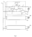
- References a and b in Fig. 1 denote the two wires forming a conventional telephone line; TF1, TF2...TFn denote n telephone sets sharing said line, DI1, DI2...DIn denote n devices according to the invention, each connected between the line and a telephone set.
- the device comprises: a voltage sensor SV which can discriminate between open circuit line voltage and seized line voltage; a current sensor SI capable of detecting whether the current flowing in it reaches a value corresponding to telephone off hook condition; a circuit IS capable of isolating telephone set TF1 from the line when the latter is seized, but the handset is on hook; a circuit S signalling the isolated condition of said telephone set.
- References 1 - 7 denote the wires connecting the circuits in DI1 to one another, to line a, b and to the telephone set.
- the telephone sets are considered to be equivalent to the series of a resistor and a switch, which is open when the handset is on hook and closed when the handset is off hook.
- the voltage between line wires a and b is about the same as the telephone exchange battery voltage (typically 60 or 48 V); sensor SV recognizes that such a voltage corresponds to the idle state and through conductor 5 brings isolating circuit IS into such conditions that said isolating circuit connects conductors 1 and 3; since current sensor SI, as will be better seen in Fig.2, is designed so as always to allow current flow between conductors 2 and 4, telephone set TF1 is connected to the line. Similarly, all remaining telephone sets are connected to said line, so that the arrival of a possible call operates the ringer of all sets.
- isolating circuit IS isolate telephone set TF1.
- isolating circuit IS is such that it is operated (i.e. it isolates the telephone set) only if the line is seized while the handset is not off hook; therefore, under the described condition conductors 1 and 3 remain connected and telephone set TF1 can normally effect the call.
- FIG. 2 A possible circuit embodiment of the device is shown in Fig. 2, which also indicates the individual functional blocks SV, SI, S and IS, already described with reference to the preceding Figure.
- Block SV is composed of transistor T1, resistors R1 and R2 and zener diode Z1.
- the threshold voltage of Z1 lies between idle line voltage and seized line voltage; as a consequence, if the line is idle, the zener diode is conducting and transistor T1 saturates, while if the line is seized Z1 does not conduct and T1 remains inhibited.
- the resistances of resistors R1 and R2 are sufficiently high in order the current flowing in them is not considered by the telephone exchange as being due to a poor line insulation.
- Current sensor SI consists of transistor T4 together with diodes D3 and D4 and resistors R6 and R7.
- Diodes D3, D4, as shown, keep the circuit between conductors 2 and 4 always closed. If no current flows from conductor 3 to conductor 2 through conductor 4 (on hook condition), there is no voltage drop across diodes D3 - D4 and hence transistor T4 is inhibited; if on the contrary there is a current flow between conductors 3 and 4, transistor T4 saturates.
- Diode D5 allows a current flow also in the reverse direction, what takes place during the arrival of the a.c. ringing current, while capacitor C has smoothing functions to avoid oscillatory phenomena of the whole device.
- Isolating circuit IS is made of transistors T2 and T3, resistors R3 and R5 and diodes D1, D2. If at least one of transistors T1 and T4 is saturated, transistor T2 is inhibited; under these conditions transistor T3, operating as an emitter follower, transfers onto conductor 3 the voltage present on conductor 1, thus extending the line towards the telephone set connected between conductors 3 and 4. If on the contrary both transistors T1 and T4 are inhibited, T2 saturates, thereby inhibiting T3 and short-circuiting conductors 3 and 2 via diode D1 and T2 itself; hence the telephone set placed between conductors 3 and 4 remains completely isolated. Diode D2 allows the reverse flow of the ringing current, exactly alike D5.
- Signalling circuit 5 extracts the voltage across resistor R5 through wires 7′ and 7 ⁇ forming connection 7 of Fig. 1.
- Circuit S is composed of light-emitting diode LD, while transistor T5, together with zener diode Z2 and resistors R8 and R9, forms a current generator.
- led LD is traversed by a constant current, independently of the applied voltage itself, and emits light, thereby signalling the line seizure.
- Fig. 2 clearly shows the simplicity of the device according to the invention; it is also evident that the device, which is formed solely of diodes, transistors, resistors and capacitors and comprises a very limited number of components, can be easily manufactured as an integrated circuit.
Landscapes
- Engineering & Computer Science (AREA)
- Signal Processing (AREA)
- Sub-Exchange Stations And Push- Button Telephones (AREA)
- Telephonic Communication Services (AREA)
Description
- The present invention relates to subscribers' telephone installations and more particularly to a device for the exclusive use of a single telephone line by a telephone set in installations comprising a plurality of telephone sets, such device being connected between the telephone line and each telephone set, and comprising means for assigning the line to the first set who goes into off-hook condition and for isolating the others till said first set goes into on-hook condition again, without any priority determined by the insertion points of the telephone sets on the line.
- In telephone installations using a single line, such as those installed in private subscribers' premises, a plurality of telephone sets, e. g. one set in each room of the house, is often desired. Were the sets simply connected in parallel to the line, call secrecy will be impossible, since all sets would receive the same signals. To overcome this disadvantage, the sets in multiple-set installations are usually cascaded; moreover particular switch contacts are provided, which are operated by the hook and are so arranged that, when the handset is lifted, the connection towards downstream sets is interrupted and the downstream line is short-circuited to avoid cross-talk. This solution optimally resolves the problem of secrecy in respect of downstream telephone sets, but not as far as upstream telephone sets are concerned: in fact, if the handset of an upstream telephone is lifted, the latter replaces the others in the conversation, clearly disturbing the person who was making a call. In addition this system is expensive, since each telephone set must be equipped with switching contacts and with three connection wires; if the set is equipped with a plug, special three-pole plugs are necessary, capable of automatically extending the line when the telephone set is disconnected.
- Furthermore EP-A 0 182 393, US-A 4 747 128 and US-A 4 322 983 show a prior art technique, to be seen easiest in EP-A 182 393. Therein, the telephone set is connected in series with a bridge rectifier circuit, the bridge diagonal being short-circuited by a thyristor which is triggered via a voltage divider in series with a zener diode, which series connection is connected in parallel to the thyristor. In series with the telephone set, there is also an independent resistor for causing a voltage drop. Such combination does not fully isolate the telephone set from the line, especially if the line is not perfectly balanced, so that listening to a conversation taking place at a different telephone set can not be fully excluded.
- Also DE-A 36 28 922 shows a privacy protector technique, in this case using a single device controlling a plurality of telephones. The device operates a plurality of switches connected each in series with one of the telephone sets.
- The disadvantages of the prior art techniques are overcome by the device provided by the present invention, which allows the secrecy of a call originated from a telephone set to be maintained regardless of its point of insertion on the line and which does not require the use of special plugs or additional contacts in the telephone sets, which can be of the two-wire type: this is of advantage from the installation simplicity and cost standpoint. In addition the device is considerably simple and therefrom cheap, and is easy to manufacture as an integrated circuit.
- The present invention provides a device for the exclusive use of a single telephone line by a telephone set in installations comprising a plurality of telephone sets which device is characterized in that said line-assigning and isolating means comprises:
- a current sensor connected in series with the telephone set between said telephone set and the line, to detect current flow towards the line upon the telephone handset being lifted, in order to detect if the telephone associated therewith is off-hook or not;
- a voltage sensor, connected in parallel with the line, to discriminate between a line voltage corresponding to idle line condition and a voltage, lower than the preceding voltage, corresponding to seized line condition;
- an isolating circuit, connected between the line and the telephone set and connected to both the current sensor and the voltage sensor, to isolate the telephone set from the line when the voltage detected by the voltage sensor corresponds to a seized line condition and the current sensor does not detect any current flow between the telephone and the line, until an idle line condition is detected by the voltage sensor.
- The device also comprises means for signalling the seized line condition, connected to the isolating circuit and operated when such a circuit isolates the telephone set from the line; useless seizure attempts are so avoided and there is immediately signalled when the line becomes idle again.
- The foregoing and other characteristics of the present invention will become more evident from the following description of a preferred embodiment thereof, given by way of non limiting example, with reference to the annexed drawing, wherein:
- Fig. 1 is a block diagram of an installation equipped with the device provided by the invention;
- Fig. 2 is a possible circuit diagram of said device.
- References a and b in Fig. 1 denote the two wires forming a conventional telephone line; TF1, TF2...TFn denote n telephone sets sharing said line, DI1, DI2...DIn denote n devices according to the invention, each connected between the line and a telephone set. As shown in DI1, the device comprises: a voltage sensor SV which can discriminate between open circuit line voltage and seized line voltage; a current sensor SI capable of detecting whether the current flowing in it reaches a value corresponding to telephone off hook condition; a circuit IS capable of isolating telephone set TF1 from the line when the latter is seized, but the handset is on hook; a circuit S signalling the isolated condition of said telephone set. References 1 - 7 denote the wires connecting the circuits in DI1 to one another, to line a, b and to the telephone set.
- In the following description of the operation, the telephone sets are considered to be equivalent to the series of a resistor and a switch, which is open when the handset is on hook and closed when the handset is off hook. Under on hook conditions of all sets TF1...TFn (open telephone circuit), the voltage between line wires a and b is about the same as the telephone exchange battery voltage (typically 60 or 48 V); sensor SV recognizes that such a voltage corresponds to the idle state and through
conductor 5 brings isolating circuit IS into such conditions that said isolating circuit connectsconductors conductors 2 and 4, telephone set TF1 is connected to the line. Similarly, all remaining telephone sets are connected to said line, so that the arrival of a possible call operates the ringer of all sets. - Supposing that telephone set TF1 is the first to go into off hook condition, current flows through the circuit composed of wire b,
conductor 1, isolating circuit IS, telephone set TF1, conductor 4, current sensor SI,conductor 2 and wire a. Current sensor SI detects the current flow and throughconductor 6 makes isolating circuit IS maintainconductors - Under this condition (seized line), the voltage between line wires a and b becomes much lower (typically 10-15 V for 60 V installations and 8-12 V for 48 V installations); as a consequence sensor SV emits a signal on
conductor 5 to make isolating circuit IS isolate telephone set TF1. Yet isolating circuit IS is such that it is operated (i.e. it isolates the telephone set) only if the line is seized while the handset is not off hook; therefore, under the describedcondition conductors - If instead of TF1 anyone of the remaining telephone sets TFi (2≦i≦n) goes into off hook condition, the situation described above holds good for device DIi. on the contrary in TF1 current sensor SI does not detect any current flow in the telephone set and as a consequence the signal from sensor SV operates isolating circuit IS, which breaks the connection between
conductors circuits conductors - A possible circuit embodiment of the device is shown in Fig. 2, which also indicates the individual functional blocks SV, SI, S and IS, already described with reference to the preceding Figure.
- Block SV is composed of transistor T1, resistors R1 and R2 and zener diode Z1. The threshold voltage of Z1 lies between idle line voltage and seized line voltage; as a consequence, if the line is idle, the zener diode is conducting and transistor T1 saturates, while if the line is seized Z1 does not conduct and T1 remains inhibited. The resistances of resistors R1 and R2 are sufficiently high in order the current flowing in them is not considered by the telephone exchange as being due to a poor line insulation.
- Current sensor SI consists of transistor T4 together with diodes D3 and D4 and resistors R6 and R7. Diodes D3, D4, as shown, keep the circuit between
conductors 2 and 4 always closed. If no current flows fromconductor 3 toconductor 2 through conductor 4 (on hook condition), there is no voltage drop across diodes D3 - D4 and hence transistor T4 is inhibited; if on the contrary there is a current flow betweenconductors 3 and 4, transistor T4 saturates. Diode D5 allows a current flow also in the reverse direction, what takes place during the arrival of the a.c. ringing current, while capacitor C has smoothing functions to avoid oscillatory phenomena of the whole device. - Isolating circuit IS is made of transistors T2 and T3, resistors R3 and R5 and diodes D1, D2. If at least one of transistors T1 and T4 is saturated, transistor T2 is inhibited; under these conditions transistor T3, operating as an emitter follower, transfers onto
conductor 3 the voltage present onconductor 1, thus extending the line towards the telephone set connected betweenconductors 3 and 4. If on the contrary both transistors T1 and T4 are inhibited, T2 saturates, thereby inhibiting T3 and short-circuiting conductors conductors 3 and 4 remains completely isolated. Diode D2 allows the reverse flow of the ringing current, exactly alike D5. -
Signalling circuit 5 extracts the voltage across resistor R5 throughwires 7′ and 7˝ formingconnection 7 of Fig. 1. Circuit S is composed of light-emitting diode LD, while transistor T5, together with zener diode Z2 and resistors R8 and R9, forms a current generator. When the voltage applied between 7′ and 7˝ exceeds the threshold voltage of Z2 (condition occurring when T2 is saturated), led LD is traversed by a constant current, independently of the applied voltage itself, and emits light, thereby signalling the line seizure. - The diagram of Fig. 2 clearly shows the simplicity of the device according to the invention; it is also evident that the device, which is formed solely of diodes, transistors, resistors and capacitors and comprises a very limited number of components, can be easily manufactured as an integrated circuit.
- It is clear that what described has been given only by way of a non-limiting example and variations and modifications are possible without going out of the scope of the invention.
Claims (3)
- A device for the exclusive use of a single telephone line by a telephone set in installations comprising a plurality of telephone sets, such device (DI1,...DIn) being connected between the telephone line (a, b) and each telephone set (TF1 ,...TFn), and comprising means (SI, SV, IS) for assigning the line to the first set which goes into off-hook condition and for isolating the others till said first set goes into on hook condition again, without any priority determined by the insertion points of the telephone sets on the line, characterized in that said line-assigning and isolating means (SV, SI, IS) comprises:- a current sensor (SI), connected in series with the telephone set (TF1,...TFn), between said telephone set and the line (a, b), to detect current flow toward the line upon the telephone handset being lifted, in order to detect if the telephone associated therewith is off-hook or not;- a voltage sensor (SV), connected in parallel with the line, to discriminate between a line voltage corresponding to idle line condition and a voltage, lower than the preceding voltage, corresponding to seized line condition;- an isolating circuit (IS), connected between the line and the telephone set (TF1 ,...TFn) and connected to both the current sensor (SI) and the voltage sensor (SV), to isolate the telephone set from the line when the voltage detected by the voltage sensor corresponds to the seized line condition and the current sensor does not detect any current flow between the telephone set and the line, the circuit maintaining the isolated state until an idle line condition is detected by the voltage sensor (SV).
- A device as claimed in claim 1, characterized in that it further comprises means (S) for signalling the seized line condition, which means is connected to the isolating circuit (IS) and is operated when such a circuit (IS) isolates the telephone set from the line.
- A device as claimed in claim 1 or 2, characterized in that said line-assigning and isolating means (SV, SI, IS) and said signalling means (S) are manufactured as a single integrated circuit
Applications Claiming Priority (2)
| Application Number | Priority Date | Filing Date | Title |
|---|---|---|---|
| IT6761388 | 1988-06-29 | ||
| IT67613/88A IT1219764B (en) | 1988-06-29 | 1988-06-29 | DEVICE FOR THE EXCLUSIVE USE OF A SINGLE TELEPHONE LINE BY A TELEPHONE IN INSTALLATIONS EQUIPPED WITH A MANY NUMBER OF TELEPHONES |
Publications (3)
| Publication Number | Publication Date |
|---|---|
| EP0348956A2 EP0348956A2 (en) | 1990-01-03 |
| EP0348956A3 EP0348956A3 (en) | 1990-12-05 |
| EP0348956B1 true EP0348956B1 (en) | 1994-09-21 |
Family
ID=11303881
Family Applications (1)
| Application Number | Title | Priority Date | Filing Date |
|---|---|---|---|
| EP89111802A Expired - Lifetime EP0348956B1 (en) | 1988-06-29 | 1989-06-28 | A device for the exclusive use of a single telephone line by a telephone set in installations comprising a plurality of telephone sets |
Country Status (3)
| Country | Link |
|---|---|
| EP (1) | EP0348956B1 (en) |
| DE (2) | DE68918346T2 (en) |
| IT (1) | IT1219764B (en) |
Families Citing this family (3)
| Publication number | Priority date | Publication date | Assignee | Title |
|---|---|---|---|---|
| FR2711297B1 (en) * | 1993-10-11 | 1995-12-29 | Mt2 | Interface intended to allow the use of several terminals from a single telephone line. |
| KR100281540B1 (en) * | 1996-07-08 | 2001-02-15 | 윤종용 | Video telephone apparatus having line usage control function and line usage control method |
| NO991801L (en) | 1999-04-15 | 2000-10-16 | Ericsson Telefon Ab L M | Procedure for improving a telephone system |
Family Cites Families (4)
| Publication number | Priority date | Publication date | Assignee | Title |
|---|---|---|---|---|
| US4332983A (en) * | 1980-10-27 | 1982-06-01 | Hosein Vakili | Telephone privacy controller |
| ES282513Y (en) * | 1984-11-12 | 1986-10-01 | Amper, S.A. | EXCLUSIVE DEVICE FOR PARALLEL-INSTALLED PHONES |
| US4747128A (en) * | 1986-05-22 | 1988-05-24 | Chan Kwok Leung | Telephone privacy protector |
| DE3628922A1 (en) * | 1986-08-26 | 1988-03-03 | Ackermann Albert Gmbh Co | Circuit arrangement for connecting two or more telephone sets to one subscriber line |
-
1988
- 1988-06-29 IT IT67613/88A patent/IT1219764B/en active
-
1989
- 1989-06-28 EP EP89111802A patent/EP0348956B1/en not_active Expired - Lifetime
- 1989-06-28 DE DE68918346T patent/DE68918346T2/en not_active Expired - Lifetime
- 1989-06-28 DE DE198989111802T patent/DE348956T1/en active Pending
Also Published As
| Publication number | Publication date |
|---|---|
| EP0348956A3 (en) | 1990-12-05 |
| DE68918346T2 (en) | 1995-03-09 |
| EP0348956A2 (en) | 1990-01-03 |
| IT8867613A0 (en) | 1988-06-29 |
| DE348956T1 (en) | 1991-06-13 |
| DE68918346D1 (en) | 1994-10-27 |
| IT1219764B (en) | 1990-05-24 |
Similar Documents
| Publication | Publication Date | Title |
|---|---|---|
| US5341415A (en) | Method and apparatus for sharing of common in-house wiring to permit multiple telephone carriers to serve the same customer | |
| US3725601A (en) | Direct station selection private intercom exchange system | |
| US5509068A (en) | Electronic ring monitoring device for telecommunications line | |
| US4000376A (en) | Telephone privacy device | |
| EP0116291A2 (en) | Ring trip detection system | |
| EP0348956A2 (en) | A device for the exclusive use of a single telephone line by a telephone set in installations comprising a plurality of telephone sets | |
| US3865995A (en) | Universal subscriber{3 s line circuit in a key telephone system | |
| US4117274A (en) | Key telephone privacy circuit | |
| US4523056A (en) | Telephone including resistive array for dialing and system for using such telephone | |
| EP0221090A1 (en) | Single line telephone communication system | |
| US4095056A (en) | Toll restrictor access circuit | |
| US3730999A (en) | Telephone ring-trip circuit | |
| US4099031A (en) | Method and apparatus for automatically identifying an individual calling party on a multiparty telephone line | |
| US5537465A (en) | Integrated telephone and intercom system | |
| US3532832A (en) | Message waiting lamp | |
| US3967076A (en) | Call denial circuit for key telephone systems | |
| US2862062A (en) | Holding arrangement for universaltype line circuit | |
| US3378642A (en) | Line lockout circuit | |
| US6345096B1 (en) | Central office line interfacing circuit | |
| US3524931A (en) | Miniature intercommunication key telephone system | |
| US5781622A (en) | Two-line apparatus for telephone intercom | |
| US2822423A (en) | Fire and police intercommunication system | |
| US3296383A (en) | Unbalanced d. c. pushbuttonselection systems | |
| US2823263A (en) | Line circuit in a signalling system | |
| CA1060594A (en) | Key telephone off-premises line circuit |
Legal Events
| Date | Code | Title | Description |
|---|---|---|---|
| PUAI | Public reference made under article 153(3) epc to a published international application that has entered the european phase |
Free format text: ORIGINAL CODE: 0009012 |
|
| AK | Designated contracting states |
Kind code of ref document: A2 Designated state(s): DE FR GB NL SE |
|
| PUAL | Search report despatched |
Free format text: ORIGINAL CODE: 0009013 |
|
| AK | Designated contracting states |
Kind code of ref document: A3 Designated state(s): DE FR GB NL SE |
|
| EL | Fr: translation of claims filed | ||
| 17P | Request for examination filed |
Effective date: 19910228 |
|
| TCNL | Nl: translation of patent claims filed | ||
| DET | De: translation of patent claims | ||
| 17Q | First examination report despatched |
Effective date: 19930331 |
|
| GRAA | (expected) grant |
Free format text: ORIGINAL CODE: 0009210 |
|
| AK | Designated contracting states |
Kind code of ref document: B1 Designated state(s): DE FR GB NL SE |
|
| REF | Corresponds to: |
Ref document number: 68918346 Country of ref document: DE Date of ref document: 19941027 |
|
| ET | Fr: translation filed | ||
| EAL | Se: european patent in force in sweden |
Ref document number: 89111802.8 |
|
| PLBE | No opposition filed within time limit |
Free format text: ORIGINAL CODE: 0009261 |
|
| STAA | Information on the status of an ep patent application or granted ep patent |
Free format text: STATUS: NO OPPOSITION FILED WITHIN TIME LIMIT |
|
| 26N | No opposition filed | ||
| REG | Reference to a national code |
Ref country code: GB Ref legal event code: IF02 |
|
| PGFP | Annual fee paid to national office [announced via postgrant information from national office to epo] |
Ref country code: DE Payment date: 20080731 Year of fee payment: 20 Ref country code: NL Payment date: 20080624 Year of fee payment: 20 |
|
| PGFP | Annual fee paid to national office [announced via postgrant information from national office to epo] |
Ref country code: FR Payment date: 20080617 Year of fee payment: 20 |
|
| PGFP | Annual fee paid to national office [announced via postgrant information from national office to epo] |
Ref country code: GB Payment date: 20080627 Year of fee payment: 20 |
|
| PGFP | Annual fee paid to national office [announced via postgrant information from national office to epo] |
Ref country code: SE Payment date: 20080627 Year of fee payment: 20 |
|
| REG | Reference to a national code |
Ref country code: GB Ref legal event code: PE20 Expiry date: 20090627 |
|
| PG25 | Lapsed in a contracting state [announced via postgrant information from national office to epo] |
Ref country code: NL Free format text: LAPSE BECAUSE OF EXPIRATION OF PROTECTION Effective date: 20090628 |
|
| EUG | Se: european patent has lapsed | ||
| NLV7 | Nl: ceased due to reaching the maximum lifetime of a patent |
Effective date: 20090628 |
|
| PG25 | Lapsed in a contracting state [announced via postgrant information from national office to epo] |
Ref country code: GB Free format text: LAPSE BECAUSE OF EXPIRATION OF PROTECTION Effective date: 20090627 |