EP0348177B1 - Testing apparatus - Google Patents
Testing apparatus Download PDFInfo
- Publication number
- EP0348177B1 EP0348177B1 EP89306267A EP89306267A EP0348177B1 EP 0348177 B1 EP0348177 B1 EP 0348177B1 EP 89306267 A EP89306267 A EP 89306267A EP 89306267 A EP89306267 A EP 89306267A EP 0348177 B1 EP0348177 B1 EP 0348177B1
- Authority
- EP
- European Patent Office
- Prior art keywords
- liner
- medium
- sample
- corrugated
- load
- Prior art date
- Legal status (The legal status is an assumption and is not a legal conclusion. Google has not performed a legal analysis and makes no representation as to the accuracy of the status listed.)
- Expired - Lifetime
Links
- 238000012360 testing method Methods 0.000 title abstract description 14
- 239000011087 paperboard Substances 0.000 claims abstract description 9
- 239000000853 adhesive Substances 0.000 claims abstract description 8
- 230000001070 adhesive effect Effects 0.000 claims abstract description 8
- 238000002360 preparation method Methods 0.000 abstract description 3
- 230000000149 penetrating effect Effects 0.000 abstract 1
- 239000003292 glue Substances 0.000 description 10
- 238000000034 method Methods 0.000 description 8
- XLYOFNOQVPJJNP-UHFFFAOYSA-N water Substances O XLYOFNOQVPJJNP-UHFFFAOYSA-N 0.000 description 6
- 239000000835 fiber Substances 0.000 description 2
- 238000007654 immersion Methods 0.000 description 2
- 238000001514 detection method Methods 0.000 description 1
- 238000006073 displacement reaction Methods 0.000 description 1
- 239000012943 hotmelt Substances 0.000 description 1
- 238000005259 measurement Methods 0.000 description 1
- 238000003908 quality control method Methods 0.000 description 1
- 238000010008 shearing Methods 0.000 description 1
- 238000010998 test method Methods 0.000 description 1
- 238000004154 testing of material Methods 0.000 description 1
- 230000000007 visual effect Effects 0.000 description 1
Images

Classifications
-
- G—PHYSICS
- G01—MEASURING; TESTING
- G01N—INVESTIGATING OR ANALYSING MATERIALS BY DETERMINING THEIR CHEMICAL OR PHYSICAL PROPERTIES
- G01N3/00—Investigating strength properties of solid materials by application of mechanical stress
- G01N3/24—Investigating strength properties of solid materials by application of mechanical stress by applying steady shearing forces
-
- G—PHYSICS
- G01—MEASURING; TESTING
- G01N—INVESTIGATING OR ANALYSING MATERIALS BY DETERMINING THEIR CHEMICAL OR PHYSICAL PROPERTIES
- G01N33/00—Investigating or analysing materials by specific methods not covered by groups G01N1/00 - G01N31/00
- G01N33/34—Paper
- G01N33/346—Paper sheets
-
- G—PHYSICS
- G01—MEASURING; TESTING
- G01N—INVESTIGATING OR ANALYSING MATERIALS BY DETERMINING THEIR CHEMICAL OR PHYSICAL PROPERTIES
- G01N19/00—Investigating materials by mechanical methods
- G01N19/04—Measuring adhesive force between materials, e.g. of sealing tape, of coating
Definitions
- This invention relates to methods of failure testing of materials and in particular corrugated paper board.
- corrugated board quality control is the quality of the adhesive bond between the lines and the medium, particularly its resistance to water.
- the standard test is a subjective test of immersion of a sample in water then manual peeling of the liners from the medium and a visual assessment of fibre tear. Absence of fibre tear indicates poor adhesive resistance to water damage.
- the FEFCO method No. 9 involves the immersion of a piece of board in water with a specified number of glue bonds subjected to the load imposed by a hanging weight (either 250 or 350g). The number of hours the bond can withstand the load is measured.
- the testing apparatus comprises a beam balance with a water collecter on one beam and the sample on the other.
- the plastic strip is connected to the balance beam while the paperboard sample is secured to the stand. Water is added progressively to the collecter until the wet sample fails and the liner is displaced from the medium. This method aims to apply a constantly increasing force parallel to the glue lines of the sample.
- the present invention provides a clamp which enables one liner to medium glue bond to be tested whilst firmly securing the medium and other liner. This method specifically loads the glue bond under test and avoids the problem of the sample merely failing at its weakest point.
- this invention provides apparatus for measuring the strength of the adhesive bond between a corrugated paperboard medium (16) and a paperboard liner, said apparatus comprising a load measuring device, a load applying device and means for clamping a corrugated paperboard sample between said load measuring device and said load applying device, said apparatus being characterised in that said sample is prepared by bonding a rigid strip to said liner, said load applying device being adapted to apply a force to said strip in a direction parallel to the adhesive bond between said corrugated medium and said liner and gripping means connected to said load measuring device, said gripping means comprising a plate and a plurality of prongs adapted to be within the flutes of said corrugated medium so that said gripping means grips the corrugated medium.
- a sample of board to be tested is carefully cut and the liner adjacent to the glue bond under test is bonded to a plastic strip.
- the liner and medium on the opposite side to the glue bond to be tested are securely fixed to the test instrument by a clamping arrangement.
- the preferred form of clamp comprises a body section projecting from which is a series of prongs adapted to fit within the flutes of the corrugated medium at the appropriate flute pitch and a backing plate loaded against the other face of the liner, and such backing plate is connected to said body section.
- the backing plate is adjustable to clamp the liner and the glue bond not under test between the prongs and the backing plate.
- the plastic strip is then secured to a projecting tongue in the test instrument.
- This strip is preferably connected to the load applying device while the gripping device for the medium is connected to a load cell as part of the load measuring device.
- This arrangement means that a small sample is cut from the board to be tested and no further preparation is required.
- the sample is effectively tensioned by means of securely holding one liner and the medium bonded to it and applying a shearing force to the other liner.
- Another aspect of this invention provides a testing apparatus comprising:
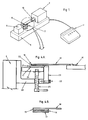
- Figure 1 is a schematic view of a testing apparatus of this invention.
- Figure 2 is a plan view of the apparatus and
- Figure 3 is a side view of Figure 2 and
- Figure 4A is a detailed view of the clamp as shown in Figure 3 and
- Figure 4B is a side view of the prepared sample.
- the apparatus comprises a body section 5 mounted on which is a load cell 6 secured to which is clamp means 7 and mounted at the other end is the force applying device 9 secured to which is the projecting tongue 10.
- the sample 8 is held between the clamp 7 and projecting tongue 10.
- the controller 11 incorporates a microprocessor and is programmed to provide:
- the sample 8 best seen in Figure 4B comprises the topliner 15, the medium 16 and the bottom liner 17.
- Liner 15 is bonded preferably by double sided tape to a plastic strip 18.
- a hole in plastic strip 18 clips into place over the projecting lug on the tongue 10.
- the clamp 7 best seen in Figure 4A comprises a body section 20, a set of prongs 21 which lie on medium 16. These prongs 21 are secured to body section 20 by the screws 22. Plate 24 abuts the outerface of liner 17 so that liner 17 and medium 16 are held between plate 24 and prongs 21. Plate 24 is supported on screw jack 25 which is mounted for threaded movement in body section 20. The screw jack 25 with associated spring 26 ensures the plate 24 is strongly loaded against liner 17.
- the abutment plate 23 which is part of the body section 20 of clamp 7 is arranged around prongs 21 to prevent any movement of the medium 16 and bottom liner 17.
- clamp 7 not only avoids tearing of the sample but also enables better sample alignment so that shear force is applied parallel to the flutes and the adhesion lines between the medium and the liner.
- the apparatus and sample holder provide a simple and effective means of measuring the wet strength of adhesive bonds in corrugated boards.
Landscapes
- Health & Medical Sciences (AREA)
- Life Sciences & Earth Sciences (AREA)
- Chemical & Material Sciences (AREA)
- Pathology (AREA)
- Physics & Mathematics (AREA)
- Analytical Chemistry (AREA)
- Biochemistry (AREA)
- General Health & Medical Sciences (AREA)
- General Physics & Mathematics (AREA)
- Immunology (AREA)
- Food Science & Technology (AREA)
- Medicinal Chemistry (AREA)
- Engineering & Computer Science (AREA)
- Investigating Strength Of Materials By Application Of Mechanical Stress (AREA)
- Paper (AREA)
- Spinning Methods And Devices For Manufacturing Artificial Fibers (AREA)
- Adhesives Or Adhesive Processes (AREA)
- Reinforced Plastic Materials (AREA)
- Holo Graphy (AREA)
- Dry Shavers And Clippers (AREA)
- Glass Compositions (AREA)
- Testing Of Individual Semiconductor Devices (AREA)
- Diaphragms For Electromechanical Transducers (AREA)
- Testing Electric Properties And Detecting Electric Faults (AREA)
Abstract
Description
- This invention relates to methods of failure testing of materials and in particular corrugated paper board.
- One particular aspect of corrugated board quality control is the quality of the adhesive bond between the lines and the medium, particularly its resistance to water.
- Three test methods have been used.
- The standard test is a subjective test of immersion of a sample in water then manual peeling of the liners from the medium and a visual assessment of fibre tear. Absence of fibre tear indicates poor adhesive resistance to water damage.
- The FEFCO method No. 9 involves the immersion of a piece of board in water with a specified number of glue bonds subjected to the load imposed by a hanging weight (either 250 or 350g). The number of hours the bond can withstand the load is measured.
- Another more objective method is described in Australian Patent 581511. That patent discloses a technique of preparing a sample of corrugated board by isolating a portion of the outer liner by removing part of the liner to isolate one piece attached to the medium. A hole or eyelet is prepared in the other portion of the board and a plastic strip is hot melt bonded to the portion of liner to be tested.
- Hooks are placed in a hole in the plastic strip and the board. The testing apparatus comprises a beam balance with a water collecter on one beam and the sample on the other. The plastic strip is connected to the balance beam while the paperboard sample is secured to the stand. Water is added progressively to the collecter until the wet sample fails and the liner is displaced from the medium. This method aims to apply a constantly increasing force parallel to the glue lines of the sample.
- Whilst this test was the first method to produce quantitative results, a number of difficulties exist with this method. The apparatus is clumsy and difficult to control and must be attended by an operator. Sample preparation is tedious and must be carefully done to avoid damage to the medium. The wet sample also tends to tear at the hole in the second portion. Further, if the glue bond of the side to be tested is appreciably stronger than the glue bond in the other side of the sample, then failure occurs on the weaker side rather than on the side to be tested.
- It is an object of this invention to overcome these problems.
- The present invention provides a clamp which enables one liner to medium glue bond to be tested whilst firmly securing the medium and other liner. This method specifically loads the glue bond under test and avoids the problem of the sample merely failing at its weakest point.
- In particular this invention provides apparatus for measuring the strength of the adhesive bond between a corrugated paperboard medium (16) and a paperboard liner, said apparatus comprising a load measuring device, a load applying device and means for clamping a corrugated paperboard sample between said load measuring device and said load applying device, said apparatus being characterised in that said sample is prepared by bonding a rigid strip to said liner, said load applying device being adapted to apply a force to said strip in a direction parallel to the adhesive bond between said corrugated medium and said liner and gripping means connected to said load measuring device, said gripping means comprising a plate and a plurality of prongs adapted to be within the flutes of said corrugated medium so that said gripping means grips the corrugated medium.
- A sample of board to be tested is carefully cut and the liner adjacent to the glue bond under test is bonded to a plastic strip.
- The liner and medium on the opposite side to the glue bond to be tested are securely fixed to the test instrument by a clamping arrangement. The preferred form of clamp comprises a body section projecting from which is a series of prongs adapted to fit within the flutes of the corrugated medium at the appropriate flute pitch and a backing plate loaded against the other face of the liner, and such backing plate is connected to said body section. The backing plate is adjustable to clamp the liner and the glue bond not under test between the prongs and the backing plate.
- The plastic strip is then secured to a projecting tongue in the test instrument. This strip is preferably connected to the load applying device while the gripping device for the medium is connected to a load cell as part of the load measuring device.
- This arrangement means that a small sample is cut from the board to be tested and no further preparation is required. The sample is effectively tensioned by means of securely holding one liner and the medium bonded to it and applying a shearing force to the other liner.
- Another aspect of this invention provides a testing apparatus comprising:
- 1) a load cell attached to which a sample clamp as described above opposed to which is;
- 2) a second sample clamp secured to a means for applying a progressively increasing force to the glue bond under the test via the plastic strip. The preferred embodiment of this is a projecting lug or other clamping arrangement which attaches to the plastic strip;
- 3) a controller for controlling the force applied to the sample by said means; and
- 4) a measuring and display device for measuring the force at which displacement and sample failure occur and displaying it.
- A preferred form of this invention will now be described in which Figure 1 is a schematic view of a testing apparatus of this invention. Figure 2 is a plan view of the apparatus and Figure 3 is a side view of Figure 2 and Figure 4A is a detailed view of the clamp as shown in Figure 3 and Figure 4B is a side view of the prepared sample.
- The apparatus comprises a
body section 5 mounted on which is aload cell 6 secured to which is clamp means 7 and mounted at the other end is theforce applying device 9 secured to which is the projectingtongue 10. - The sample 8 is held between the
clamp 7 and projectingtongue 10. Thecontroller 11 incorporates a microprocessor and is programmed to provide: - (i) force measurement and control;
- (ii) failure detection of sample;
- (iii) shear rate input;
- (iv) display functions;
- (v) a calibration routine;
- (vi) statistical processing of results.
- The sample 8 best seen in Figure 4B comprises the
topliner 15, themedium 16 and thebottom liner 17.Liner 15 is bonded preferably by double sided tape to aplastic strip 18. A hole inplastic strip 18 clips into place over the projecting lug on thetongue 10. - The
clamp 7 best seen in Figure 4A comprises abody section 20, a set ofprongs 21 which lie onmedium 16. Theseprongs 21 are secured tobody section 20 by thescrews 22.Plate 24 abuts the outerface ofliner 17 so thatliner 17 andmedium 16 are held betweenplate 24 and prongs 21.Plate 24 is supported onscrew jack 25 which is mounted for threaded movement inbody section 20. Thescrew jack 25 with associated spring 26 ensures theplate 24 is strongly loaded againstliner 17. Theabutment plate 23 which is part of thebody section 20 ofclamp 7 is arranged aroundprongs 21 to prevent any movement of themedium 16 andbottom liner 17. - The avoidance of hooks by using
clamp 7 not only avoids tearing of the sample but also enables better sample alignment so that shear force is applied parallel to the flutes and the adhesion lines between the medium and the liner. - From the above it can be seen that the apparatus and sample holder provide a simple and effective means of measuring the wet strength of adhesive bonds in corrugated boards.
Claims (1)
- Apparatus for measuring the strength of the adhesive bond between a corrugated paperboard medium (16) and a paperboard liner (15), said apparatus comprising a load measuring device, a load applying device (9) and means (7) for clamping a corrugated paperboard sample between said load measuring device and said load applying device, said apparatus being characterised in that said sample is prepared by bonding a rigid strip (18) to said liner (15), said load applying device (9) being adapted to apply a force to said strip in a direction parallel to the adhesive bond between said corrugated medium and said liner and gripping means connected to said load measuring device, said gripping means comprising a plate (24) and a plurality of prongs (21) adapted to be within the flutes of said corrugated medium so that said gripping means grips the corrugated medium.
Priority Applications (1)
| Application Number | Priority Date | Filing Date | Title |
|---|---|---|---|
| AT89306267T ATE104054T1 (en) | 1988-06-23 | 1989-06-21 | TEST DEVICE. |
Applications Claiming Priority (2)
| Application Number | Priority Date | Filing Date | Title |
|---|---|---|---|
| AUPI894188 | 1988-06-23 | ||
| AU8941/88 | 1988-06-23 |
Publications (3)
| Publication Number | Publication Date |
|---|---|
| EP0348177A2 EP0348177A2 (en) | 1989-12-27 |
| EP0348177A3 EP0348177A3 (en) | 1991-02-20 |
| EP0348177B1 true EP0348177B1 (en) | 1994-04-06 |
Family
ID=3773178
Family Applications (1)
| Application Number | Title | Priority Date | Filing Date |
|---|---|---|---|
| EP89306267A Expired - Lifetime EP0348177B1 (en) | 1988-06-23 | 1989-06-21 | Testing apparatus |
Country Status (9)
| Country | Link |
|---|---|
| US (1) | US4957004A (en) |
| EP (1) | EP0348177B1 (en) |
| AT (1) | ATE104054T1 (en) |
| DE (1) | DE68914341T2 (en) |
| DK (2) | DK171861B1 (en) |
| ES (1) | ES2050803T3 (en) |
| FI (1) | FI96992C (en) |
| NO (1) | NO179267C (en) |
| NZ (1) | NZ229646A (en) |
Families Citing this family (20)
| Publication number | Priority date | Publication date | Assignee | Title |
|---|---|---|---|---|
| DE4009081A1 (en) * | 1990-03-21 | 1991-10-10 | Madaus Ag | TEST DEVICE |
| US5176028A (en) * | 1990-10-01 | 1993-01-05 | The State Of Oregon Acting By And Through The Oregon State Board Of Higher Education On Behalf Of Oregon State University | Device for testing adhesive bonds |
| US5111701A (en) * | 1991-05-03 | 1992-05-12 | Klein Gregory N | Container corner section glue bond tester |
| US5404751A (en) * | 1994-07-29 | 1995-04-11 | Westvaco Corporation | Method and apparatus for measuring the peel strength of an adhesively bonded paper joint |
| AUPN260495A0 (en) * | 1995-04-24 | 1995-05-18 | Amcor Limited | Method and apparatus of testing board product |
| US5705752A (en) * | 1996-03-01 | 1998-01-06 | The Aerospace Corporation | Rubber substrate shear lap-joint testing fixture and method |
| RU2173845C2 (en) * | 1997-02-06 | 2001-09-20 | Акционерное общество открытого типа Башкирское специальное конструкторское бюро "Нефтехимавтоматика" | Instrument for determination of ultimate strength, thermo-and moisture- reinforcement of plastic lubricants |
| US5767414A (en) * | 1997-03-05 | 1998-06-16 | Mitsubishi Semiconductor America, Inc. | Automatically aligning tool for uniformly applying a controlled force to an object |
| SE513007C2 (en) * | 1998-02-25 | 2000-06-19 | Lorentzen & Wettre Ab | Method and apparatus for measuring the tensile strength of paper or paperboard in the z-direction |
| US5961766A (en) * | 1998-04-17 | 1999-10-05 | Avery Dennison Corporation | Method for selecting a substrate intended for use in a cutting operation |
| US20040050152A1 (en) * | 2002-09-12 | 2004-03-18 | King Rex M. | Apparatus for measuring adhesion of gelled polymers |
| US20040103726A1 (en) * | 2002-12-02 | 2004-06-03 | Malcolm Cox | Bond test systems with offset shear tool |
| US6802214B2 (en) * | 2003-02-11 | 2004-10-12 | National Starch And Chemical Investment Holding Corporation | Envelope quality control apparatus |
| US20090272185A1 (en) * | 2008-05-01 | 2009-11-05 | Tung Yuan Tsaur | Material adhesion performance tester |
| US8286499B2 (en) | 2008-07-19 | 2012-10-16 | The Boeing Company | Method and apparatus for testing attachment joints |
| US8043449B1 (en) | 2009-06-06 | 2011-10-25 | The Boeing Company | Apparatus and method for fabricating shear test coupons |
| CN102243164A (en) * | 2010-05-11 | 2011-11-16 | 鸿富锦精密工业(深圳)有限公司 | Testing device of adhesive tape viscous force |
| CN103737516B (en) * | 2013-12-25 | 2015-07-08 | 上海纳米技术及应用国家工程研究中心有限公司 | Microtensile Bond Strength Test Fixture for Dental Adhesives |
| CN105181584A (en) * | 2015-09-23 | 2015-12-23 | 合肥国轩高科动力能源有限公司 | Device for qualitatively testing adhesion performance of battery pole piece |
| CN106525572A (en) * | 2016-12-09 | 2017-03-22 | 张家港市利奇塑料有限公司 | Self-adhesive test fixture |
Family Cites Families (6)
| Publication number | Priority date | Publication date | Assignee | Title |
|---|---|---|---|---|
| US1298138A (en) * | 1918-05-17 | 1919-03-25 | George S Witham Jr | Paper-tester. |
| US2637996A (en) * | 1948-09-09 | 1953-05-12 | Paper Chemistry Inst | Method and apparatus for testing paperboard |
| US2982129A (en) * | 1954-11-12 | 1961-05-02 | Minnesota Mining & Mfg | Method for testing gummed tape |
| US3678738A (en) * | 1970-08-06 | 1972-07-25 | Gen Motors Corp | Test device for trim assemblies |
| US4297144A (en) * | 1975-07-22 | 1981-10-27 | Cpc International Inc. | High speed corrugating adhesives |
| US4380174A (en) * | 1980-08-15 | 1983-04-19 | Tanenbaum Joseph M | Apparatus for shear testing welds |
-
1989
- 1989-06-19 US US07/367,808 patent/US4957004A/en not_active Expired - Lifetime
- 1989-06-21 DK DK306989A patent/DK171861B1/en not_active IP Right Cessation
- 1989-06-21 EP EP89306267A patent/EP0348177B1/en not_active Expired - Lifetime
- 1989-06-21 NZ NZ229646A patent/NZ229646A/en unknown
- 1989-06-21 DE DE68914341T patent/DE68914341T2/en not_active Expired - Fee Related
- 1989-06-21 FI FI893050A patent/FI96992C/en not_active IP Right Cessation
- 1989-06-21 DK DK306989D patent/DK306989A/en unknown
- 1989-06-21 ES ES89306267T patent/ES2050803T3/en not_active Expired - Lifetime
- 1989-06-21 AT AT89306267T patent/ATE104054T1/en not_active IP Right Cessation
- 1989-06-22 NO NO892600A patent/NO179267C/en unknown
Also Published As
| Publication number | Publication date |
|---|---|
| FI893050L (en) | 1989-12-24 |
| NO892600D0 (en) | 1989-06-22 |
| FI96992C (en) | 1996-09-25 |
| DK171861B1 (en) | 1997-07-14 |
| DK306989D0 (en) | 1989-06-21 |
| FI96992B (en) | 1996-06-14 |
| DE68914341T2 (en) | 1994-07-28 |
| EP0348177A3 (en) | 1991-02-20 |
| NZ229646A (en) | 1990-12-21 |
| US4957004A (en) | 1990-09-18 |
| DE68914341D1 (en) | 1994-05-11 |
| ATE104054T1 (en) | 1994-04-15 |
| DK306989A (en) | 1989-12-24 |
| EP0348177A2 (en) | 1989-12-27 |
| FI893050A0 (en) | 1989-06-21 |
| NO179267B (en) | 1996-05-28 |
| NO892600L (en) | 1989-12-27 |
| NO179267C (en) | 1996-09-04 |
| ES2050803T3 (en) | 1994-06-01 |
Similar Documents
| Publication | Publication Date | Title |
|---|---|---|
| US4957004A (en) | Testing apparatus | |
| JP7204358B2 (en) | Adhesion test system and method | |
| CA1104372A (en) | Material testing device with solenoid-applied test force | |
| US6026680A (en) | Paint and adhesive test system | |
| US2752780A (en) | Apparatus for testing adhesive tape | |
| US6976396B2 (en) | Loading device for non-destructive inspections of composite structures | |
| AU608450B2 (en) | Testing apparatus | |
| CN211905048U (en) | Peeling strength testing machine for yeast recombinant collagen dressing | |
| CN216978782U (en) | Structure for testing tearing cover tape force of plastic package of cover tape on frame | |
| CN220751938U (en) | Device for measuring peel strength | |
| RU2390004C1 (en) | Method of assessing bonding strength between screen-printing inks and coatings with print media | |
| CN223711378U (en) | Viscosity test fixture suitable for pjncture needle adjustment support | |
| CN113588551A (en) | Device and method for testing drawing strength of binder for bridge deck pavement | |
| CN223435838U (en) | A 90-degree peeling auxiliary tool | |
| SU974225A1 (en) | Device for determination of joint component adhesion bond strength | |
| CN223926256U (en) | Device for measuring binding force between backlight and LCD | |
| Christ | Effect of specimen preparation, setup, and test procedures on test results | |
| JPH02236142A (en) | Adhesion strength measuring apparatus | |
| Temme | Investigations Into the Adhesion, Strength and Aging Behavior of Plastic-to-Plastic Adhesive Bonded Joints | |
| DE20014891U1 (en) | Measuring device for determining the viscoelastic properties of PSAs, especially in thin layers | |
| CN106525572A (en) | Self-adhesive test fixture | |
| DE10042289A1 (en) | Measurement of viscoelastic properties of pressure-sensitive adhesives, especially for medical and technical adhesive tapes, comprises subjecting sample of adhesive to constant shear stress and determining shear produced over time | |
| CN119666735A (en) | A release film peeling force testing device | |
| Sosnitskii et al. | RIG FOR RECORDING TENSILE TEST DIAGRAMS OF THIN FOILS | |
| EP0826149B1 (en) | Method and apparatus of testing board product |
Legal Events
| Date | Code | Title | Description |
|---|---|---|---|
| PUAI | Public reference made under article 153(3) epc to a published international application that has entered the european phase |
Free format text: ORIGINAL CODE: 0009012 |
|
| AK | Designated contracting states |
Kind code of ref document: A2 Designated state(s): AT BE CH DE ES FR GB GR IT LI LU NL SE |
|
| PUAL | Search report despatched |
Free format text: ORIGINAL CODE: 0009013 |
|
| AK | Designated contracting states |
Kind code of ref document: A3 Designated state(s): AT BE CH DE ES FR GB GR IT LI LU NL SE |
|
| RHK1 | Main classification (correction) |
Ipc: G01N 19/04 |
|
| 17P | Request for examination filed |
Effective date: 19910621 |
|
| 17Q | First examination report despatched |
Effective date: 19930115 |
|
| RAP1 | Party data changed (applicant data changed or rights of an application transferred) |
Owner name: AMCOR LIMITED |
|
| GRAA | (expected) grant |
Free format text: ORIGINAL CODE: 0009210 |
|
| ITF | It: translation for a ep patent filed | ||
| AK | Designated contracting states |
Kind code of ref document: B1 Designated state(s): AT BE CH DE ES FR GB GR IT LI LU NL SE |
|
| REF | Corresponds to: |
Ref document number: 104054 Country of ref document: AT Date of ref document: 19940415 Kind code of ref document: T |
|
| REF | Corresponds to: |
Ref document number: 68914341 Country of ref document: DE Date of ref document: 19940511 |
|
| ET | Fr: translation filed | ||
| REG | Reference to a national code |
Ref country code: ES Ref legal event code: FG2A Ref document number: 2050803 Country of ref document: ES Kind code of ref document: T3 |
|
| PG25 | Lapsed in a contracting state [announced via postgrant information from national office to epo] |
Ref country code: LU Free format text: LAPSE BECAUSE OF NON-PAYMENT OF DUE FEES Effective date: 19940630 |
|
| REG | Reference to a national code |
Ref country code: GR Ref legal event code: FG4A Free format text: 3012217 |
|
| EAL | Se: european patent in force in sweden |
Ref document number: 89306267.9 |
|
| PLBE | No opposition filed within time limit |
Free format text: ORIGINAL CODE: 0009261 |
|
| STAA | Information on the status of an ep patent application or granted ep patent |
Free format text: STATUS: NO OPPOSITION FILED WITHIN TIME LIMIT |
|
| 26N | No opposition filed | ||
| REG | Reference to a national code |
Ref country code: GB Ref legal event code: IF02 |
|
| PGFP | Annual fee paid to national office [announced via postgrant information from national office to epo] |
Ref country code: GR Payment date: 20050524 Year of fee payment: 17 |
|
| PGFP | Annual fee paid to national office [announced via postgrant information from national office to epo] |
Ref country code: NL Payment date: 20050605 Year of fee payment: 17 |
|
| PGFP | Annual fee paid to national office [announced via postgrant information from national office to epo] |
Ref country code: SE Payment date: 20050607 Year of fee payment: 17 |
|
| PGFP | Annual fee paid to national office [announced via postgrant information from national office to epo] |
Ref country code: FR Payment date: 20050608 Year of fee payment: 17 |
|
| PGFP | Annual fee paid to national office [announced via postgrant information from national office to epo] |
Ref country code: AT Payment date: 20050613 Year of fee payment: 17 |
|
| PGFP | Annual fee paid to national office [announced via postgrant information from national office to epo] |
Ref country code: GB Payment date: 20050615 Year of fee payment: 17 |
|
| PGFP | Annual fee paid to national office [announced via postgrant information from national office to epo] |
Ref country code: DE Payment date: 20050616 Year of fee payment: 17 |
|
| PGFP | Annual fee paid to national office [announced via postgrant information from national office to epo] |
Ref country code: CH Payment date: 20050629 Year of fee payment: 17 |
|
| PGFP | Annual fee paid to national office [announced via postgrant information from national office to epo] |
Ref country code: ES Payment date: 20050728 Year of fee payment: 17 |
|
| PGFP | Annual fee paid to national office [announced via postgrant information from national office to epo] |
Ref country code: BE Payment date: 20050817 Year of fee payment: 17 |
|
| PG25 | Lapsed in a contracting state [announced via postgrant information from national office to epo] |
Ref country code: GB Free format text: LAPSE BECAUSE OF NON-PAYMENT OF DUE FEES Effective date: 20060621 Ref country code: AT Free format text: LAPSE BECAUSE OF NON-PAYMENT OF DUE FEES Effective date: 20060621 |
|
| PG25 | Lapsed in a contracting state [announced via postgrant information from national office to epo] |
Ref country code: SE Free format text: LAPSE BECAUSE OF NON-PAYMENT OF DUE FEES Effective date: 20060622 Ref country code: ES Free format text: LAPSE BECAUSE OF NON-PAYMENT OF DUE FEES Effective date: 20060622 |
|
| PG25 | Lapsed in a contracting state [announced via postgrant information from national office to epo] |
Ref country code: LI Free format text: LAPSE BECAUSE OF NON-PAYMENT OF DUE FEES Effective date: 20060630 Ref country code: CH Free format text: LAPSE BECAUSE OF NON-PAYMENT OF DUE FEES Effective date: 20060630 Ref country code: BE Free format text: LAPSE BECAUSE OF NON-PAYMENT OF DUE FEES Effective date: 20060630 |
|
| PGFP | Annual fee paid to national office [announced via postgrant information from national office to epo] |
Ref country code: IT Payment date: 20060630 Year of fee payment: 18 |
|
| PG25 | Lapsed in a contracting state [announced via postgrant information from national office to epo] |
Ref country code: NL Free format text: LAPSE BECAUSE OF NON-PAYMENT OF DUE FEES Effective date: 20070101 |
|
| PG25 | Lapsed in a contracting state [announced via postgrant information from national office to epo] |
Ref country code: DE Free format text: LAPSE BECAUSE OF NON-PAYMENT OF DUE FEES Effective date: 20070103 |
|
| REG | Reference to a national code |
Ref country code: CH Ref legal event code: PL |
|
| EUG | Se: european patent has lapsed | ||
| GBPC | Gb: european patent ceased through non-payment of renewal fee |
Effective date: 20060621 |
|
| NLV4 | Nl: lapsed or anulled due to non-payment of the annual fee |
Effective date: 20070101 |
|
| REG | Reference to a national code |
Ref country code: FR Ref legal event code: ST Effective date: 20070228 |
|
| REG | Reference to a national code |
Ref country code: ES Ref legal event code: FD2A Effective date: 20060622 |
|
| BERE | Be: lapsed |
Owner name: *AMCOR LTD Effective date: 20060630 |
|
| PG25 | Lapsed in a contracting state [announced via postgrant information from national office to epo] |
Ref country code: FR Free format text: LAPSE BECAUSE OF NON-PAYMENT OF DUE FEES Effective date: 20060630 |
|
| PG25 | Lapsed in a contracting state [announced via postgrant information from national office to epo] |
Ref country code: GR Free format text: LAPSE BECAUSE OF NON-PAYMENT OF DUE FEES Effective date: 20070104 |
|
| PG25 | Lapsed in a contracting state [announced via postgrant information from national office to epo] |
Ref country code: IT Free format text: LAPSE BECAUSE OF NON-PAYMENT OF DUE FEES Effective date: 20070621 |