EP0348095B1 - Non-interfering method for measuring propagation delay of telecommunications network and apparatus for accomplishing same - Google Patents
Non-interfering method for measuring propagation delay of telecommunications network and apparatus for accomplishing same Download PDFInfo
- Publication number
- EP0348095B1 EP0348095B1 EP89306019A EP89306019A EP0348095B1 EP 0348095 B1 EP0348095 B1 EP 0348095B1 EP 89306019 A EP89306019 A EP 89306019A EP 89306019 A EP89306019 A EP 89306019A EP 0348095 B1 EP0348095 B1 EP 0348095B1
- Authority
- EP
- European Patent Office
- Prior art keywords
- propagation delay
- delay
- communication line
- communicating means
- milliseconds
- Prior art date
- Legal status (The legal status is an assumption and is not a legal conclusion. Google has not performed a legal analysis and makes no representation as to the accuracy of the status listed.)
- Expired - Lifetime
Links
Images


Classifications
-
- H—ELECTRICITY
- H04—ELECTRIC COMMUNICATION TECHNIQUE
- H04B—TRANSMISSION
- H04B3/00—Line transmission systems
- H04B3/02—Details
- H04B3/46—Monitoring; Testing
- H04B3/462—Testing group delay or phase shift, e.g. timing jitter
-
- H—ELECTRICITY
- H04—ELECTRIC COMMUNICATION TECHNIQUE
- H04J—MULTIPLEX COMMUNICATION
- H04J3/00—Time-division multiplex systems
- H04J3/02—Details
- H04J3/06—Synchronising arrangements
- H04J3/0635—Clock or time synchronisation in a network
- H04J3/0682—Clock or time synchronisation in a network by delay compensation, e.g. by compensation of propagation delay or variations thereof, by ranging
Definitions
- This invention generally relates to methods and apparatus for measuring the propagation delay of a telecommunications network. More particularly, this invention relates to non-interfering methods and apparatus for measuring propagation delay between communicating devices by using the edge of the data communications passband for sending and receiving signals meant for the measurement of propagation delay.
- EP-A-0242142 discusses an alternative in which time slots of a transmission frame of a multiplexed system are used for sending and looping back test signals so that transmission delay can be measured: these time slots could otherwise be allocated for the transmission of data in both directions.
- a method for measuring the propagation delay of a data communication line connecting first and second communicating means comprising transmitting a known signal in conjunction with a primary data frequency spectrum over said data communication line from said first communicating means to said second communicating means, looping said known signal back from said second communicating means to said first communicating means, detecting receipt of said known signal at said first communicating means and determining a loop time between transmitting said known signal from and receiving said known signal back at said first communicating means, said method being characterised by transmitting said known signal at a frequency not interfering with primary data frequency spectrum, by finding a delay distortion time for said communication line and by determining propagation delay from said determined loop time and said delay distortion time.
- apparatus for measuring the propagation delay of a data communication line connecting first and second communicating means, said first communicating means including means for generating and transmitting a known signal in conjunction with a primary data frequency spectrum over said data communication line from said first communicating means to said second communicating means, means for detecting receipt of said known signal when looped back by said second communicating means to said first communicating means, clocking means coupled to said detecting means and to said generating and transmitting means for timing said transmission of said known signal and said receipt of said known signal and for determining a loop time between said transmitting and said receipt of said known signal, and said second communicating means having the capability of looping data received over said data communication line back to said first communicating means, said apparatus being characterised in that said generating and transmitting means is arranged to transmit said known signal at a frequency not interfering with said primary data frequency spectrum, and in that said apparatus further comprises means coupled to said clocking means for finding a delay distortion time for said communication line based on at least said determined loop time, and processing means for determining propagation delay
- the propagation delay for a particular secondary channel frequency is preferably determined by subtracting a correction factor from the round trip delay (loop time minus known fixed delays).
- round trip or one way delay distortion may be determined from a look-up table which relates distance ranges to distortion delay relative to a middle frequency.
- An approximate distance between the communicating means from which a distance range is chosen is obtained from the difference of the measured loop time and the known fixed delays of the communicating means.
- the propagation delay is then determined by subtracting the known fixed delays and the round trip delay distortion time from the determined loop time, and dividing by two.
- a source unit transmits over a secondary (diagnostic) channel of a line a known signal (typically a "space" comprised of all zeros or all ones) to a target unit.
- the target is arranged to loop back at 25a the known signal to the source, thereby establishing the integrity of the loop.
- the source sends a known data pattern signal (e.g. reversals with data changing states at known intervals) over the secondary channel.
- the source With the target looping back at 35a the data pattern signal, the source will at 40 ⁇ a be able to receive back the pattern and record the instants in time that the changes in the state took place. Knowing the time at which each change in state of the data was transmitted, a determination of the average total signal propagation delay (hereinafter referred to as the " loop time”) may be calculated at 50 ⁇ a.
- the communication of the known data pattern signal is preferably conducted over a secondary channel (i.e. at a frequency at the edge of the passband) of the line.
- a secondary channel i.e. at a frequency at the edge of the passband
- extra delay is encountered which will not be found in communications occurring over the midband frequencies of the unconditioned line.
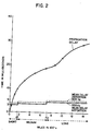
- Figure 2 which was compiled from information set forth in the End Office Connection Survey Bell System Technical Journal, November 1984 (pages 20 ⁇ 78-20 ⁇ 87), this extra delay is a function both of the frequency of the secondary channel frequency as well as the distance between the communicating source and target.
- the mean envelope delay distortion of a 330 ⁇ Hz signal relative to a middle band frequency of approximately 170 ⁇ 0 ⁇ Hz is approximately 3 milliseconds.
- the mean envelope delay for the 330 ⁇ Hz signal is approximately 3.5 milliseconds, while for long connections (>1160 ⁇ kilometres-720 ⁇ miles), the mean envelope delay is approximately 4.5 milliseconds.
- the mean envelope delay relative to the middle band frequency of 170 ⁇ 0 ⁇ Hz will be different.
- the mean envelope delays for short, medium and long connections are 3.6, 4.3 and 5.0 ⁇ milliseconds respectively.
- the mean envelope delays set forth in Figure 2 are shown as step functions depending on the group into which the line distance falls (i.e. short, middle or long). However, if desired, additional groups of distances could be added and more points plotted on Figure 2. Indeed, a curve of mean envelope delay versus line distance could be determined for any particular secondary channel frequency used.
- a preliminary determination of line distance must be had before a determination of envelope distortion delay may be determined.
- the known fixed delay of the communicating means is subtracted from the loop time found at 50 ⁇ a.
- the loop time minus the fixed delays provides a rough estimate of the line distance as a rough relationship of loop time to line distance exists.
- the envelope delay (or "delay distortion time") is determined at 60 ⁇ preferably using either a look-up table, or Figure 2. Then, with the determinations of delay distortion time and loop time minus fixed delay having been made at 60 ⁇ and 53a respectively, a determination of propagation delay may be had at 70 ⁇ a.
- the propagation delay is determined by subtracting the round trip delay distortion time determined at 60 ⁇ from the difference of the loop time and fixed delays determined at 53a.
- Steps 20 ⁇ b, 30 ⁇ b, 35b, 40 ⁇ b, 50 ⁇ b, and 53b all correspond to the previously described steps 20 ⁇ a, 25a, 30 ⁇ a, 40 ⁇ a, 50 ⁇ a, and 53b such that at 53b, a determination of the loop time minus the fixed delays is made.
- the propagation delay is determined directly in Figure 1b at step 70 ⁇ b.
- the propagation delay is found by taking the loop time minus the fixed delays of the communicating means, and depending upon the value, choosing and subtracting a round trip delay distortion value.
- a delay distortion of six milliseconds is chosen and subtracted from the adjusted loop time to provide the determined propagation delay (which is not less than zero).
- a delay distortion of seven milliseconds is chosen and subtracted to provide the propagation delay.
- nine milliseconds is chosen as the delay distortion and is subtracted to provide the propagation delay.
- the propagation delay of a line may be monitored over time by repeating the method steps set forth in Figures 1a or 1b.
- steps 20 ⁇ and 25 need not be repeated. The repetition of the propagation delay measurement would provide the user with an indication as to whether a communication is being rerouted during transmission.
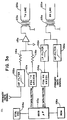
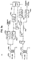
- FIGS. 3a and 3b where like numerals are indicative of like parts, the means for conducting the steps of Figures 1a and 1b are broadly shown and basically comprise front ends 10 ⁇ 0 ⁇ a and 10 ⁇ 0 ⁇ b to modems (not shown). While front ends 10 ⁇ 0 ⁇ a and 10 ⁇ 0 ⁇ b are not identical as shown , those skilled in the art will appreciate that it might be beneficial for all modems to incorporate the features of both the master and slave modems.
- primary data which has been modulated by a modem is high pass filtered at 10 ⁇ 2a to clear the sidebands which would fall into the 30 ⁇ 0 ⁇ -40 ⁇ 0 ⁇ Hz range of the secondary channel.
- a microprocessor 110 ⁇ a such as a Motorola 680 ⁇ 9, having an associated timing source 10 ⁇ 4a and ROM 10 ⁇ 6a is provided and arranged to send data patterns (signals) as discussed with reference to Figures 1a and 1b.
- the data signals are then converted to FSK signals at the desired frequencies by an FSK signal generator 112a such as an XR220 ⁇ 6 manufactured by Exar Corp.
- the primary data signal and the secondary FSK data signal are summed by a summing amplifier 115a and resistors 116a and 118a.
- the resultant composite signal is then transmitted over the data communication line 120 ⁇ a via transformer 122a.
- the front end 10 ⁇ 0 ⁇ b of the looping modem receives the composite transmitted signal at transformer 125b.
- the composite transmitted signal is then split.
- One path is high pass filtered at 130 ⁇ b to provide the primary data signals, and the other path is low pass filtered at 132b to provide the secondary data signal.
- the FSK secondary data signal is then demodulated via a phase locked loop circuit 134b such as an XR2211 manufactured by Exar Corp.
- the resultant digital data is then received by microprocessor 110 ⁇ b.
- microprocessor 110 ⁇ b will have set loopback switch 140 ⁇ (together with gain adjustment as required) to accomplish the same, and will have set switch 141 to cut off any secondary signals being received from the FSK transmit 112b.
- the secondary signals originally forwarded from modem front end 10 ⁇ 0 ⁇ a will be looped back via resistor 118b, and summed by summing amplifier 115b together with primary signals which have been high pass filtered at 10 ⁇ 2b to filter out sidebands which would fall in the secondary channel frequency range.
- the composite signal is then transmitted via transformer 122b, and line 120 ⁇ b back to the front end 10 ⁇ 0 ⁇ a of the transmitting modem.
- the composite primary and secondary signal is received by transformer 125a and again split.
- One path is high pass filtered at 130 ⁇ a to provide the primary signal while the other is low pass filtered at 132a to provide the secondary channel signal which is demodulated by the phase lock loop 134a and sent to microprocessor 10 ⁇ 0 ⁇ a.
- the receipt of the signal stops a counter in microprocessor 10 ⁇ 0 ⁇ a, which, with the help of oscillator 10 ⁇ 4a, had been timing the loop time between the sending and receipt of the same.
- the microprocessor 110 ⁇ a with the use of ROM 10 ⁇ 6a which preferably stores at least look-up tables regarding delay distortion time, may then conduct the necessary calculations for a determination of propagation delay.
- non-interfering average frequency of 330 ⁇ Hz was chosen as the preferred frequency for conducting the measurement, it will be appreciated that other frequencies could be chosen, provided the delay distortion time is taken into account for the chosen frequency when making the propagation delay determination.
- the choice of means for finding the delay distortion times could vary from loop-up charts or tables, to dedicated circuitry depending on the loop time or loop time minus fixed communication means delays, to graphs, and to other available means in the art.
- the provided circuitry for conducting the propagation delay measurement could easily be changed to various equivalents as would be known to those skilled in the art.
Landscapes
- Engineering & Computer Science (AREA)
- Computer Networks & Wireless Communication (AREA)
- Signal Processing (AREA)
- Monitoring And Testing Of Transmission In General (AREA)
Description
- This invention generally relates to methods and apparatus for measuring the propagation delay of a telecommunications network. More particularly, this invention relates to non-interfering methods and apparatus for measuring propagation delay between communicating devices by using the edge of the data communications passband for sending and receiving signals meant for the measurement of propagation delay.
- Data communication between two points theoretically can be conducted at the speed of light. However, due to delays inherent in the communicating devices themselves as well as delays in the intermediate transmitting stations, telecommunications are slowed down. Also, because of the ability of the telephone companies to route communications in many different ways due to local or regional congestion, communication between two points may take a roundabout route. Roundabout routes, however, offer inferior performances compared to more direct routes because of both increased noise and the delay itself. Thus, a good measurement of propagation delay could be beneficial in determining the source of inferior performance.
Presently, one technique for measuring propagation delay of communications between two devices connected by a transmission line requires that the data communications on the line be interrupted so that a test of the line can be carried out. Because of the inconvenience of such interruptions, propagation delay is rarely measured in this manner. EP-A-0242142 discusses an alternative in which time slots of a transmission frame of a multiplexed system are used for sending and looping back test signals so that transmission delay can be measured: these time slots could otherwise be allocated for the transmission of data in both directions. - It is therefore an object of the invention to provide a method for determining the propagation delay between devices communicating over transmission line without interrupting the communication.
- In accordance with this invention, there is provided a method for measuring the propagation delay of a data communication line connecting first and second communicating means, said method comprising transmitting a known signal in conjunction with a primary data frequency spectrum over said data communication line from said first communicating means to said second communicating means, looping said known signal back from said second communicating means to said first communicating means, detecting receipt of said known signal at said first communicating means and determining a loop time between transmitting said known signal from and receiving said known signal back at said first communicating means, said method being characterised by transmitting said known signal at a frequency not interfering with primary data frequency spectrum, by finding a delay distortion time for said communication line and by determining propagation delay from said determined loop time and said delay distortion time.
- Also in accordance with this invention there is provided apparatus for measuring the propagation delay of a data communication line connecting first and second communicating means, said first communicating means including means for generating and transmitting a known signal in conjunction with a primary data frequency spectrum over said data communication line from said first communicating means to said second communicating means, means for detecting receipt of said known signal when looped back by said second communicating means to said first communicating means, clocking means coupled to said detecting means and to said generating and transmitting means for timing said transmission of said known signal and said receipt of said known signal and for determining a loop time between said transmitting and said receipt of said known signal, and said second communicating means having the capability of looping data received over said data communication line back to said first communicating means, said apparatus being characterised in that said generating and transmitting means is arranged to transmit said known signal at a frequency not interfering with said primary data frequency spectrum, and in that said apparatus further comprises means coupled to said clocking means for finding a delay distortion time for said communication line based on at least said determined loop time, and processing means for determining propagation delay from said determined loop time and delay distortion time.
- The propagation delay for a particular secondary channel frequency is preferably determined by subtracting a correction factor from the round trip delay (loop time minus known fixed delays). Alternatively, for any given secondary channel frequency, round trip or one way delay distortion may be determined from a look-up table which relates distance ranges to distortion delay relative to a middle frequency. An approximate distance between the communicating means from which a distance range is chosen is obtained from the difference of the measured loop time and the known fixed delays of the communicating means. The propagation delay is then determined by subtracting the known fixed delays and the round trip delay distortion time from the determined loop time, and dividing by two.
- A better understanding of the invention and additional advantages and objects of the invention will become apparent to those skilled in the art upon reference to the detailed description and the accompanying drawings, in which:
- Figures 1a and 1b are flow charts of non-interfering methods for determining propagation delay according to the invention;
- Figure 2 is a graph showing round-trip propagation delay versus distance for a middle frequency, and approximate mean delay distortions versus distance for two out-of-band frequencies; and
- Figures 3a and 3b are block diagrams of the sending and receiving means for determining propagation delay.
- Turning to Figures 1a and 2, a first preferred method for measuring propagation delay of an unconditioned communication line in a non-interfering manner is set forth. As seen at 20̸a, a source unit transmits over a secondary (diagnostic) channel of a line a known signal (typically a "space" comprised of all zeros or all ones) to a target unit. The target is arranged to loop back at 25a the known signal to the source, thereby establishing the integrity of the loop. At 30̸a, the source sends a known data pattern signal (e.g. reversals with data changing states at known intervals) over the secondary channel. With the target looping back at 35a the data pattern signal, the source will at 40̸a be able to receive back the pattern and record the instants in time that the changes in the state took place. Knowing the time at which each change in state of the data was transmitted, a determination of the average total signal propagation delay (hereinafter referred to as the " loop time") may be calculated at 50̸a.
- In order to avoid interference between data communications being conducted over the line, the communication of the known data pattern signal is preferably conducted over a secondary channel (i.e. at a frequency at the edge of the passband) of the line. Thus, extra delay is encountered which will not be found in communications occurring over the midband frequencies of the unconditioned line. As is set forth in Figure 2 which was compiled from information set forth in the End Office Connection Survey Bell System Technical Journal, November 1984 (pages 20̸78-20̸87), this extra delay is a function both of the frequency of the secondary channel frequency as well as the distance between the communicating source and target. Thus, as indicated in Figure 2, for relatively short connections (less than two ninety kilometres-one hundred eighty miles), the mean envelope delay distortion of a 330̸ Hz signal relative to a middle band frequency of approximately 170̸0̸ Hz is approximately 3 milliseconds. For medium connections (290̸ to 1160̸ kilometres-180̸ to 720̸ miles), the mean envelope delay for the 330̸ Hz signal is approximately 3.5 milliseconds, while for long connections (>1160̸ kilometres-720̸ miles), the mean envelope delay is approximately 4.5 milliseconds. Of course, for different frequencies, the mean envelope delay relative to the middle band frequency of 170̸0̸ Hz will be different. As also indicated in Figure 2 for a 30̸4 Hz signal, the mean envelope delays for short, medium and long connections are 3.6, 4.3 and 5.0̸ milliseconds respectively.
- The mean envelope delays set forth in Figure 2 are shown as step functions depending on the group into which the line distance falls (i.e. short, middle or long). However, if desired, additional groups of distances could be added and more points plotted on Figure 2. Indeed, a curve of mean envelope delay versus line distance could be determined for any particular secondary channel frequency used.
- Returning to Figure 1a, a preliminary determination of line distance must be had before a determination of envelope distortion delay may be determined. Thus, at 53a, the known fixed delay of the communicating means is subtracted from the loop time found at 50̸a. The loop time minus the fixed delays provides a rough estimate of the line distance as a rough relationship of loop time to line distance exists. As seen in figure 2, for the first 290̸-322 kilometres (180̸-20̸0̸ miles), approximately one millisecond of delay is added for each 32 kilometres (twenty miles); from 322 to 1160̸ kilometres (20̸0̸-720̸ miles), approximately one millisecond of delay is added for each 113 kilometres (seventy miles); and after 1160̸ kilometres (720̸ miles), approximately one millisecond of additional loop time is added for every 161 kilometres (one hundred miles) of line distance.
- Having initially determined the loop time minus the fixed delay at 53a. and the approximate line distance at 55 (through the use of a look-up table or Figure 2), the envelope delay (or "delay distortion time") is determined at 60̸ preferably using either a look-up table, or Figure 2. Then, with the determinations of delay distortion time and loop time minus fixed delay having been made at 60̸ and 53a respectively, a determination of propagation delay may be had at 70̸a. Preferably, the propagation delay is determined by subtracting the round trip delay distortion time determined at 60̸ from the difference of the loop time and fixed delays determined at 53a.
- Turning to Figure 1b, an alternative preferred manner of practicing the method invention is seen, Steps 20̸b, 30̸b, 35b, 40̸b, 50̸b, and 53b all correspond to the previously described steps 20̸a, 25a, 30̸a, 40̸a, 50̸a, and 53b such that at 53b, a determination of the loop time minus the fixed delays is made. However, instead of using the loop time minus the fixed delays to provide a preliminary indication of distance, and then using the distance and secondary channel frequency to provide a determination of delay distortion according to a loop-up table as set forth in Figure 1a, the propagation delay is determined directly in Figure 1b at step 70̸b. The propagation delay is found by taking the loop time minus the fixed delays of the communicating means, and depending upon the value, choosing and subtracting a round trip delay distortion value. Thus, at 330̸ Hz and for measured loop times minus fixed delays of zero to sixteen milliseconds, a delay distortion of six milliseconds is chosen and subtracted from the adjusted loop time to provide the determined propagation delay (which is not less than zero). For measured loop times minus fixed delays of seventeen to twenty-six milliseconds, a delay distortion of seven milliseconds is chosen and subtracted to provide the propagation delay. Finally, for measured loop times minus fixed delays of twenty-seven milliseconds or greater, nine milliseconds is chosen as the delay distortion and is subtracted to provide the propagation delay.
- As indicated in Figures 1a and 1b, if desired, the propagation delay of a line may be monitored over time by repeating the method steps set forth in Figures 1a or 1b. Of course, if a line is continually in use, steps 20̸ and 25 need not be repeated. The repetition of the propagation delay measurement would provide the user with an indication as to whether a communication is being rerouted during transmission.
- Turning to Figures 3a and 3b where like numerals are indicative of like parts, the means for conducting the steps of Figures 1a and 1b are broadly shown and basically comprise front ends 10̸0̸a and 10̸0̸b to modems (not shown). While front ends 10̸0̸a and 10̸0̸b are not identical as shown , those skilled in the art will appreciate that it might be beneficial for all modems to incorporate the features of both the master and slave modems. On the sending end, primary data which has been modulated by a modem is high pass filtered at 10̸2a to clear the sidebands which would fall into the 30̸0̸-40̸0̸ Hz range of the secondary channel. A microprocessor 110̸a such as a Motorola 680̸9, having an associated timing source 10̸4a and ROM 10̸6a is provided and arranged to send data patterns (signals) as discussed with reference to Figures 1a and 1b. The data signals are then converted to FSK signals at the desired frequencies by an
FSK signal generator 112a such as an XR220̸6 manufactured by Exar Corp. The primary data signal and the secondary FSK data signal are summed by a summingamplifier 115a andresistors 116a and 118a. The resultant composite signal is then transmitted over the data communication line 120̸a via transformer 122a. - The front end 10̸0̸b of the looping modem receives the composite transmitted signal at
transformer 125b. The composite transmitted signal is then split. One path is high pass filtered at 130̸b to provide the primary data signals, and the other path is low pass filtered at 132b to provide the secondary data signal. The FSK secondary data signal is then demodulated via a phase lockedloop circuit 134b such as an XR2211 manufactured by Exar Corp. The resultant digital data is then received by microprocessor 110̸b. If the signal is to be looped back, and the microprocessor 110̸b has been previously informed of the same, microprocessor 110̸b will have set loopback switch 140̸ (together with gain adjustment as required) to accomplish the same, and will have setswitch 141 to cut off any secondary signals being received from the FSK transmit 112b. Thus, the secondary signals originally forwarded from modem front end 10̸0̸a will be looped back viaresistor 118b, and summed by summingamplifier 115b together with primary signals which have been high pass filtered at 10̸2b to filter out sidebands which would fall in the secondary channel frequency range. The composite signal is then transmitted viatransformer 122b, and line 120̸b back to the front end 10̸0̸a of the transmitting modem. At 10̸0̸a, the composite primary and secondary signal is received bytransformer 125a and again split. One path is high pass filtered at 130̸a to provide the primary signal while the other is low pass filtered at 132a to provide the secondary channel signal which is demodulated by thephase lock loop 134a and sent to microprocessor 10̸0̸a. If the low frequency signals are for the purpose of measuring propagation delay, the receipt of the signal stops a counter in microprocessor 10̸0̸a, which, with the help of oscillator 10̸4a, had been timing the loop time between the sending and receipt of the same. The microprocessor 110̸a, with the use of ROM 10̸6a which preferably stores at least look-up tables regarding delay distortion time, may then conduct the necessary calculations for a determination of propagation delay. - There has been described and illustrated herein methods and apparatus for measuring the propagation delay of an unconditioned data communication line. While particular embodiments have been described, it is not intended that the invention be limited thereby as it is intended that the invention be broad scope and that the specification be read likewise, Thus, for example, while certain orders were set forth for subtracting fixed delays from loop times, and then determining and subtracting distortion delays, those skilled in the art will appreciate that the order of subtraction is for convenience, and is not necessarily required to practice the broad invention. Indeed, some in the art, knowing their fixed delays, may wish a determination of the propagation plus fixed delay. Also, while a non-interfering average frequency of 330̸ Hz was chosen as the preferred frequency for conducting the measurement, it will be appreciated that other frequencies could be chosen, provided the delay distortion time is taken into account for the chosen frequency when making the propagation delay determination. Further, the choice of means for finding the delay distortion times could vary from loop-up charts or tables, to dedicated circuitry depending on the loop time or loop time minus fixed communication means delays, to graphs, and to other available means in the art. Likewise, the provided circuitry for conducting the propagation delay measurement could easily be changed to various equivalents as would be known to those skilled in the art.
Claims (14)
- A method for measuring the propagation delay of a data communication line (120a, 120b) connecting first and second communicating means (100a, 100b), said method comprising transmitting (e.g. 30a) a known signal in conjunction with a primary data frequency spectrum over said data communication line from said first communicating means (100a) to said second communicating means (100b), looping (35a) said known signal back from said second communicating means (100b) to said first communicating means (100a), detecting receipt of said known signal at said first communicating means (100a) and determining (50a) a loop time between transmitting said known signal from and receiving said known signal back at said first communicating means (100a), said method being characterised by transmitting said known signal at a frequency not interfering with said primary data frequency spectrum, by finding (e.g. 60) a delay distortion time for said communication line (120a, 120b) and by determining (e.g. 70a) propagation delay from said determined loop time and said delay distortion time.
- A method for measuring propagation delay according to claim 1, characterised in that said communicating means (100a, 100b) have known fixed delays, and said propagation delay is further determined from said known fixed delays.
- A method for measuring propagation delay according to claim 2, characterised in that said delay distortion time is found based on the difference of said determined loop time and said known fixed delays.
- A method for measuring propagation delay according to claim 3, characterised in that said non-interfering frequency is approximately 330 Hz, and said delay distortion time is found to be:
three milliseconds for each direction of said communication line (120a, 120b) where said difference of determined loop time and known fixed delays is between approximately zero and sixteen milliseconds;
three and a half milliseconds for each direction of said communication line where said difference of determined loop time and known fixed delays is between approximately seventeen and twenty-six milliseconds; and
four and a half milliseconds for each direction of said line communication where said difference of determined loop time and known fixed delays is greater than approximately twenty-seven milliseconds. - A method for measuring propagation delay according to any of claims 1 to 4, characterised in that said delay distortion time is found as a function of said non-interfering frequency of said known signal, a middle frequency of a primary channel of said communication line, and an approximate distance between said first and second communicating means (100a, 100b).
- A method for measuring propagation delay according to claim 5, characterised in that said known frequency is approximately 330 Hz, said middle frequency is approximately 1700 Hz, and said delay distortion time is chosen to be three milliseconds for short line distances, three and a half milliseconds for middle line distances, and four and a half milliseconds for long line distances.
- A method for measuring propagation delay according to claim 6, characterised in that said short line distances include distances of up to approximately two hundred ninety kilometres (one hundred eighty miles), said middle line distances include distances of between approximately two hundred ninety kilometres (one hundred eighty miles) and approximately one thousand one hundred kilometres (seven hundred twenty miles), and said long distances include distances greater than approximately one thousand one hundred sixty kilometres (seven hundred twenty miles).
- A method for measuring propagation delay according to claim 7, characterised in that said propagation delay is determined by subtracting said known fixed delays and twice the one way delay distortion time from the determined loop time, and dividing by two.
- Apparatus for measuring the propagation delay of a data communication line (120a, 120b) connecting first and second communicating means (100a, 100b), said first communicating means (100a) including means (110a, 112a, 115a) for generating and transmitting a known signal in conjunction with a primary data frequency spectrum over said data communication line (120a) from said first communicating means (100a) to said second communicating means (100b), means (132a, 134a, 110a) for detecting receipt of said known signal when looped back by said second communicating means (100b) to said first communicating means (100a), clocking means (104a) coupled to said detecting means and to said generating and transmitting means for timing said transmission of said known signal and said receipt of said known signal and for determining a loop time between said transmitting and said receipt of said known signal, and said second communicating means (100b) having the capability (140) of looping data received over said data communication line (120a), 120b) back to said first communicating means (100a), said apparatus being characterised in that said generating and transmitting means (110a, 112a, 115a) is arranged to transmit said known signal at a frequency not interfering with said primary data frequency spectrum, and in that said apparatus further comprises means (110a, 106a) coupled to said clocking means (104a) for finding a delay distortion time for said communication line (120a, 120b) based on at least said determined loop time, and processing means (110a) for determining propagation delay from said determined loop time and delay distortion time.
- An apparatus for measuring propagation delay according to claim 9, characterised by memory means (106a) for storing known fixed delays of said first and second communicating means (100a, 100b), said fixed delay of said first communicating means (100a) being the delay between the generation and transmission onto said communication line (120a, 120b) of said known signal, and said fixed delay of said second communicating means (100b) being the delay between the receipt of said known signal from said communication line until detection by detecting means (132b, 134b, 110b) of said second communicating means (100b), said processing means (110a) being further arranged to determine propagation delay from said known fixed delays.
- An apparatus for measuring propagation delay according to claim 10, characterised in that said means (110, 106a) coupled to said clocking means (104a) is arranged to find said delay distortion time based on the difference of said loop time determined by said clocking means (104a) and said known fixed delays stored by said memory means (106a).
- An apparatus for measuring propagation delay according to claim 11, characterised in that said frequency not interfering with said primary data frequency is approximately 330 Hz, times for said delay distortion time are stored in said memory means (106a), and said processing means (110a) is arranged to choose among said stored times such that said delay distortion time for said data communication line (120a, 120b) is:
three milliseconds for each direction of communication line where said difference of determined loop time and known fixed delays is between approximately zero and sixteen milliseconds;
three and a half milliseconds for each direction of said communication line where said difference of determined loop time and known fixed delays is between approximately seventeen and twenty-six milliseconds; and
four and a half milliseconds for each direction of said communication line where said difference of determined loop time and known fixed delays is greater than approximately twenty-seven milliseconds. - An apparatus for measuring propagation delay according to claim 11, characterised in that said means (110a,106a) is arranged to find said delay distortion time as a function of said non-interfering frequency of said known signal, a middle frequency of a primary channel of said line (120,120b) and an approximate distance between said first and second communicating means (100a,100b).
- An apparatus for measuring propagation delay according to claim 10, characterised in that said means (110a,106a) coupled to said clocking means (104a) is arranged to find said delay distortion time as a function of said non-interfering frequency of said known signal, a middle frequency of a frequency spectrum at which primary data is communicated over said communication line (120a,120b), and an approximate distance between said first and second communicating means (100a,100b).
Applications Claiming Priority (2)
| Application Number | Priority Date | Filing Date | Title |
|---|---|---|---|
| US07/206,514 US4845735A (en) | 1988-06-14 | 1988-06-14 | Non-interfering method for measuring propagation delay of telecommunications network and apparatus for accomplishing same |
| US206514 | 1988-06-14 |
Publications (3)
| Publication Number | Publication Date |
|---|---|
| EP0348095A2 EP0348095A2 (en) | 1989-12-27 |
| EP0348095A3 EP0348095A3 (en) | 1991-05-02 |
| EP0348095B1 true EP0348095B1 (en) | 1994-08-31 |
Family
ID=22766738
Family Applications (1)
| Application Number | Title | Priority Date | Filing Date |
|---|---|---|---|
| EP89306019A Expired - Lifetime EP0348095B1 (en) | 1988-06-14 | 1989-06-14 | Non-interfering method for measuring propagation delay of telecommunications network and apparatus for accomplishing same |
Country Status (5)
| Country | Link |
|---|---|
| US (1) | US4845735A (en) |
| EP (1) | EP0348095B1 (en) |
| AU (1) | AU607616B2 (en) |
| CA (1) | CA1321413C (en) |
| DE (1) | DE68917806T2 (en) |
Families Citing this family (13)
| Publication number | Priority date | Publication date | Assignee | Title |
|---|---|---|---|---|
| US5247464A (en) * | 1989-05-25 | 1993-09-21 | Digital Equipment Corporation | Node location by differential time measurements |
| JPH03267775A (en) * | 1990-03-19 | 1991-11-28 | Fujitsu Ltd | Loop test system in integrated circuit |
| ES2126561T3 (en) * | 1991-06-04 | 1999-04-01 | Cit Alcatel | METHOD FOR DETERMINING EQUALIZATION DELAYS IN A TRANSMISSION SYSTEM AND RELATED TRANSMISSION SYSTEM. |
| EP0544975B1 (en) * | 1991-12-05 | 1997-10-22 | Alcatel | Time slot management system |
| US5299044A (en) * | 1992-08-24 | 1994-03-29 | At&T Bell Laboratories | Ranging method for use in TDMA systems on tree-and-branch optical networks |
| JP2526496B2 (en) * | 1993-07-21 | 1996-08-21 | 日本電気株式会社 | Mobile communication system |
| US5422876A (en) * | 1993-09-07 | 1995-06-06 | Southwestern Bell Technology Resources, Inc. | Out-of-band loopback control scheme |
| US5555285A (en) * | 1995-03-30 | 1996-09-10 | Westell Incorporated | Multi-variate system having an intelligent telecommunications interface with automatic adaptive delay distortion equalization (and related method) |
| US5784406A (en) * | 1995-06-29 | 1998-07-21 | Qualcom Incorporated | Method and apparatus for objectively characterizing communications link quality |
| US6169763B1 (en) | 1995-06-29 | 2001-01-02 | Qualcomm Inc. | Characterizing a communication system using frame aligned test signals |
| US5802061A (en) * | 1995-10-19 | 1998-09-01 | Cabletron Systems, Inc. | Method and apparatus for network access control with implicit ranging and dynamically assigned time slots |
| US6647246B1 (en) * | 2000-01-10 | 2003-11-11 | Industrial Technology Research Institute | Apparatus and method of synchronization using delay measurements |
| US8179879B2 (en) | 2006-09-18 | 2012-05-15 | Pmc-Sierra Israel Ltd. | Robust ranging method |
Family Cites Families (6)
| Publication number | Priority date | Publication date | Assignee | Title |
|---|---|---|---|---|
| US2746013A (en) * | 1952-10-18 | 1956-05-15 | Bell Telephone Labor Inc | Measurement of transmission time delay |
| US3492583A (en) * | 1968-03-06 | 1970-01-27 | Automatic Elect Lab | Fm system with pilot signal to measure group delay |
| US3731194A (en) * | 1971-11-10 | 1973-05-01 | Bell Telephone Labor Inc | Automatic time interval ranging circuit for delay interval measurements including uncertainty elimination |
| DE2221256C2 (en) * | 1972-04-29 | 1974-02-21 | Wandel U. Goltermann, 7410 Reutlingen | Arrangement for measuring group delay and / or attenuation distortions on a section of a transmission link forming a loop |
| JPS54150907A (en) * | 1978-05-19 | 1979-11-27 | Fujitsu Ltd | Loop test control system |
| JPH06101737B2 (en) * | 1986-04-14 | 1994-12-12 | 株式会社東芝 | Concentration distribution method |
-
1988
- 1988-06-14 US US07/206,514 patent/US4845735A/en not_active Expired - Lifetime
-
1989
- 1989-06-13 CA CA000602648A patent/CA1321413C/en not_active Expired - Fee Related
- 1989-06-14 DE DE68917806T patent/DE68917806T2/en not_active Expired - Fee Related
- 1989-06-14 AU AU36316/89A patent/AU607616B2/en not_active Ceased
- 1989-06-14 EP EP89306019A patent/EP0348095B1/en not_active Expired - Lifetime
Also Published As
| Publication number | Publication date |
|---|---|
| EP0348095A3 (en) | 1991-05-02 |
| DE68917806D1 (en) | 1994-10-06 |
| AU607616B2 (en) | 1991-03-07 |
| DE68917806T2 (en) | 1995-04-06 |
| EP0348095A2 (en) | 1989-12-27 |
| CA1321413C (en) | 1993-08-17 |
| US4845735A (en) | 1989-07-04 |
| AU3631689A (en) | 1989-12-21 |
Similar Documents
| Publication | Publication Date | Title |
|---|---|---|
| KR920004132B1 (en) | Packetized ensemble modem | |
| US4845735A (en) | Non-interfering method for measuring propagation delay of telecommunications network and apparatus for accomplishing same | |
| US4879713A (en) | Satellite-based vehicle communication/position determination system | |
| JP3694023B2 (en) | Position determination method for use in an analog cellular system | |
| CA1194933A (en) | Radio signal transmission system including a plurality of transmitters for transmitting a common signal | |
| CA1338741C (en) | Data communication system having channel switching means | |
| US4688210A (en) | Method of and arrangement for synchronizing the receiver arrangements in a digital multiplex transmission system | |
| US4734920A (en) | High speed modem for multiple communication circuits | |
| Baker | Phase-modulation data sets for serial transmission at 2,000 and 2,400 bits per second | |
| GB2133253A (en) | Frequency management system | |
| CA2305586A1 (en) | Positioning system for digital telephone networks | |
| GB2066625A (en) | Communications apparatus | |
| AU596408B2 (en) | Method and device for building up a connection in shortwave radio networks | |
| EP0722636B1 (en) | Method of increasing signal quality by adjusting the spreading ratio in a cdma cellular radio system | |
| EP0021544A1 (en) | System for the remote testing of a modem for a speed of transmission different from the speed of reception | |
| JPH08139642A (en) | Wireless device | |
| GB2252882A (en) | Optical time division multiple access ranging | |
| US5397992A (en) | Measuring a circuit delay | |
| US3706854A (en) | Performance monitor unit for frequency multiplexed hf modems | |
| JP3010805B2 (en) | Receiver | |
| Ridout et al. | Choice of multi-channel telegraph systems for use on HF radio links | |
| Fowler et al. | Assessment of effects of delay distortion in data systems | |
| JPS6223156Y2 (en) | ||
| US2743354A (en) | Frequency shift signalling | |
| GB2304494A (en) | Alarm responsive multisite radio system |
Legal Events
| Date | Code | Title | Description |
|---|---|---|---|
| PUAI | Public reference made under article 153(3) epc to a published international application that has entered the european phase |
Free format text: ORIGINAL CODE: 0009012 |
|
| AK | Designated contracting states |
Kind code of ref document: A2 Designated state(s): DE ES FR GB IT |
|
| PUAL | Search report despatched |
Free format text: ORIGINAL CODE: 0009013 |
|
| AK | Designated contracting states |
Kind code of ref document: A3 Designated state(s): DE ES FR GB IT |
|
| 17P | Request for examination filed |
Effective date: 19911016 |
|
| 111Z | Information provided on other rights and legal means of execution |
Free format text: DE ES FR GB IT |
|
| 17Q | First examination report despatched |
Effective date: 19930322 |
|
| GRAA | (expected) grant |
Free format text: ORIGINAL CODE: 0009210 |
|
| AK | Designated contracting states |
Kind code of ref document: B1 Designated state(s): DE ES FR GB IT |
|
| PG25 | Lapsed in a contracting state [announced via postgrant information from national office to epo] |
Ref country code: IT Free format text: LAPSE BECAUSE OF FAILURE TO SUBMIT A TRANSLATION OF THE DESCRIPTION OR TO PAY THE FEE WITHIN THE PRE;WARNING: LAPSES OF ITALIAN PATENTS WITH EFFECTIVE DATE BEFORE 2007 MAY HAVE OCCURRED AT ANY TIME BEFORE 2007. THE CORRECT EFFECTIVE DATE MAY BE DIFFERENT FROM THE ONE RECORDED.SCRIBED TIME-LIMIT Effective date: 19940831 Ref country code: ES Free format text: THE PATENT HAS BEEN ANNULLED BY A DECISION OF A NATIONAL AUTHORITY Effective date: 19940831 |
|
| REF | Corresponds to: |
Ref document number: 68917806 Country of ref document: DE Date of ref document: 19941006 |
|
| ET | Fr: translation filed | ||
| PLBE | No opposition filed within time limit |
Free format text: ORIGINAL CODE: 0009261 |
|
| STAA | Information on the status of an ep patent application or granted ep patent |
Free format text: STATUS: NO OPPOSITION FILED WITHIN TIME LIMIT |
|
| 26N | No opposition filed | ||
| PGFP | Annual fee paid to national office [announced via postgrant information from national office to epo] |
Ref country code: GB Payment date: 20010606 Year of fee payment: 13 |
|
| PGFP | Annual fee paid to national office [announced via postgrant information from national office to epo] |
Ref country code: FR Payment date: 20010629 Year of fee payment: 13 |
|
| PGFP | Annual fee paid to national office [announced via postgrant information from national office to epo] |
Ref country code: DE Payment date: 20010828 Year of fee payment: 13 |
|
| REG | Reference to a national code |
Ref country code: GB Ref legal event code: IF02 |
|
| PG25 | Lapsed in a contracting state [announced via postgrant information from national office to epo] |
Ref country code: GB Free format text: LAPSE BECAUSE OF NON-PAYMENT OF DUE FEES Effective date: 20020614 |
|
| PG25 | Lapsed in a contracting state [announced via postgrant information from national office to epo] |
Ref country code: DE Free format text: LAPSE BECAUSE OF NON-PAYMENT OF DUE FEES Effective date: 20030101 |
|
| GBPC | Gb: european patent ceased through non-payment of renewal fee |
Effective date: 20020614 |
|
| PG25 | Lapsed in a contracting state [announced via postgrant information from national office to epo] |
Ref country code: FR Free format text: LAPSE BECAUSE OF NON-PAYMENT OF DUE FEES Effective date: 20030228 |
|
| REG | Reference to a national code |
Ref country code: FR Ref legal event code: ST |