EP0345752A2 - Optical information recording method and apparatus and recording medium used therefor - Google Patents
Optical information recording method and apparatus and recording medium used therefor Download PDFInfo
- Publication number
- EP0345752A2 EP0345752A2 EP89110279A EP89110279A EP0345752A2 EP 0345752 A2 EP0345752 A2 EP 0345752A2 EP 89110279 A EP89110279 A EP 89110279A EP 89110279 A EP89110279 A EP 89110279A EP 0345752 A2 EP0345752 A2 EP 0345752A2
- Authority
- EP
- European Patent Office
- Prior art keywords
- recording
- film
- irradiation
- information
- power
- Prior art date
- Legal status (The legal status is an assumption and is not a legal conclusion. Google has not performed a legal analysis and makes no representation as to the accuracy of the status listed.)
- Granted
Links
Images


Classifications
-
- G—PHYSICS
- G11—INFORMATION STORAGE
- G11B—INFORMATION STORAGE BASED ON RELATIVE MOVEMENT BETWEEN RECORD CARRIER AND TRANSDUCER
- G11B11/00—Recording on or reproducing from the same record carrier wherein for these two operations the methods are covered by different main groups of groups G11B3/00 - G11B7/00 or by different subgroups of group G11B9/00; Record carriers therefor
- G11B11/03—Recording on or reproducing from the same record carrier wherein for these two operations the methods are covered by different main groups of groups G11B3/00 - G11B7/00 or by different subgroups of group G11B9/00; Record carriers therefor using recording by deforming with non-mechanical means, e.g. laser, beam of particles
-
- G—PHYSICS
- G11—INFORMATION STORAGE
- G11B—INFORMATION STORAGE BASED ON RELATIVE MOVEMENT BETWEEN RECORD CARRIER AND TRANSDUCER
- G11B7/00—Recording or reproducing by optical means, e.g. recording using a thermal beam of optical radiation by modifying optical properties or the physical structure, reproducing using an optical beam at lower power by sensing optical properties; Record carriers therefor
- G11B7/12—Heads, e.g. forming of the optical beam spot or modulation of the optical beam
- G11B7/125—Optical beam sources therefor, e.g. laser control circuitry specially adapted for optical storage devices; Modulators, e.g. means for controlling the size or intensity of optical spots or optical traces
- G11B7/126—Circuits, methods or arrangements for laser control or stabilisation
-
- G—PHYSICS
- G11—INFORMATION STORAGE
- G11B—INFORMATION STORAGE BASED ON RELATIVE MOVEMENT BETWEEN RECORD CARRIER AND TRANSDUCER
- G11B7/00—Recording or reproducing by optical means, e.g. recording using a thermal beam of optical radiation by modifying optical properties or the physical structure, reproducing using an optical beam at lower power by sensing optical properties; Record carriers therefor
- G11B7/004—Recording, reproducing or erasing methods; Read, write or erase circuits therefor
- G11B7/006—Overwriting
-
- G—PHYSICS
- G11—INFORMATION STORAGE
- G11B—INFORMATION STORAGE BASED ON RELATIVE MOVEMENT BETWEEN RECORD CARRIER AND TRANSDUCER
- G11B7/00—Recording or reproducing by optical means, e.g. recording using a thermal beam of optical radiation by modifying optical properties or the physical structure, reproducing using an optical beam at lower power by sensing optical properties; Record carriers therefor
- G11B7/24—Record carriers characterised by shape, structure or physical properties, or by the selection of the material
Definitions
- the present invention relates to a method and apparatus for optically recording information and a recording medium therefor, and more particularly to those which permit overwrite using a single beam and can provide high overwrite erasing capability.
- phase-change film As a technique of optically recording and reproducing information, it is known to use a phase-change film as a recording medium, and change laser irradiation power to cause the phase change thereof, thereby changing the optical property thereof so as to record and reproduce information.
- the technique of overwriting new data on old data while modulating the irradiation intensity of a single laser beam is disclosed in the technical search reports by the Japanese literature "DENSI JOHO TSUSIN GAKKAI, SINGAKU GIHO", Vol. 87, No. 310 CPM87-88, 88, 89, 90.
- a laser beam having the power profile as shown in Fig. 22 is irradiated onto the optical disk (recording medium) having a phase-change recording film, as shown in Fig. 21.
- the power profile of this laser beam is such that the pulsating power P1 for recording information at a recording position to be amorphous is superposed on the D.C. power P2 for recording information to be crystalline.
- Fig. 23 shows a relation between the pulse width and power of laser radiation for the recording film and the phase change thereof.
- the recording film can be changed to be crystalline or amorphous.
- making or becoming crystalline is referred to as “crystallizing” and making or becoming amorphous is referred to as “amorphousizing”.
- the prior art technique discloses the basic operation of implementing the phase-change single beam overwrite but has the following problem. Any consideration is not given for the property of the recording film and the recording condition which are required to provide a high erasing ratio, i.e. for the realization of sufficiently high erasing ratio required in actually performing the phase-change single beam overwrite. Thus, the prior art provides a low erasing ratio and so, a large error rate due to incomplete erasure of old data. Accordingly, the prior art cannot satisfy the required reliability.
- the recording process in the phase-change recording system is roughly represented by the crystallization state of the recording film.
- the crystallization state can be expressed by formula of JMA (Johnson, Mehl and Avrami) as disclosed in the reference of Japan Journal of Applied Physics, Vol. 26 (1987) Supplement 26-4.
- Fig. 24 shows a relation between the temperature T and the crystallization time ⁇ (T) in Equation (1).
- the temperature (abscissa) is represented by 1000/T.
- the crystallization time ⁇ (T) is shortened.
- the crystallization time ⁇ (T) is lengthened since the dissociation probability of atoms is increased as the temperature approaches the melting point Tm of the recording film.
- Equation (1) represents that the temperature where the crystallization time ⁇ (T) is shortest and so the recording film is easily crystallized is located at the temperature slightly lower than the melting point Tm.
- This temperature where the crystallization time ⁇ (T) is shortest is referred to as a nose temperature Tn since it looks like a nose tip.
- Fig. 26 shows a relation between Q x k/Ea and the nose temperature Tn obtained using formula of Cardann.
- n 2 ⁇ 3.
- the crystallization of a recording film when it is heated from a room temperature to high temperatures through laser irradiation thereto accords with the integration of the crystallization rates at the respective temperatures in Equation (3) in accordance with the temperature profile.
- a phase-change optical disk laser heating is completed in a short time within 1 microsecond and the maximum heating temperature exceeds the melting point, so that the crystallization through the temperature profile occurs in the neighborhood of the nose temperature Tn where the crystallization time ⁇ (Tn) is shortest.
- the approximation ⁇ t/ ⁇ (T) « 1 can be taken and so the crystallization rate ⁇ X is substantially zero. Therefore, this temperature region does not contribute to the crystallization.
- the temperature region participating in the crystallization where the crystallization time ⁇ (T) ⁇ (10 x ⁇ (Tn)) is referred to as a crystallization temperature region or zone.
- Ea the activation energies
- Q the activation constant
- Fig. 22 shows the power profile of the irradiated laser during the single beam overwrite. This profile consists of two levels of power P2 continuously light-emitting for crystallizing and power P1 for amorphousizing superposed with recording pulses thereon.
- Fig. 30A and 30B schematically show the temperature of the recording film when the crystallizing power P2 and amorphousizing power P1 are irradiated in accordance with the laser power profile shown in Fig. 22, and the crystallization rate represented by the previously mentioned formula of JMA.
- the rotation number of the disk is set at 1800 rpm
- the linear speed is set at 10 m/s
- the laser spot diameter is set at 1 ⁇ m.
- the time t c 1 passing the crystallization temperature region which is the time when the laser spot passes at the linear speed of 10 m/s, is about 0.1 ⁇ s.
- the resulting temperature profile is the temperature profile in the crystallizing mode superposed with the temperature profile corresponding to the pulse component. Since the recording film is once melted at the temperature of the melting point or more, the time required to pass the crystallization temperature region has only to be considered on the cooling process after the melting. Thus, the time t c 2 passing the crystallization temperature region is about 0.05 ⁇ s, which is about 1/2 or t c 1.
- the single beam overwrite can not change the laser spot diameter for the amorphousizing mode in which the recording position is made amorphous and the crystallizing mode in which the recording position is made crystalline, the passing time in the crystallization temperature region varies only about double between the amorphousizing and crystallizing modes, namely can not greatly vary.
- the crystallization time ⁇ (Tn) is previously defined with the recording film, and the passing time t c varies only about double as mentioned above. Therefore, the crystallization in the crystallizing and amorphousizing modes in accordance with the power profile of the single beam overwrite as shown in Fig. 22 can not provide the crystallization rate of 100% in the crystallizing mode and that of 0% (amorphous) in the amorphousizing mode, as shown in Figs. 30A and 30B.
- the passing time t c in the crystallizing mode i.e. t » ⁇ (Tn) is satisfied.
- the passing time t c » ⁇ (Tn) results also in the amorphousizing mode.
- the crystallization rate at the recording position becomes almost equal to that in crystallizing mode and thus, there is no difference of the crystallization rate between the crystallizing and amorphousizing modes. Since recording/reproduction uses that difference of the crystallization rate leads to that of a reflection coefficient, the absence of difference in the crystallization rate substantially makes it impossible to record and reproduce signals.
- the recording film at the recording position is once melted to enter the liquid phase and is recrystallized in the abrupt cooling process from the liquid phase to the solid phase so that its crystallization rate remains constant and is 40%.
- the film is not melted and one round process of the crystallizing mode can not provide complete crystalline state with the crystallization rate of 100% so that the influence of the old crystallization rate of the recording position before new crystallization is left as a previous history. If the previous phase at the recording position is crystalline as previous history, the crystallization rate has already reached 80% and the remaining 20% part of amorphous portion which is not still crystallized is facilitated to be crystallized.
- the crystallization rate of the amorphous portion (uncrystallized portion) is 80% when the new crystallizing is carried out by once irradiating laser.
- the new crystallization rate after having experienced the crystallizing mode becomes 96% (the initial crystallization rate of 80% plus the crystallization facilitating rate of 16% for the uncrystallized portion).
- the initial crystallization rate is 40%, and the new crystallization rate after having experienced the crystallizing mode this time becomes 88% (the initial crystallization rate of 40% plus the crystallization facilitating rate of 48%).
- the crystallization in the crystallizing mode can not be sufficiently facilitated so that erasing ratio is disadvantageously lowered particularly in the outer periphery.
- An object of the present invention is to provide a method and apparatus for optically recording information and a recording medium therefor which permit overwrite using a single beam with a high erasing ratio.
- the operation point of irradiated laser power is set for both amorphousizing mode and crystallizing mode at power which permits a recording film to be heated at a temperature or its melting point or more and also the heat dissipating property of the recording film and its neighboring material is adjusted so that the cooling time after melted (the passing time required to pass the crystallization temperature region of the recording film in a cooling process) is varied by the irradiated power.
- the crystallization time of the recording film is also set within a range of controlling the cooling time by the above laser power so that a phase change optical information recording medium has, as its phase change property during laser irradiation, an amorphousizing region and a recrystallizing region. Information is recorded through the phase change between the amorphousizing region and the recrystallizing region.
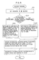
- the recording or writing process is performed through steps 101 to 103 in Fig. 1 as described later.
- the recrystallizing region will be explained below.
- the abscissa represents a laser irradiation time t p (pulse width), and the ordinate represents laser irradiation power P.
- the phase change state of the recording film consisting of an unchanging region, a recrystallizing region, an amorphousizing region, and a damaged region due to excessive heating is decided in accordance with t p and P.
- Each region basically depends on the heat temperature of the recording film.
- the boundary line has, on the longer irradiation time side, a more moderate gradient than the line with t x P - constant.
- the amorphousizing boundary line l2 with t p : short which is rightwardly descending can be made rightwardly ascending in the region with t p : long (Fig. 3A).
- the region partitioned by the melt line and the amorphousizing boundary line causes crystallization, it provides different operations. More specifically, the crystallization below the melt line only means that crystallization is facilitated in the solid state whereas the crystallization over the melt line means that the recording film is once melted at a temperature exceeding the melting point to be its liquid state and recrystallized in the cooling process.
- the region over the melt line is referred to as recrystallizing region.
- the recrystallization depends on the ratio of the passing time t c (time required to pass the crystallization temperature region in the cooling process from the melting point) to the crystallization time ⁇ (Tn), i.e., t c / ⁇ (Tn).
- t c / ⁇ (Tn) large (» 1)
- t c / ⁇ (Tn) small ( « 1)
- the film is difficult to be recrystallized since it is abruptly cooled from the liquid phase and is quenched to be amorphous.
- the first passing time factor t c ⁇ defined by the heat dissipating constant is large as the thermal capacity of the recording film is small and the thermal conduction of the neighboring material is high.
- the irradiation power is enhanced with the heat dissipating constant fixed, the temperature change per unit time is increased so that the time required to pass the crystallization temperature region is decreased. Then, the second passing time factor t c ⁇ becomes small. Moreover, if the irradiation time t c is increased, the effective thermal capacity appears to have been increased due to the thermal diffusion from the laser spot portion during irradiation. Then, the effective heat dissipating constant becomes large and the cooling speed becomes low so that the third passing time factor t c ⁇ becomes large.
- the recrystallization state depends on which of t c ⁇ , t c ⁇ , and t c ⁇ is dominant in the ratio of the passing time t c to the crystallization time ⁇ (Tn).
- the recording film at recording positions is melted while the irradiation laser power profile is controlled to cause a phase change between the amorphous state and the recrystallization state.
- the first passing time factor t c ⁇ which is a fixed component depending on the disk composition and make dominant the second and third passing time factors t c ⁇ and t c ⁇ .
- the heat dissipating constant can be decreased and so, the first passing time factor t c ⁇ can be decreased.
- (t c ⁇ + t c ⁇ ) can be controlled using the power profile. It is assumed that the average value of (t c ⁇ + t c ⁇ ) in a controllable range is t a , and a recording film having the crystallization time ⁇ (Tn) equal to t a . Then, the value of (t c ⁇ + t c ⁇ )/ ⁇ (Tn) can be varied centering 1 by changing the power profile of the irradiation laser.
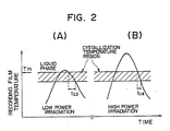
- Figs. 2A and 2B show the temperature profiles of the recording film when a metallic film with enhanced heat dissipating property is provided in thermal coupling with the recording film so as to decrease t c ⁇ .
- t c ⁇ When t c ⁇ is decreased, the thermal response speed during laser irradiation is enhanced so that the temperature profile can respond to the power profile of a laser spot itself in Gaussian distribution when the laser spot passes.
- the temperature profile is also similar to the Gaussian distribution. Specifically, temperature changes slowly around the peak of the temperature profile and changes rapidly around the middle thereof. When low power is irradiated, as seen from Fig.
- the temperature of the recording film passes the crystallization temperature region where temperature change is moderate, so that the passing time t c 3 during low power irradiation becomes long. Then, the recording film is cooled slowly from the liquid phase and recrystallized.
- the temperature of the recording film passes the crystallization temperature region where temperature change is abrupt, so that the passing time t c 4 is short during high power irradiation. Then, the recording film is cooled quickly from the liquid phase and is made amorphous.
- the boundary partitioning the recrystallizing region and the amorphousizing region is a rightwardly ascending line.
- the irradiation power profile to increase a change of t c ⁇ and also adjusting thermal diffusion to restrict t c ⁇ so as to make t c ⁇ more dominant, the gradient of the boundary line between the recrystallizing region and the amorphousizing region can be made moderate.
- the gradient of the boundary line can be made abrupt.
- a recording medium with a recrystallizing region and the adjusted gradient of the boundary between it and an amorphousizing region can be provided. Then, if the single beam overwrite is performed between the recrystallizing region and the amorphousizing region, all the operating points are located at the temperatures exceeding the melting point. Thus, the recording film of the recording position is melted and once expeniences the liquid phase. Therefore, the difference of crystallization rate among the previous state of the operating points, which is a cause of incomplete erasing in the overwrite, can be removed. Through the melting, the recording film of the recording position is subjected to perfect erasing, thereby providing a high erasing ratio or high erasing capability.
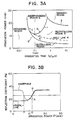
- the boundary line of an amorphousizing region is indicated by a reference numeral 1, that of a crystallizing region is indicated by a numeral 2, that of a damaged region is indicated by a numeral 3, and a melt line is indicated by a numeral 4.
- the solid line is a graph when the initial state is in a crystalline state, and the broken line is a graph when the initial state is in an amorphous state.
- the reflection coefficient starting from the crystalline state starts to increase at the irradiation power of 9 mW and is saturated at that of 14 mW.
- the reflection coefficient starting from the amorphous state starts to decrease at an irradiation power of 6 mW, becomes the reflection coefficient corresponding to a crystalline state at an irradiation power of 9 mW, starts to increase there again, and is saturated at an irradiation power of 14 mW or more, thus providing a reflection coefficient corresponding to the amorphous state again.
- the intermediate level between the reflection coefficients corresponding to the crystalline state and the amorphous state is a boundary of phase change
- 7 mW is crystallizing power
- 12 mW is amorphousizing power
- 9 mW is melting power P M .
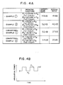
- Fig. 4A shows, in comparison between embodiments (examples) of the present invention and examples of the prior art, characteristics or CNR (ratio of carrier signal level to noise) and erasing ratio when single beam overwrite is performed between the frequency of 2 MHz and 3 MHz; the erasing ratio means what amount of 2 MHz signal is erased when 3 MHz signal is written on 2 MHz signal.
- CNR ratio of carrier signal level to noise
- Fig. 5 shows steps for implementing this operation. Accordingly, a high CNR of 49 dB can be realized and also a high erasing ratio of 41 dB, which is due to the fact that the operation point is set at a temperature or the melting point or more, can be realized.
- Example 2 will be explained.
- the single beam overwrite is performed between the recrystallizing region and the amorphousizing region which is not located above the recrystallizing region.
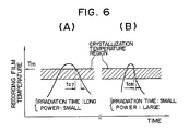
- Fig. 6A shows the same temperature profile with the same laser power and irradiation time as that of Example 1 shown in Fig. 2A.
- the irradiation time is decreased and the power is increased so that the maximum temperature of the recording film reaches the same temperature as in Fig. 6A.
- the temperature of the recording film abruptly decreases since due to the short irradiation time, laser irradiation stops before the laser spot passes the recording position.
- the temperature profile of Fig. 6A accords with the passing of the laser beam and exhibits a gradual temperature fall under the influence of the power distribution of the laser beam spot.
- the temperature profile of Fig. 6A accords with the passing of the laser beam and exhibits a gradual temperature fall under the influence of the power distribution of the laser beam spot.
- the passing time t c 1 is long whereas in the temperature profile of the high power and short irradiation time, the passing time t c 8 is short. Therefore, by controlling the passing time between t c 7 and t c 8, the recording film at the recording position can be subjected to the phase change between a crystalline state and an amorphous state.
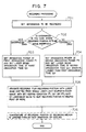
- Fig. 28 shows steps 701 to 705 for recording information by this recording technique (step 706 is optional).
- Example 2 the CNR of 52 dB and the erasing ratio of 40 dB can be realized. Since the operating points are set for both amorphousizing and crystallizing modes at the temperature of the melting point or more in Example 1, such a high erasing ratio can be obtained. Further, since the recording in the amorphousizing mode is carried out in a shorter irradiation time than Example 1 to increase the cooling speed thereby to facilitate the amorphousizing so as to increase change of the reflection coefficient, such a high CNR can be obtained.
- Example 1 the time of the laser beam spot passing the recording position is 0.2 ⁇ s whereas the recording laser irradiation time with the signal at 2 MHz is 0.25 ⁇ s (duty factor : 50%).
- Example 2 it will be understood that pulses having a pulse width of 0.05 ⁇ s which is shorter than the passing time 0.2 ⁇ s of the beam spot.
- the recording operation in the crystallizing mode is at the temperature lower than the melting point so that the previous history cannot be removed and so a high CNR of 52 dB can be obtained but the erasing ratio is as low as 27 dB.
- the conventional Example 2 is directed to the case where the recording in the amorphousizing mode is carried out with short irradiation time t p as in Example 2.
- more abrupt cooling facilitates the amorphousizing so that the CNR is enhanced to 54 dB whereas the erasing ratio is greatly lowered to 20 dB.
- the conventional examples in which there is a great difference in the crystallizing rate between the amorphous portion and the crystal portion in the previous history and the previous history cannot be removed, provides a high CNR but also a decreased erasing ratio.
- Examples 1 and 2 of the present invention provide substantially equal erasing ratios and have an advantage of providing high erasing ratio irrespectively of the irradiation time t p .
- the first erasing power P1 for amorphousizing must be increased to a value as high a 16 mW for the recording in the amorphousizing mode with a short irradiation time whereas the irradiation power P3 for crystallizing used is as low as 8 mW. Then, the ratio P1/P3 is large so that the width of the heating region with an equal laser power density is greatly shifted between the recording portion in the amorphousizing mode and the recording portion in the crystallizing mode and winds on a recording track. This winding also promotes incomplete erasure.
- a recrystallizing region is formed as an operating property to place operating points in the crystallizing mode therein.
- the recrystallizing region is set on the side of higher power than only a crystallizing region so that the ratio P1/P2 can be decreased and so, incomplete erasure can be restrained.
- Fig. 10 shows the arrangement of an optical disk in accordance with the above examples of the present invention.
- the optical disk is composed of an aluminium nitride film (AlN film) 12, a recording film 13, another AlN film 14, an gold (Au) film 15, a further AlN film 16, and an ultraviolet ray setting resin film 17 stacked successively on a substrate 11 in the following arrangement.
- AlN film 12 having a thickness of 70 nm is formed as an interference film on the substrate with a tracking guide, of glass, having a diameter of 130 mm through the sputtering technique.
- the recording film 13, made of a tertiary system of indium-antimony-tellurium (In-Sb-Te), having a thickness of 50 nm is formed thereon through the sputtering technique.
- Another AlN film 14 having a thickness of 70 nm is formed thereon through the sputtering. Further, the Au film 15 having a thickness of 100 nm is thereon formed as a reflection film through through the sputtering technique. Finally, the further AlN film 16 as a protection film having a thickness of 100 nm and the ultraviolet ray setting resin film 17 having a thickness of 10 ⁇ m are spin-coated thereon.
- a tantalum pentaoxide (Ta2O5) film 122 having a thickness of 70 nm is formed as an interference/thermal protection film on an injection-molded replica substrate 111 formed of polycarbonate and having tracking guide; a recording film 131, made of a tertiary system of antimony-selenium-bismuth (Sb-Se-Bi), having a thickness of 90 nm is formed thereon; and another Ta2O5 film 161 having a thickness as a protection film is formed thereon.
- Sb-Se-Bi tertiary system of antimony-selenium-bismuth
- Fig. 12A shows partition of the phase change regions in the above optical disk.
- the thermal protection film is made of Ta2O5 which has lower thermal conductivity than AlN
- the recording film is made of Sb-Se-Bi which requires a longer crystallizing time than In-Sb-Te. Therefore, a recrystallizing region is shifted on the side of longer laser irradiation time as compared with Fig. 3A, and the recrystallizing region above which an amorphousizing region is located can be formed in the range of an irradiation time of 0.3 ⁇ s - 2 ⁇ s.
- Fig. 12B shows a relation between laser irradiation power P and a reflection coefficient at an irradiation time of 1 ⁇ s (linear speed : 1 m/s).
- the solid line indicates the case where the initial state is crystalline and the broken line indicates the case where the initial state is amorphous.
- the reflection coefficient in the amorphous state and the crystalline state in this disk is reverse to the case of Fig. 3B, namely, the crystalline state has a larger reflection coefficient.
- This is decided by the reflective index, the absorptive coefficient and the thickness of the Sb-Se-Bi film and the wavelength ( 830 nm) of the used laser, and he present invention does not depend on the value of the reflection coefficient in the amorphous and crystalline states.
- the crystallizing power is 6 mW
- the melt power is 10 mW
- the amorphousizing power is 13 mW.
- the overwrite is repeated at frequencies of 0.5 MHz and 0.7 MHz.
- this example permits recording to be performed with the frequency and the pulse width (and so irradiation time t) being changed, thereby providing a high CNR and a high erasing ratio at a low linear speed.
- Fig. 13 shows the arrangement of an optical disk which is adapted to the use in which the linear speed varies in the range of 5 m/s to 12 m/s in the inner and outer peripheries in a 5.25 inch disk in a CAV (angular speed: constant) system for data storage.
- CAV angular speed: constant
- a silicon nitride (SiN) film 122 having a thickness of 70 nm is formed as an interference film on a glass substrate 112 having a tracking guide, a tertiary InSbTe system film 132 having a thickness of 60 nm is formed as a recording film thereon; another SiN film 142 having a thickness of 150 nm is formed thereon; a copper (Cu) film 152 having a thickness of 80 nm is formed as a reflection film thereon; and a further SiN film 16 having a thickness of 100 nm is formed thereon. These films are formed through the sputtering technique. Finally, an ultraviolet ray setting resin film 172 having a thickness of 100 ⁇ m is spin-coated thereon.
- the arrangement of the disk shown in Fig. 13 is basically the same as the disk (Fig. 10) used in Examples 1 and 2. However, the former is different from the latter in the following points.
- SiN which has substantially the same reflactive index as AlN but, lower thermal conductivity than AlN is used to advance the start of the recrystallization.
- the reflection film in place of gold, copper which has a reflection coefficient equal to and a higher thermal conductivity than gold is used in order to switftly cool the recording film heated by laser irradiation propagating to the reflection film 152 through the SiN film 142, thereby restraining the recrystallization due to the irradiation with high power and for long time.
- abrupt ascending of the boundary between the recrystallizing region and the amorphousizing region is restrained to extend the width of the recrystallizing region above which the amorphousizing region is located in the direction of irradiation time.
- Fig. 14A shows partition of phase change regions in the above disk.
- the amorphousizing region boundary line exhibits a rightwardly gradually ascending curve on the side of longer irradiation time than 0.08 ⁇ s.
- Reference numeral 4 denotes a melt line
- 5 denotes a recrystallizing region
- 6 denotes an amorphousizing region.
- the amorphousizing region is located above the recrystallizing region in a wide range of irradiation time of 0.08 ⁇ s - 1 ⁇ s.
- Fig. 14B shows a relation between irradiation power and a reflection coefficient with an irradiation time of 0.1 ⁇ s (corresponding to a laser spot diameter of 1 ⁇ m, a rotation number of 1800 rpm and a radius of 60 mm).
- Fig. 14C shows a relation between irradiation power and a reflection coefficient with a irradiation time of 0.2 ⁇ s.
- a and C are directed to the case measured at the operating point in the crystallizing mode and B and D are directed to the case measured at the operating point in the amorphousizing mode.
- the solid line indicates the case where the initial state is crystalline and the broken line indicates the case where the initial state is amorphous.
- the crystallizing power is 8 mW
- the melt power is 10 mW
- the amorphousizing power is 12 mW
- the crystallizing power is 5 mW
- the melt power is 8 mW
- the amorphousizing power is 14 mW.
- the overwrite is repeated at frequencies of 2.75 MHz and 3.75 MHz.
- a CNR of 48 dB and an erasing ratio of 40 dB are obtained in the inner periphery
- a CNR of 50 dB and an erasing ratio of 37 dB are obtained in the outer periphery.
- the phase state at the recording film of the recording position can be controlled.
- the flow chart of recording information in this case is illustrated by steps 1501 to 1508 in Fig. 15.
- the temperature profile of the recording film in this case is also shown in Figs. 16A and 16B.
- the maximum arrival temperature is higher than the case where the irradiation time is short since higher energy is provided with the same power. Since the maximum temperature is set higher in the cooling process, the profile passing the crystallization temperature can be set in a second moderate change region in the temperature profile.
- the temperature profile experiences a first moderate change in the neighborhood of the peak thereof, an abrupt change in the way and the above second moderate change in the low temperature region again. Further, the slope of the temperature profile is more moderate than the case of the short irradiation time due to the lengthened irradiation time.
- the profile passing the crystallization temperature region is a steep portion since the maximum arrival temperature is relatively low. Also, the profile slope itself is steep due to the shortened irradiation time.
- the passing time t c 5 through the crystallization temperature region in the case where the irradiation time is long can be lengthened, whereas the passing time t c 6 through the crystallization temperature region in the case where the irradiation time is short can be shortened.
- the phase state of the recording position can be controlled to be amorphous or crystalline, and the recording position, after once heated at a temperature higher than the melting point, can be overwritten. Then, the operating point of the crystallization corresponds to E point in Figs. 14A to 14C, and that of the amorphousizing corresponds to F point therein.
- the basic idea of the present invention as shown in the flow chart of Fig. 1, to once heat the recording film at a recording position to the temperature of the melting point or more, and thereafter change the time required for the temperature of the heated recording position to pass through the crystallization temperature region in accordance with whether information to be recorded is amorphous or crystalline.
- the previous history can be removed, by melting the recording film thus realizing the overwrite with a high erasing ratio.
- Fig. 17 shows a relation between the linear speed V and the erasing ratio.
- the present invention has an advantage of providing a high erasing ratio irrespectively of the linear speed.
- the irradiation power (more precisely irradiation power linear density) is larger in the inner periphery with a lower linear speed so that spread of heat in the direction of track width is larger in the inner periphery, which gives rise to problems of increase of crosstalk and erasure of neighboring tracks.
- Fig. 18 shows relations between the gradient M of the amorphousizing boundary line, the crosstalk due to expansion of the recording pits in the inner periphery and the erasing ratio in the neighboring tracks (represented by reduction of the carrier level therein) when the gradient of the amorphousizing boundary line is varied by varying the film thickness of the reflection film of Au or Cu in the disk of Fig. 10 or Fig. 13, or using an aluminum (Al) film having thermal conductivity than Au and Cu.
- P1 and P2 at the respective operating points are optimized so as to provide a high CNR and a high erasing ratio.
- the gradient M of the amorphousizing boundary line expressed by where P p1 : irradiation power on amorphousizing boundary line at the laser irradiation time T p1 P p2 : irradiation power on amorphousizing boundary line at the laser irradiation time T p2 t p1 : laser irradiation time in the outer periphery t p2 : laser irradiation time in the inner periphery.
- the crosstalk and the erasure of the neighboring track can be restrained so that the single beam overwrite can be performed for an optical disk in which the linear speed varies doubly.
- t p2 /t p1 ⁇ 2 it is preferable to set the radius ratio between the outermost track and the innermost track twice or more in view of the recording capacity. Then, t p2 /t p1 ⁇ 2, therefore, it is preferable to set t p2 /t p1 ⁇ 3 with a 1.5 times margin for operating shake.
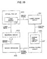
- Fig. 19 is a block diagram of the arrangement of one embodiment of an optical information recording device.
- 191 is a laser light source for irradiating a laser beam spot to a recording position in the recording film of a recording medium 192.
- Reference numeral 193 denotes an optical pick-up including the laser light source.
- Reference numeral 194 denotes a laser driving circuit for driving the laser light source 191 in the optical pick-up 193
- reference numeral 195 denotes a moving mechanism for relatively moving the recording medium 192 and the optical pick-up 193.
- Reference numeral 196 denotes a system control circuit for controlling the moving mechanism 195 and also controlling the laser driving circuit 194 on the basis of predetermined information.
- the system control circuit 196 incorporates a passing time control circuit 197 for controlling the laser driving circuit 194 so that the recording position in the recording medium 192 is heated at the melting point or more regardless of the information to be recorded and controlling the time required for the recording position to pass the crystallization temperature region of the recording medium 192 after the recording position has been heated at the melting point or more, in accordance with information to be recorded.
- the system control circuit 196 first sends a moving control signal to the moving mechanism 195 to shift the recording medium 192 relatively for the optical pick-up 193.
- the system control circuit 196 sends a laser driving control signal corresponding to the information to be recorded to the laser driving circuit 194 with reference to the passing time control circuit 197.
- the system control circuit 196 sends to the laser driving circuit 194 a control signal for heating the recording position to apply the laser beam to the melting point or more to shorten the passing time required to pass the crystallization temperature region.
- the laser driving circuit 194 sends a driving signal to the laser light source 191.
- the laser light source 191 irradiates the laser beam to the recording medium 192.
- the amorphousizing of the recording position can be implemented, for example, by irradiating the laser with high power and with a narrow pulse width so as to shorten the irradiation time, thereby to shorten the time required to pass the crystallization temperature region of the recording medium.
- the laser light source 191 is driven so as to heat the recording position to the melting point or more and also to irradiate it with the laser with low power and a wide pulse width increasing the irradiation time with reference to the passing time control circuit 197.
- the passing time required to pass the crystallization temperature region can be increased, thus crystallizing the recording film of the recording position.
- the recording film of the recording position is heated to the melting point or more to remove the previous history at the time of overwrite by melting the recording film of overwriting position, thereby providing an optical information recording apparatus with a high erasing ratio and few errors.
- the passing time control circuit 197 may be placed outside the system control circuit 196.
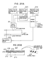
- Fig. 20A shows the arrangement of an optical information recording/reproducing apparatus in accordance with one embodiment of the present invention.
- This apparatus comprises an optical pick-up 221 irradiating a laser beam 231 to an optical disk 227 having a tracking guide, an optical pick-up position control circuit 222, a received light signal processing circuit 223, a semiconductor laser driving circuit 224, a disk rotating motor 225, a turn table 226, a recording condition discriminating circuit 228 for an optical disk recording film, a system control circuit 229, and a group of external input/output terminals.
- the optical disk 227 is formed of an AlN film 271, an In-Sb-Te system thin film 272, another AlN film 273, an Au film 274, a further AlN film 275, and an ultraviolet ray setting resin film 276 successively stacked on a glass substrate 270.
- the AlN film 271 having a thickness of 70 nm on the glass substrate 270, the In-Sb-Te system thin film 272 having a thickness of 50 nm is formed as a recording film thereon; another AlN film 273 having a thickness of 70 nm is formed thereon; the Au film 274 having a thickness of 100 nm is formed thereon: and the further AlN film 275 having a thickness of 100 nm is formed as a protection film thereon.
- These films are formed through the sputtering technique.
- the ultraviolet ray setting resin film 276 having a thickness of 10 ⁇ m is spin-coated as a protection film thereon.
- the optical disk 227 is placed on the turntable 226, which is rotated by the motor 225 so as to rotate the optical disk 227.
- the on-off control of rotation is performed through the system control circuit 229 from the external input/output terminals 230.
- the optical disk 227 is irradiated with the laser beam 231 from the optical pick-up 221.
- a reflection light of the laser beam 231 returns to the optical pick-up 221.
- the reflection light is sent to the received light signal processing circuit 223 to provide a signal indicating the height of the optical pick-up and a signal indicating a deviation or difference of the pick-up on a track thereof.
- the optical pick-up position control circuit 222 uses these signals to provide focusing and tracking of the optical pick-up for the optical disk.
- the on-off control of the focusing and tracking is performed through the system control circuit 229 from the external input/output terminals 230.
- optical pick-up 221 can be set every moment at optical irradiation power by the system control circuit 229 through the semiconductor driving circuit 224, which permits overwrite by a single beam.
- a control 232 track provided in the inner periphery or outer periphery of the optical disk 227 is the data record 233 of the melting point of the recording film in the optical disk 227, or the recording condition (irradiation power, passing time or irradiation time required for amorphousizing or crystallizing, etc.) required for heating the recording position to the melting point or more.
- This data record 233 is sent to the recording condition discrimination circuit 228 through the optical pick-up 221 and the received light processing circuit 223.
- the discrimination result is sent to the semiconductor laser driving circuit 224 through the system control circuit 229.
- the first irradiation power P1 and the second irradiation power P2 at the time of single beam overwrite can be set at the power for heating the recording film of the overwriting position to the melting point or more.
- reproduced information only passes the discrimination circuit 228 and is sent to the external input/output terminals 230 through the system control circuit 229.
- the recording condition discrimination circuit 228 may decode the data record 233 on the recording condition so as to permit the overwrite at the melting point or more; otherwise may obtain differences in the reflection coefficient during actual laser irradiation using a dummy track to provide the melt power P M for heating to the melting point from the difference.
- the recording condition data (8 bits) includes, for example, a 8-bit start code indicative of the start of the recording condition data, 32-bit data indicative of the melting point of the recording film, 32-bit data indicative of the passing data for amorphousizing after molten, 32-bit data indicative of the passing time for crystallization after molten, and 8-bit end code indicative of the end of the recording condition data.
- the recording condition data includes a 8-bit start code, 32-bit data irradiation power data and 32-bit irradiation time data for heating the recording film to the melting point or more for amorphousizing, 32-bit irradiation power data and irradiation time data indicative of the irradiation time for heating the recording film to the melting point or more for crystallization, and 8-bit end code.
- the history of the information previously recorded can be removed by once heating the recording film to the melting point to be molten in both amorphousizing overwrite mode and crystallizing overwrite mode, thus providing a high erasing ratio. Also by setting the crystallization time of the recording film at a longer time than the laser irradiation time, a high CNR can obtained using a single beam.
- a method and apparatus for recording optical information and a recording medium used therefor which permit the overwrite using a single beam with a high erasing ratio.
Abstract
Description
- The present invention relates to a method and apparatus for optically recording information and a recording medium therefor, and more particularly to those which permit overwrite using a single beam and can provide high overwrite erasing capability.
- As a technique of optically recording and reproducing information, it is known to use a phase-change film as a recording medium, and change laser irradiation power to cause the phase change thereof, thereby changing the optical property thereof so as to record and reproduce information. Among techniques of using the phase-change film, the technique of overwriting new data on old data while modulating the irradiation intensity of a single laser beam is disclosed in the technical search reports by the Japanese literature "DENSI JOHO TSUSIN GAKKAI, SINGAKU GIHO", Vol. 87, No. 310 CPM87-88, 88, 89, 90.
- The operation of the prior art single beam overwrite disclosed in the references is summarized as follows. A laser beam having the power profile as shown in Fig. 22 is irradiated onto the optical disk (recording medium) having a phase-change recording film, as shown in Fig. 21. The power profile of this laser beam is such that the pulsating power P₁ for recording information at a recording position to be amorphous is superposed on the D.C. power P₂ for recording information to be crystalline.
- Fig. 23 shows a relation between the pulse width and power of laser radiation for the recording film and the phase change thereof. As seen from the figure, with the predetermined pulse width, by varying the irradiation power, the recording film can be changed to be crystalline or amorphous. Hereinafter, making or becoming crystalline is referred to as "crystallizing" and making or becoming amorphous is referred to as "amorphousizing".
- The prior art technique discloses the basic operation of implementing the phase-change single beam overwrite but has the following problem. Any consideration is not given for the property of the recording film and the recording condition which are required to provide a high erasing ratio, i.e. for the realization of sufficiently high erasing ratio required in actually performing the phase-change single beam overwrite. Thus, the prior art provides a low erasing ratio and so, a large error rate due to incomplete erasure of old data. Accordingly, the prior art cannot satisfy the required reliability.
- The above problem will be explained in detail below. The recording process in the phase-change recording system is roughly represented by the crystallization state of the recording film. The crystallization state can be expressed by formula of JMA (Johnson, Mehl and Avrami) as disclosed in the reference of Japan Journal of Applied Physics, Vol. 26 (1987) Supplement 26-4.
- The crystallization time τ(T) at the temperature T(K) of the recording film can be expressed by
τ(T) = ν x exp(Ea/kT+Q/((Tm-T)x(Tm-T)xT) (1)where ν: crystal nucleus frequency factor Ea: activation energy k: Boltzman constant Tm: melting point of the recording film Q: reaction constant number. - Fig. 24 shows a relation between the temperature T and the crystallization time τ(T) in Equation (1). In this figure, the temperature (abscissa) is represented by 1000/T. In a low temperature region on the right side of the figure, according to the increase of temperature, the crystallization time τ(T) is shortened. However, on the contrary, in a temperature region in the neighborhood of the melting point Tm, according to the increase of temperature, the crystallization time τ(T) is lengthened since the dissociation probability of atoms is increased as the temperature approaches the melting point Tm of the recording film.
- Namely, Equation (1) represents that the temperature where the crystallization time τ(T) is shortest and so the recording film is easily crystallized is located at the temperature slightly lower than the melting point Tm. This temperature where the crystallization time τ(T) is shortest is referred to as a nose temperature Tn since it looks like a nose tip.
- At the nose temperature Tn,
δ(τ(T))/δT=0
Tn is the root of the following Equation (2) when the differentiation of Equation (1) is set at zero.

The root is given, as shown in Fig. 25, by a T coordinate at the intersecting point of the third order curve having a coefficient of -1 passing a coordinate (Y, T) = (0, Tm)
Y = (Tm-T) and a line having a gradient of 3 x Q x k/Ea passing a coordinate (Y, T) = (0, Tm/3)
Y = 3 x Q x k/Ea x (T - Tm/3). - As the reaction constant number Q becomes large, the gradient of the line becomes large, so that the intersecting point is shifted towards T : small. On the other hand, as the activation energy Ea becomes large, the gradient of the line becomes small, the intersecting point is shifted T : large.
- Fig. 26 shows a relation between Q x k/Ea and the nose temperature Tn obtained using formula of Cardann.
- The crystallization rate X when the temperature is held at the temperature T for a time t is represented by
δX = 1-exp {-(δt/τ(T))n} (3)
where n: reaction constant. In the phase-change recording film, n=2∿3. - The crystallization of a recording film when it is heated from a room temperature to high temperatures through laser irradiation thereto accords with the integration of the crystallization rates at the respective temperatures in Equation (3) in accordance with the temperature profile.
- In a phase-change optical disk, laser heating is completed in a short time within 1 microsecond and the maximum heating temperature exceeds the melting point, so that the crystallization through the temperature profile occurs in the neighborhood of the nose temperature Tn where the crystallization time τ(Tn) is shortest. In the temperature range where the crystallization time is longer by one order of magnitude or more than the crystallization time τ(Tn) at the nose temperature Tn, the approximation δt/τ(T) « 1 can be taken and so the crystallization rate δX is substantially zero. Therefore, this temperature region does not contribute to the crystallization. The temperature region participating in the crystallization where the crystallization time τ(T) < (10 x τ(Tn)) is referred to as a crystallization temperature region or zone.
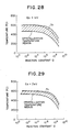
- Figs. 27 to 29 show changes of the nose temperature Tn and the crystallization temperature region relative to changes of the activation energies Ea (0.5 eV, 1 eV, and 2 eV) and the activation constant Q at Tm=600 C, respectively. As seen from the figures, with the increase of Q, Tn is lowered while with the increase of Ea, the width of the crystallization temperature region is narrowed.
- Fig. 22 shows the power profile of the irradiated laser during the single beam overwrite. This profile consists of two levels of power P₂ continuously light-emitting for crystallizing and power P₁ for amorphousizing superposed with recording pulses thereon.
- Fig. 30A and 30B schematically show the temperature of the recording film when the crystallizing power P₂ and amorphousizing power P₁ are irradiated in accordance with the laser power profile shown in Fig. 22, and the crystallization rate represented by the previously mentioned formula of JMA. The rotation number of the disk is set at 1800 rpm, the linear speed is set at 10 m/s, and the laser spot diameter is set at 1 µm.
- Now, consideration will be taken about the passing time required for the recording film to pass the crystallization temperature region in the neighborhood of the nose temperature Tn. In the crystallizing mode where the laser emits light continuously, the
time t c1 passing the crystallization temperature region, which is the time when the laser spot passes at the linear speed of 10 m/s, is about 0.1 µs. - On the other hand, in the amorphousizing mode where pulsating power is superposed on the irradiation power P₂ of the laser beam, the resulting temperature profile is the temperature profile in the crystallizing mode superposed with the temperature profile corresponding to the pulse component. Since the recording film is once melted at the temperature of the melting point or more, the time required to pass the crystallization temperature region has only to be considered on the cooling process after the melting. Thus, the
time t c2 passing the crystallization temperature region is about 0.05 µs, which is about 1/2 ort c1. - However, unlike the double beam overwrite, the single beam overwrite can not change the laser spot diameter for the amorphousizing mode in which the recording position is made amorphous and the crystallizing mode in which the recording position is made crystalline, the passing time in the crystallization temperature region varies only about double between the amorphousizing and crystallizing modes, namely can not greatly vary.
- Consideration will be taken here about the crystallization rate in the amorphousing and crystallizing modes. Although the crystallization is strictly represented by the integration of the crystallization rates in accordance with the temperature profile, it can be roughly decided by the tc/τ(Tn) (tc: passing time required for the temperature of the recording film to pass the crystallization temperature region in the neighborhood of the nose temperature Tn: crystallization time τ(Tn) at the nose temperature). With the passing time tc » τ(Tn), the crystallization rate is 100% (complete crystalline phase). And, with the passing time tc « τ(Tn), the crystallization rate is 0% (complete amorphous phase). The crystallization time τ(Tn) is previously defined with the recording film, and the passing time tc varies only about double as mentioned above. Therefore, the crystallization in the crystallizing and amorphousizing modes in accordance with the power profile of the single beam overwrite as shown in Fig. 22 can not provide the crystallization rate of 100% in the crystallizing mode and that of 0% (amorphous) in the amorphousizing mode, as shown in Figs. 30A and 30B.
- If the recording film having short crystallization time τ(T) is selected in order to provide the crystallization rate of 100%, the passing time tc in the crystallizing mode i.e. t » τ(Tn) is satisfied. However, since the passing time varies slightly only double in the amorphousizing and crystallizing modes, the passing time tc » τ(Tn) results also in the amorphousizing mode. Thus, although the amorphous phase is intended to be provided in the recording mode, the crystallization rate at the recording position becomes almost equal to that in crystallizing mode and thus, there is no difference of the crystallization rate between the crystallizing and amorphousizing modes. Since recording/reproduction uses that difference of the crystallization rate leads to that of a reflection coefficient, the absence of difference in the crystallization rate substantially makes it impossible to record and reproduce signals.
- In order to carry out the recording so as to provide a necessary reproduction signal level, it is necessary to set the crystallization time τ(Tn) of the recording film at a moderately large value ta which is an intermediate value between the passing
time t c1 in the crystallizing mode and the passingtime t c2 in the amorphousizing mode (τ(Tn) = ta). Therefore, it is impossible to attain the crystallization rate of 100% in the crystallizing mode. In Figs. 30A and 30B τ(Tn) at the nose temperature Tn is set at 40 nanoseconds, which results in
the crystallization rate in the crystallizing mode: 80%
the crystallization rate in the amorphousizing mode: 40% - The conventional single beam overwrite is involved in the above restrictions. Now, explanation will be given for the crystallization rate in amorphousizing mode and that in the crystallizing mode in the overwrite under the above restrictions.
- In the amorphousizing mode, the recording film at the recording position is once melted to enter the liquid phase and is recrystallized in the abrupt cooling process from the liquid phase to the solid phase so that its crystallization rate remains constant and is 40%. On the other hand, in the crystallizing mode, the film is not melted and one round process of the crystallizing mode can not provide complete crystalline state with the crystallization rate of 100% so that the influence of the old crystallization rate of the recording position before new crystallization is left as a previous history. If the previous phase at the recording position is crystalline as previous history, the crystallization rate has already reached 80% and the remaining 20% part of amorphous portion which is not still crystallized is facilitated to be crystallized. The crystallization rate of the amorphous portion (uncrystallized portion) is 80% when the new crystallizing is carried out by once irradiating laser. Thus, the new crystallization rate after having experienced the crystallizing mode becomes 96% (the initial crystallization rate of 80% plus the crystallization facilitating rate of 16% for the uncrystallized portion). If the previous history has experienced the amorphousizing mode just before, the initial crystallization rate is 40%, and the new crystallization rate after having experienced the crystallizing mode this time becomes 88% (the initial crystallization rate of 40% plus the crystallization facilitating rate of 48%).
- In this way, in crystallizing mode, even though the recording film is in a crystalline phase, the film has portions with different crystallization rates of 96% and 88% which are provided depending upon the previous history. This difference leads to incomplete erasing, which gives rise to a problem of providing an insufficient erasing ratio of the old data history in the overwrite.
- This problem is particularly remarkable in an optical disk in a CAV (Constant Angular Velocity) system with constant rotating speed in which the linear speed is different in inner and outer peripheries. The laser irradiation time for crystallizing the recording position is limited within the time t of a laser spot passesing through the recording position. The time t is defined by t = (laser spot diameter)/(linear speed), and the laser spot diameter is set constant. In the CAV disk, the linear speed in the outer periphery is relatively large so that the laser irradiation time for crystallizing the recording position is shortened. Thus, the crystallization in the crystallizing mode can not be sufficiently facilitated so that erasing ratio is disadvantageously lowered particularly in the outer periphery. Further, in the prior art, the irradiation power P₁ in the amorphousizing mode and the irradiation power P₂ in the crystallizing mode are set at 20 mW and 10 mW, respectively (P₁/P₂ = 2) so that the width of the heating region at recording positions is varied in a track width direction for the amorphousizing mode and crystallizing mode. This also leads to incomplete erasure.
- An object of the present invention is to provide a method and apparatus for optically recording information and a recording medium therefor which permit overwrite using a single beam with a high erasing ratio.
- In order to attain the above object, the operation point of irradiated laser power is set for both amorphousizing mode and crystallizing mode at power which permits a recording film to be heated at a temperature or its melting point or more and also the heat dissipating property of the recording film and its neighboring material is adjusted so that the cooling time after melted (the passing time required to pass the crystallization temperature region of the recording film in a cooling process) is varied by the irradiated power. Further, the crystallization time of the recording film is also set within a range of controlling the cooling time by the above laser power so that a phase change optical information recording medium has, as its phase change property during laser irradiation, an amorphousizing region and a recrystallizing region. Information is recorded through the phase change between the amorphousizing region and the recrystallizing region. The recording or writing process is performed through
steps 101 to 103 in Fig. 1 as described later. - The recrystallizing region will be explained below. In Fig. 23, the abscissa represents a laser irradiation time tp (pulse width), and the ordinate represents laser irradiation power P. Then, the phase change state of the recording film consisting of an unchanging region, a recrystallizing region, an amorphousizing region, and a damaged region due to excessive heating is decided in accordance with tp and P. Each region basically depends on the heat temperature of the recording film. Arranged from the low power side are the unchanging region, the crystallizing region over a crystallization boundary line ℓ₁ (corresponding to the temperature Tn), the amorphousizing region over an amorphousizing boundary line ℓ₂ (corresponding to the melting point Tm in the region with the pulse width tp of 10 ns or less), and the damaging region over a damage boundary line ℓ₃. Since the reached temperature is substantially proportional to the irradiation energy (t x P), each boundary line is a line with t x P = constant, having a rightwardly descending tendency. With the increase of the irradiation time thermal diffusion occurs in the increased irradiation time so that in order to equally hold the reached temperature, the larger the power, the longer is required the irradiation time. Thus, the boundary line has, on the longer irradiation time side, a more moderate gradient than the line with t x P - constant.
- Here, as mentioned above, by adjusting the crystallization time and the cooling time of the recording film, the amorphousizing boundary line ℓ₂ with tp: short which is rightwardly descending can be made rightwardly ascending in the region with tp: long (Fig. 3A).
- Now, taken is the line ℓ₄ obtained by extrapolating the amorphousizing boundary line ℓ₂ in the region with tp: short to the region with tp: long so that it is parallel to the crystallizing boundary line ℓ₁. This extrapolating boundary line ℓ₂ (representing that the recording film has reached its melting point) with tp: short is substantially equal to the extrapolation in parallel to the crystallizing boundary line ℓ₁ so that it provides the constant reached temperature and so can be regarded as a boundary where the temperature of recording film reaches its melting point (hereinafter referred to as a melt line).
- Incidentally, although the region partitioned by the melt line and the amorphousizing boundary line causes crystallization, it provides different operations. More specifically, the crystallization below the melt line only means that crystallization is facilitated in the solid state whereas the crystallization over the melt line means that the recording film is once melted at a temperature exceeding the melting point to be its liquid state and recrystallized in the cooling process. The region over the melt line is referred to as recrystallizing region.
- The operation of the present invention will be roughly explained below. The recrystallization depends on the ratio of the passing time tc (time required to pass the crystallization temperature region in the cooling process from the melting point) to the crystallization time τ(Tn), i.e., tc/τ(Tn). With tc/τ(Tn) : large (» 1), the film is easy to be recrystallized since it is gradually cooled from the liquid phase whereas with tc/τ(Tn) : small ( « 1), the film is difficult to be recrystallized since it is abruptly cooled from the liquid phase and is quenched to be amorphous.
- The passing time tc can be represented by a sum of a first passing time factor tcα which is defined by the heat dissipating time constant depending on the medium composition, a second passing time factor tcβ which is defined by the laser irradiation power, and a third passing time factor tcγ which is defined by the change of cooling property where the thermal diffusion changes in accordance with the irradiation time, i.e., tc = tcα + tcβ + tcγ. The first passing time factor tcα defined by the heat dissipating constant is large as the thermal capacity of the recording film is small and the thermal conduction of the neighboring material is high. Further, if the irradiation power is enhanced with the heat dissipating constant fixed, the temperature change per unit time is increased so that the time required to pass the crystallization temperature region is decreased. Then, the second passing time factor tcβ becomes small. Moreover, if the irradiation time tc is increased, the effective thermal capacity appears to have been increased due to the thermal diffusion from the laser spot portion during irradiation. Then, the effective heat dissipating constant becomes large and the cooling speed becomes low so that the third passing time factor tcγ becomes large.
- The recrystallization state depends on which of tcα, tcβ, and tcγ is dominant in the ratio of the passing time tc to the crystallization time τ(Tn).
- In the single beam overwrite for providing a high erasing ratio, it is required that the recording film at recording positions is melted while the irradiation laser power profile is controlled to cause a phase change between the amorphous state and the recrystallization state.
- To this end, it is necessary to make small the first passing time factor tcα which is a fixed component depending on the disk composition and make dominant the second and third passing time factors tcβ and tcγ. As mentioned above, if the heat dissipating property is enhanced in the disk composition, the heat dissipating constant can be decreased and so, the first passing time factor tcα can be decreased.
- In the disk composition with enhanced heat dissipating property.
tc/τ(Tn) = (tcβ + tcγ)/τ(Tn) - As mentioned previously, if the power is increased, tcβ is decreased and if the irradiation time is increased, tcγ is increased. Thus, (tcβ + tcγ) can be controlled using the power profile. It is assumed that the average value of (tcβ + tcγ) in a controllable range is ta, and a recording film having the crystallization time τ(Tn) equal to ta. Then, the value of (tcβ + tcγ)/τ(Tn) can be varied centering 1 by changing the power profile of the irradiation laser.
- With (tcβ + tcγ)/ (Tn) » 1, the recording film will be recrystallized since it is gradually cooled after melted. With (tcβ + tcγ)/τ(Tn) « 1, the recording film will be made amorphous since it is abruptly cooled after melted.
- Figs. 2A and 2B show the temperature profiles of the recording film when a metallic film with enhanced heat dissipating property is provided in thermal coupling with the recording film so as to decrease tcα. When tcα is decreased, the thermal response speed during laser irradiation is enhanced so that the temperature profile can respond to the power profile of a laser spot itself in Gaussian distribution when the laser spot passes. Thus, the temperature profile is also similar to the Gaussian distribution. Specifically, temperature changes slowly around the peak of the temperature profile and changes rapidly around the middle thereof. When low power is irradiated, as seen from Fig. 2A, the temperature of the recording film passes the crystallization temperature region where temperature change is moderate, so that the passing
time t c3 during low power irradiation becomes long. Then, the recording film is cooled slowly from the liquid phase and recrystallized. On the other hand, when high power is irradiated, as seen from Fig. 2B, the temperature of the recording film passes the crystallization temperature region where temperature change is abrupt, so that the passingtime t c4 is short during high power irradiation. Then, the recording film is cooled quickly from the liquid phase and is made amorphous. - The condition of (tcβ + tcγ)/τ(Tn) = 1 is a criterion of the boundary between the crystallized state and the amorphous state. This boundary will be considered in relation to irradiation power and time below. If the power is increased, tcβ is decreased, and if the irradiation time is lengthened, tcγ is increased. Thus, the power satisfying the condition (tcβ + tcγ) = τ(Tn) when the irradiation time is long is higher than that when the irradiation time is short. Therefore, with the abscissa of an irradiation time and the ordinate of power, the boundary partitioning the recrystallizing region and the amorphousizing region is a rightwardly ascending line. Further, by adjusting the irradiation power profile to increase a change of tcβ and also adjusting thermal diffusion to restrict tcγ so as to make tcβ more dominant, the gradient of the boundary line between the recrystallizing region and the amorphousizing region can be made moderate. On the contrary, by restricting a change of tcβ so as to make tcγ more dominant, the gradient of the boundary line can be made abrupt.
- In this way, a recording medium with a recrystallizing region and the adjusted gradient of the boundary between it and an amorphousizing region can be provided. Then, if the single beam overwrite is performed between the recrystallizing region and the amorphousizing region, all the operating points are located at the temperatures exceeding the melting point. Thus, the recording film of the recording position is melted and once expeniences the liquid phase. Therefore, the difference of crystallization rate among the previous state of the operating points, which is a cause of incomplete erasing in the overwrite, can be removed. Through the melting, the recording film of the recording position is subjected to perfect erasing, thereby providing a high erasing ratio or high erasing capability.
- An example of the property having a recrystallizing region in a phase change optical information recording medium is disclosed in the previously identified reference, "SINGAKU GIHO" Vol. 87 No. 310 CPM87-80. However, there is not disclosed therein the use of the recrystallizing region and a technique of adjusting the recording medium to use the recrystallizing region thereby remarkably improving the erasing ratio. There is only disclosed a three-beam overwrite technique which is a previous stage of the use of the recrystallizing region.
- Further, it should be noted that the above reference makes division of the phase change in a static system and does not consider that the crystallization which is based on delicate thermal balance should be considered together with thermal propagation in the recording medium before and after laser irradiation in a moving system.
-
- Fig. 1 is a flow diagram of the basic steps of the present invention;
- Figs. 2A and 2B show the relation between the temperature profiles of the recording position and high and low irradiation power, respectively;
- Figs. 3A and 3B are characteristic graphs for explaining one embodiment of the present invention;
- Figs. 4A and 4B are a table showing the comparison result of a carrier-to-noise ratio (CNR) and an erasing ratio between the present invention and the prior art, and a graph showing the profile of irradiation power, respectively;
- Fig. 5 is a flow diagram of the recording process in accordance with one embodiment of the present invention;
- Figs. 6A and 6B are temperature profiles for explaining the recording method in accordance with the other embodiment of the present invention;
- Fig. 7 is a flow diagram of the recording process in accordance with the other embodiment of the present invention;
- Figs. 8 and 9 are a characteristic graph of irradiation power P₂ vs erasing ratio, and of a ratio of irradiation power P₁ to P₂ vs the erasing ratio respectively;
- Figs. 10, 11, and 13 are a sectional view of the structure of the recording medium in accordance with the embodiments of the present invention, respectively;
- Figs. 12A and 12B are a characteristic graph of a phase change and of laser irradiation power vs reflection coefficient in an optical disk in accordance with the embodiments of the present invention, respectively;
- Figs. 14A is a characteristic graph of a phase change, and Figs. 14B and 14C are characteristic graphs of laser irradiation power vs a reflection coefficient in an optical disk in accordance with an embodiment (example 4) of the present invention;
- Fig. 15 is a flow diagram showing the recording process in accordance with a further embodiment of the present invention;
- Figs. 16A and 16B are temperature profiles in accordance with another embodiment of the present invention;
- Figs. 17 and 18 are a characteristic graph of a linear speed vs erasing ratio and of crosstalk vs a carrier level, respectively;
- Fig. 19 is a block diagram of an optical information apparatus in accordance with one embodiment of the present invention;
- Figs. 20A and 20B are a block diagram of an optical information recording/reproducing apparatus in accordance with one embodiment of the present invention and an optical disk having controlled record used therefore, respectively;
- Figs. 21 to 23 are views for explaining the prior art, in which Fig. 21 is a sectional view of a prior art structure and also shows a relation between an optical disk and laser beam irradiation, Fig. 22 is a graph of the profile of irradiation power, and Fig. 23 is a characteristic graph of the phase change of a recording film;
- Fig. 24 is a characteristic graph of crystallization time vs temperature;
- Figs. 25 to 29 are characteristic groups for explaining a crystallization temperature region, respectively; and
- Figs. 30A and 30B are groups showing the crystallization process of a phase change recording film in the crystallizing mode and the amorphousizing mode in relation to the crystallization rate thereof, respectively.
- Referring to the drawings, explanation will be given for several embodiments. It should be now noted that the present invention can be applied to an optical disk in thin film structure disclosed in U.S. Application being filed on the basis of Japanese Patent Application No. 63-154743 filed June 24, 1988 assigned to the present assignee.
- Fig. 3A is a characteristic diagram of phase change regions in relation to laser irradiation power and irradiation time for an optical disk in accordance with one embodiment of the present invention. Measurements are made while changing a disk rotation number, radius, and laser irradiation power P using an optical pick-up having a laser spot diameter of φ = 1 µm. The irradiation time tp is set as follows
tp = φ x 60/2πRN where φ: laser spot diameter R: radius N: rotation number (rpm) - The boundary line of an amorphousizing region is indicated by a
reference numeral 1, that of a crystallizing region is indicated by anumeral 2, that of a damaged region is indicated by anumeral 3, and a melt line is indicated by anumeral 4. - The amorphousizing
region boundary line 1 is lowest at the laser irradiation time tp = tpo = 0.1 µs and rightwardly ascending at tp > 0.1 µs. Themelt line 4 is a line obtained by extrapolating the amorphousizingregion boundary line 1 at tp = 0.05 µs into the irradiation time zone of tp > 0.1 µs in parallel to the crystallizingregion boundary line 2. A region located between themelt line 4 and the amorphousizingregion boundary line 1. - Fig. 3B is a graph of the relation between the irradiation power P and the reflection coefficient when the irradiation power P is varied so as to pass the
recrystallizing region 5 with tp = 0.2 µs (N = 1800 rpm, R = 30 mm in Fig. 3A). The solid line is a graph when the initial state is in a crystalline state, and the broken line is a graph when the initial state is in an amorphous state. The reflection coefficient starting from the crystalline state starts to increase at the irradiation power of 9 mW and is saturated at that of 14 mW. The reflection coefficient starting from the amorphous state starts to decrease at an irradiation power of 6 mW, becomes the reflection coefficient corresponding to a crystalline state at an irradiation power of 9 mW, starts to increase there again, and is saturated at an irradiation power of 14 mW or more, thus providing a reflection coefficient corresponding to the amorphous state again. Now assuming that the intermediate level between the reflection coefficients corresponding to the crystalline state and the amorphous state is a boundary of phase change, 7 mW is crystallizing power, 12 mW is amorphousizing power, and 9 mW is melting power PM. - Fig. 4A shows, in comparison between embodiments (examples) of the present invention and examples of the prior art, characteristics or CNR (ratio of carrier signal level to noise) and erasing ratio when single beam overwrite is performed between the frequency of 2 MHz and 3 MHz; the erasing ratio means what amount of 2 MHz signal is erased when 3 MHz signal is written on 2 MHz signal.
- Example 1 is the case where the single beam overwrite is performed between an amorphousizing operation point B in the amorphousizing region and a recrystallizing operation point C in the recrystallizing region in Figs. 3A and 3B, the first irradiation power P₁ = 12.5 mW (high power) and the second irradiation power P₂ = 9.5 mW (low power) both of which are higher than the melt power PM = 9 mW which is capable of heating the recording position to the melting point or more and the irradiation time tp = 0.2 µs for the irradiation with both powers P₁ and P₂ in the irradiation power profile.
- The operation of selecting the phase (state) of a recording position between the amorphous state and the crystal state, as explained in connection with Figs. 2A and 2B, is implemented by changing the irradiation power so that the passing time tc required to pass the crystallization temperature region is short during high power irradiation (tc4) and long during low power irradiation (tc3) Fig. 5 shows steps for implementing this operation. Accordingly, a high CNR of 49 dB can be realized and also a high erasing ratio of 41 dB, which is due to the fact that the operation point is set at a temperature or the melting point or more, can be realized.
- Example 2 will be explained. In this example, the second irradiation power P₂ for crystallizing is the same as in Example 1 (P₂ = 9.5 mW (A point)). On the other hand, the first irradiation power P₁ for amorphousizing is set at P₁ = 16 mW. And recording is carried out at the C point using pulses with a reduced duty factor so as to provide the first irradiation time for
amorphousizing t p1 = 50 ns which is shorter than the second irradiation time for crystallizingt p2 = 0.2 µs. The single beam overwrite is performed between the recrystallizing region and the amorphousizing region which is not located above the recrystallizing region. - The operation in this example will be explained with reference to the temperature profile of a recording film as shown in Figs. 6A and 6B.
- Fig. 6A shows the same temperature profile with the same laser power and irradiation time as that of Example 1 shown in Fig. 2A. In the temperature profile shown in Fig. 6B, the irradiation time is decreased and the power is increased so that the maximum temperature of the recording film reaches the same temperature as in Fig. 6A. In this case, the temperature of the recording film abruptly decreases since due to the short irradiation time, laser irradiation stops before the laser spot passes the recording position. On the other hand, the temperature profile of Fig. 6A accords with the passing of the laser beam and exhibits a gradual temperature fall under the influence of the power distribution of the laser beam spot. Thus, in the temperature profile of Fig. 6A with the low power and long irradiation time, the passing
time t c1 is long whereas in the temperature profile of the high power and short irradiation time, the passingtime t c8 is short. Therefore, by controlling the passing time betweent c7 andt c8, the recording film at the recording position can be subjected to the phase change between a crystalline state and an amorphous state. Fig. 28 showssteps 701 to 705 for recording information by this recording technique (step 706 is optional). - Accordingly, in Example 2, the CNR of 52 dB and the erasing ratio of 40 dB can be realized. Since the operating points are set for both amorphousizing and crystallizing modes at the temperature of the melting point or more in Example 1, such a high erasing ratio can be obtained. Further, since the recording in the amorphousizing mode is carried out in a shorter irradiation time than Example 1 to increase the cooling speed thereby to facilitate the amorphousizing so as to increase change of the reflection coefficient, such a high CNR can be obtained.
- In Example 1, the time of the laser beam spot passing the recording position is 0.2 µs whereas the recording laser irradiation time with the signal at 2 MHz is 0.25 µs (duty factor : 50%). This means that pulsative waveforms as well as long pit signals can be recorded on the contrary, in Example 2, it will be understood that pulses having a pulse width of 0.05 µs which is shorter than the passing time 0.2 µs of the beam spot. Thus, by adjusting part of the amorphousizing region boundary line located above the recrystallizing region so that it is gradually ascending line, the range of the length of recordable pits can be extended.
- The setting of the crystallizing power (second irradiation power) P₂ is not restricted to P₂ = 9.5 mW. Fig. 8 is a graph of P₂ vs the erasing ratio. As seen from the figure, at the power exceeding P₂ = 9 mW, which provides a recrystallizing region, the erasing ratio exceeding 30 dB can be attained. Therefore, P₂ may be set so as to permit the operation in the recrystallizing region exceeding the power PM on the melt line.
- The conventional Example 1 is directed to the case where the single beam overwrite is performed to provide a phase change between the crystallizing region (but not the recrystallizing region) and the amorphousizing region setting the irradiation power in the crystallizing mode at a third power P₃ = 8 mW which can not heat the recording position to the melting point or more and the first irradiation power in the amorphousizing mode P₁ = 14 mW. In this case, the recording operation in the crystallizing mode is at the temperature lower than the melting point so that the previous history cannot be removed and so a high CNR of 52 dB can be obtained but the erasing ratio is as low as 27 dB.
- The conventional Example 2 is directed to the case where the recording in the amorphousizing mode is carried out with short irradiation time tp as in Example 2. In this example, more abrupt cooling facilitates the amorphousizing so that the CNR is enhanced to 54 dB whereas the erasing ratio is greatly lowered to 20 dB. The conventional examples, in which there is a great difference in the crystallizing rate between the amorphous portion and the crystal portion in the previous history and the previous history cannot be removed, provides a high CNR but also a decreased erasing ratio.
- Examples 1 and 2 of the present invention provide substantially equal erasing ratios and have an advantage of providing high erasing ratio irrespectively of the irradiation time tp.
- Further, in the conventional Example 2, the first erasing power P₁ for amorphousizing must be increased to a value as high a 16 mW for the recording in the amorphousizing mode with a short irradiation time whereas the irradiation power P₃ for crystallizing used is as low as 8 mW. Then, the ratio P₁/P₃ is large so that the width of the heating region with an equal laser power density is greatly shifted between the recording portion in the amorphousizing mode and the recording portion in the crystallizing mode and winds on a recording track. This winding also promotes incomplete erasure.
- On the other hand, in the Examples of the present invention, a recrystallizing region is formed as an operating property to place operating points in the crystallizing mode therein. The recrystallizing region is set on the side of higher power than only a crystallizing region so that the ratio P₁/P₂ can be decreased and so, incomplete erasure can be restrained.
- Fig. 9 shows a relation between the ratio P₁/P₂ and the erasing ratio with P₂ = 9 - 10 mW. Particularly, with P₁/P₂ (1.5, the erasing ratio of 30 dB or more can be obtained.
- Fig. 10 shows the arrangement of an optical disk in accordance with the above examples of the present invention.
- The optical disk is composed of an aluminium nitride film (AℓN film) 12, a recording film 13, another AℓN film 14, an gold (Au)
film 15, afurther AℓN film 16, and an ultraviolet ray settingresin film 17 stacked successively on a substrate 11 in the following arrangement. First, theAℓN film 12 having a thickness of 70 nm is formed as an interference film on the substrate with a tracking guide, of glass, having a diameter of 130 mm through the sputtering technique. The recording film 13, made of a tertiary system of indium-antimony-tellurium (In-Sb-Te), having a thickness of 50 nm is formed thereon through the sputtering technique. Another AℓN film 14 having a thickness of 70 nm is formed thereon through the sputtering. Further, theAu film 15 having a thickness of 100 nm is thereon formed as a reflection film through through the sputtering technique. Finally, thefurther AℓN film 16 as a protection film having a thickness of 100 nm and the ultraviolet ray settingresin film 17 having a thickness of 10 µm are spin-coated thereon. - Although the above example relates to the case where at the rotation number of the disk N = 1800 rpm, and the distance between the rotation center and the recording position (i.e. rotation radius) R = 30 mm i.e., the linear speed at the recording position V ≒ 6 m/s, this linear speed may be varied in the present invention.
- Fig. 11 shows the arrangement of an optical disk when the recrystallized region is set on the side of longer laser irradiation time so that the linear speed V of CD (compact disk), etc. corresponds to a system having a linear speed of V = 1 m/s. More specifically, a tantalum pentaoxide (Ta₂O₅)
film 12₂ having a thickness of 70 nm is formed as an interference/thermal protection film on an injection-molded replica substrate 11₁ formed of polycarbonate and having tracking guide; arecording film 13₁, made of a tertiary system of antimony-selenium-bismuth (Sb-Se-Bi), having a thickness of 90 nm is formed thereon; and another Ta₂O₅ film 16₁ having a thickness as a protection film is formed thereon. These films are formed through the sputtering technique. Further, an ultraviolet ray settingresin film 17 having a thickness of 10 µm is spin-coated. - Fig. 12A shows partition of the phase change regions in the above optical disk. In the above optical disk, the thermal protection film is made of Ta₂O₅ which has lower thermal conductivity than AℓN, and the recording film is made of Sb-Se-Bi which requires a longer crystallizing time than In-Sb-Te. Therefore, a recrystallizing region is shifted on the side of longer laser irradiation time as compared with Fig. 3A, and the recrystallizing region above which an amorphousizing region is located can be formed in the range of an irradiation time of 0.3 µs - 2 µs.
- Fig. 12B shows a relation between laser irradiation power P and a reflection coefficient at an irradiation time of 1 µs (linear speed : 1 m/s). The solid line indicates the case where the initial state is crystalline and the broken line indicates the case where the initial state is amorphous. The reflection coefficient in the amorphous state and the crystalline state in this disk is reverse to the case of Fig. 3B, namely, the crystalline state has a larger reflection coefficient. This is decided by the reflective index, the absorptive coefficient and the thickness of the Sb-Se-Bi film and the wavelength (= 830 nm) of the used laser, and he present invention does not depend on the value of the reflection coefficient in the amorphous and crystalline states.
- As in the case of Fig. 3B, the crystallizing power is 6 mW, the melt power is 10 mW, and the amorphousizing power is 13 mW. The operating points in the single beam overwrite are set at the amorphousizing power (first irradiation power) P₁ = 15 mW (B point) and the crystallizing power (second irradiation power) P₂ = 11 mW (A point) which are greater than the melt power. And the overwrite is repeated at frequencies of 0.5 MHz and 0.7 MHz.
- Since the operating points are set at the power exceeding the melt power, melting the recording film of the recording position, the previous history can be removed thereby providing a high CNR of 48 dB and a high erasing ratio of 40 dB. Similarly to Examples 1 and 2, this example permits recording to be performed with the frequency and the pulse width (and so irradiation time t) being changed, thereby providing a high CNR and a high erasing ratio at a low linear speed.
- Fig. 13 shows the arrangement of an optical disk which is adapted to the use in which the linear speed varies in the range of 5 m/s to 12 m/s in the inner and outer peripheries in a 5.25 inch disk in a CAV (angular speed: constant) system for data storage. A silicon nitride (SiN)
film 12₂ having a thickness of 70 nm is formed as an interference film on a glass substrate 11₂ having a tracking guide, a tertiaryInSbTe system film 13₂ having a thickness of 60 nm is formed as a recording film thereon; anotherSiN film 14₂ having a thickness of 150 nm is formed thereon; a copper (Cu) film 15₂ having a thickness of 80 nm is formed as a reflection film thereon; and afurther SiN film 16 having a thickness of 100 nm is formed thereon. These films are formed through the sputtering technique. Finally, an ultraviolet ray settingresin film 17₂ having a thickness of 100 µm is spin-coated thereon. - The arrangement of the disk shown in Fig. 13 is basically the same as the disk (Fig. 10) used in Examples 1 and 2. However, the former is different from the latter in the following points. For adjusting the crystallizing region, as a material of the interference film, in place of AℓN, SiN which has substantially the same reflactive index as AℓN but, lower thermal conductivity than AℓN is used to advance the start of the recrystallization. Conversely, as a material of the reflection film, in place of gold, copper which has a reflection coefficient equal to and a higher thermal conductivity than gold is used in order to switftly cool the recording film heated by laser irradiation propagating to the reflection film 15₂ through the
SiN film 14₂, thereby restraining the recrystallization due to the irradiation with high power and for long time. Thus, abrupt ascending of the boundary between the recrystallizing region and the amorphousizing region is restrained to extend the width of the recrystallizing region above which the amorphousizing region is located in the direction of irradiation time. - Fig. 14A shows partition of phase change regions in the above disk. The amorphousizing region boundary line exhibits a rightwardly gradually ascending curve on the side of longer irradiation time than 0.08 µs.
Reference numeral 4 denotes a melt line, 5 denotes a recrystallizing region, and 6 denotes an amorphousizing region. The amorphousizing region is located above the recrystallizing region in a wide range of irradiation time of 0.08 µs - 1 µs. - Fig. 14B shows a relation between irradiation power and a reflection coefficient with an irradiation time of 0.1 µs (corresponding to a laser spot diameter of 1 µm, a rotation number of 1800 rpm and a radius of 60 mm).
- Fig. 14C shows a relation between irradiation power and a reflection coefficient with a irradiation time of 0.2 µs. Fig. 14B is relative to the outer periphery of the disk and Fig. 14C is relative to the inner periphery (R = 30 mm). In Figs. 14A to 14C, A and C are directed to the case measured at the operating point in the crystallizing mode and B and D are directed to the case measured at the operating point in the amorphousizing mode. The solid line indicates the case where the initial state is crystalline and the broken line indicates the case where the initial state is amorphous. In Fig. 14B, the crystallizing power is 8 mW, the melt power is 10 mW, and the amorphousizing power is 12 mW. In Fig. 14C, the crystallizing power is 5 mW, the melt power is 8 mW, and the amorphousizing power is 14 mW. With the first irradiation power P1 set at 15 mW (B point) and the second irradiation power P2 set at 11 mW (A point) in the inner periphery, and with the first irradiation power P1 set at 15 mW (D point) and the second irradiation P2 set at 11 mW (C point) in the outer periphery, the overwrite is repeated at frequencies of 2.75 MHz and 3.75 MHz. As a result, a CNR of 48 dB and an erasing ratio of 40 dB are obtained in the inner periphery, and a CNR of 50 dB and an erasing ratio of 37 dB are obtained in the outer periphery. Thus, by setting the irradiation powers P1 and P2 at the operating points above the
melt line 4 for both inner and outer peripheries at different linear speeds so as to case phase change between the recrystallizing region and amorphousizing region, melting the recording film of the recording position, the previous history can be removed thus providing a high erasing ratio of 35 dB or more for both inner and outer peripheries. - Further, by controlling the irradiation time, the phase state at the recording film of the recording position can be controlled. The flow chart of recording information in this case is illustrated by
steps 1501 to 1508 in Fig. 15. The temperature profile of the recording film in this case is also shown in Figs. 16A and 16B. As seen from Fig. 16A, in the case where the irradiation time is long, the maximum arrival temperature is higher than the case where the irradiation time is short since higher energy is provided with the same power. Since the maximum temperature is set higher in the cooling process, the profile passing the crystallization temperature can be set in a second moderate change region in the temperature profile. The temperature profile experiences a first moderate change in the neighborhood of the peak thereof, an abrupt change in the way and the above second moderate change in the low temperature region again. Further, the slope of the temperature profile is more moderate than the case of the short irradiation time due to the lengthened irradiation time. - On the other hand, in the case where the irradiation time is short, the profile passing the crystallization temperature region is a steep portion since the maximum arrival temperature is relatively low. Also, the profile slope itself is steep due to the shortened irradiation time. Thus, the passing
time t c5 through the crystallization temperature region in the case where the irradiation time is long can be lengthened, whereas the passingtime t c6 through the crystallization temperature region in the case where the irradiation time is short can be shortened. By controlling this passing time, the phase state of the recording position can be controlled to be amorphous or crystalline, and the recording position, after once heated at a temperature higher than the melting point, can be overwritten. Then, the operating point of the crystallization corresponds to E point in Figs. 14A to 14C, and that of the amorphousizing corresponds to F point therein. - As explained above, the basic idea of the present invention, as shown in the flow chart of Fig. 1, to once heat the recording film at a recording position to the temperature of the melting point or more, and thereafter change the time required for the temperature of the heated recording position to pass through the crystallization temperature region in accordance with whether information to be recorded is amorphous or crystalline. Thus, the previous history can be removed, by melting the recording film thus realizing the overwrite with a high erasing ratio.
- Fig. 17 shows a relation between the linear speed V and the erasing ratio. The operation of the present invention, indicated by marks of "○" (or line of P₁/P₂ = 1.3) provides high erasing ratios of 35 dB or more in the range of the linear speed of the 3 m/s to 12 m/s irrespectively of the linear speed. On the other hand, the operation of the conventional example indicated by marks of "X" (or line of P₁/P₂ = 2) provides low-quality erasing.
- The present invention has an advantage of providing a high erasing ratio irrespectively of the linear speed.
- Meanwhile, the irradiation power (more precisely irradiation power linear density) is larger in the inner periphery with a lower linear speed so that spread of heat in the direction of track width is larger in the inner periphery, which gives rise to problems of increase of crosstalk and erasure of neighboring tracks.
- In order to provide the record free from any defect in both inner and outer peripheries in a system with a varying linear speed, it is necessary to appropriately define the gradient of the amorphousizing boundary line above the recrystallizing region for the laser irradiation time.
- Fig. 18 shows relations between the gradient M of the amorphousizing boundary line, the crosstalk due to expansion of the recording pits in the inner periphery and the erasing ratio in the neighboring tracks (represented by reduction of the carrier level therein) when the gradient of the amorphousizing boundary line is varied by varying the film thickness of the reflection film of Au or Cu in the disk of Fig. 10 or Fig. 13, or using an aluminum (Aℓ) film having thermal conductivity than Au and Cu. In this case, P₁ and P₂ at the respective operating points are optimized so as to provide a high CNR and a high erasing ratio.
- The gradient M of the amorphousizing boundary line expressed by

where Pp1: irradiation power on amorphousizing boundary line at the laser irradiation time Tp1 Pp2: irradiation power on amorphousizing boundary line at the laser irradiation time Tp2 tp1: laser irradiation time in the outer periphery tp2: laser irradiation time in the inner periphery - At M ≦ 3, the crosstalk and the erasure of the neighboring track can be restrained so that the single beam overwrite can be performed for an optical disk in which the linear speed varies doubly.
- Further, in an optical disk for data, it is preferable to set the radius ratio between the outermost track and the innermost track twice or more in view of the recording capacity. Then, tp2/tp1 ≧ 2, therefore, it is preferable to set tp2/tp1 ≧ 3 with a 1.5 times margin for operating shake.
- Fig. 19 is a block diagram of the arrangement of one embodiment of an optical information recording device. In the figure, 191 is a laser light source for irradiating a laser beam spot to a recording position in the recording film of a
recording medium 192.Reference numeral 193 denotes an optical pick-up including the laser light source.Reference numeral 194 denotes a laser driving circuit for driving the laser light source 191 in the optical pick-up 193,reference numeral 195 denotes a moving mechanism for relatively moving therecording medium 192 and the optical pick-up 193.Reference numeral 196 denotes a system control circuit for controlling the movingmechanism 195 and also controlling thelaser driving circuit 194 on the basis of predetermined information. Thesystem control circuit 196 incorporates a passingtime control circuit 197 for controlling thelaser driving circuit 194 so that the recording position in therecording medium 192 is heated at the melting point or more regardless of the information to be recorded and controlling the time required for the recording position to pass the crystallization temperature region of therecording medium 192 after the recording position has been heated at the melting point or more, in accordance with information to be recorded. - In the case where information is to be recorded, the
system control circuit 196 first sends a moving control signal to the movingmechanism 195 to shift therecording medium 192 relatively for the optical pick-up 193. Next, thesystem control circuit 196 sends a laser driving control signal corresponding to the information to be recorded to thelaser driving circuit 194 with reference to the passingtime control circuit 197. - In the case where information is to be recorded as an amorphous state, the
system control circuit 196 sends to the laser driving circuit 194 a control signal for heating the recording position to apply the laser beam to the melting point or more to shorten the passing time required to pass the crystallization temperature region. In accordance with this control signal, thelaser driving circuit 194 sends a driving signal to the laser light source 191. In accordance with this driving signal, the laser light source 191 irradiates the laser beam to therecording medium 192. In accordance with the recording technique, the amorphousizing of the recording position can be implemented, for example, by irradiating the laser with high power and with a narrow pulse width so as to shorten the irradiation time, thereby to shorten the time required to pass the crystallization temperature region of the recording medium. - On the other hand, in the case where information is to be recorded as a crystalline state, the laser light source 191 is driven so as to heat the recording position to the melting point or more and also to irradiate it with the laser with low power and a wide pulse width increasing the irradiation time with reference to the passing
time control circuit 197. Thus, as explained in connection with the recording technique previously mentioned, the passing time required to pass the crystallization temperature region, can be increased, thus crystallizing the recording film of the recording position. - In this way, in accordance with the present invention, the recording film of the recording position is heated to the melting point or more to remove the previous history at the time of overwrite by melting the recording film of overwriting position, thereby providing an optical information recording apparatus with a high erasing ratio and few errors. Incidentally, the passing
time control circuit 197 may be placed outside thesystem control circuit 196. - Fig. 20A shows the arrangement of an optical information recording/reproducing apparatus in accordance with one embodiment of the present invention. This apparatus comprises an optical pick-up 221 irradiating a
laser beam 231 to anoptical disk 227 having a tracking guide, an optical pick-upposition control circuit 222, a received lightsignal processing circuit 223, a semiconductorlaser driving circuit 224, adisk rotating motor 225, a turn table 226, a recordingcondition discriminating circuit 228 for an optical disk recording film, asystem control circuit 229, and a group of external input/output terminals. - As shown in Fig. 20B, the
optical disk 227 is formed of anAℓN film 271, an In-Sb-Te systemthin film 272, anotherAℓN film 273, anAu film 274, afurther AℓN film 275, and an ultraviolet ray settingresin film 276 successively stacked on aglass substrate 270. More specifically, theAℓN film 271 having a thickness of 70 nm on theglass substrate 270, the In-Sb-Te systemthin film 272 having a thickness of 50 nm is formed as a recording film thereon; anotherAℓN film 273 having a thickness of 70 nm is formed thereon; theAu film 274 having a thickness of 100 nm is formed thereon: and thefurther AℓN film 275 having a thickness of 100 nm is formed as a protection film thereon. These films are formed through the sputtering technique. Finally, the ultraviolet ray settingresin film 276 having a thickness of 10 µm is spin-coated as a protection film thereon. - The
optical disk 227 is placed on theturntable 226, which is rotated by themotor 225 so as to rotate theoptical disk 227. The on-off control of rotation is performed through thesystem control circuit 229 from the external input/output terminals 230. - The
optical disk 227 is irradiated with thelaser beam 231 from the optical pick-up 221. A reflection light of thelaser beam 231 returns to the optical pick-up 221. The reflection light is sent to the received lightsignal processing circuit 223 to provide a signal indicating the height of the optical pick-up and a signal indicating a deviation or difference of the pick-up on a track thereof. Using these signals, the optical pick-upposition control circuit 222 provides focusing and tracking of the optical pick-up for the optical disk. The on-off control of the focusing and tracking is performed through thesystem control circuit 229 from the external input/output terminals 230. - Further, the optical pick-up 221 can be set every moment at optical irradiation power by the
system control circuit 229 through thesemiconductor driving circuit 224, which permits overwrite by a single beam. - Included in a
control 232 track provided in the inner periphery or outer periphery of theoptical disk 227 is thedata record 233 of the melting point of the recording film in theoptical disk 227, or the recording condition (irradiation power, passing time or irradiation time required for amorphousizing or crystallizing, etc.) required for heating the recording position to the melting point or more. Thisdata record 233 is sent to the recordingcondition discrimination circuit 228 through the optical pick-up 221 and the receivedlight processing circuit 223. The discrimination result is sent to the semiconductorlaser driving circuit 224 through thesystem control circuit 229. Thus, the first irradiation power P₁ and the second irradiation power P₂ at the time of single beam overwrite can be set at the power for heating the recording film of the overwriting position to the melting point or more. Incidentally, reproduced information only passes thediscrimination circuit 228 and is sent to the external input/output terminals 230 through thesystem control circuit 229. - The recording
condition discrimination circuit 228 may decode thedata record 233 on the recording condition so as to permit the overwrite at the melting point or more; otherwise may obtain differences in the reflection coefficient during actual laser irradiation using a dummy track to provide the melt power PM for heating to the melting point from the difference. - Incidentally, the recording condition data (8 bits) includes, for example, a 8-bit start code indicative of the start of the recording condition data, 32-bit data indicative of the melting point of the recording film, 32-bit data indicative of the passing data for amorphousizing after molten, 32-bit data indicative of the passing time for crystallization after molten, and 8-bit end code indicative of the end of the recording condition data. Otherwise, the recording condition data includes a 8-bit start code, 32-bit data irradiation power data and 32-bit irradiation time data for heating the recording film to the melting point or more for amorphousizing, 32-bit irradiation power data and irradiation time data indicative of the irradiation time for heating the recording film to the melting point or more for crystallization, and 8-bit end code.
- In accordance with the present invention, in overwriting new information, the history of the information previously recorded can be removed by once heating the recording film to the melting point to be molten in both amorphousizing overwrite mode and crystallizing overwrite mode, thus providing a high erasing ratio. Also by setting the crystallization time of the recording film at a longer time than the laser irradiation time, a high CNR can obtained using a single beam. Thus, there are provided a method and apparatus for recording optical information and a recording medium used therefor which permit the overwrite using a single beam with a high erasing ratio.
Claims (6)
heating (102) the recording film at the recording position by said laser beam to the melting point or more independently of information to be recorded; and
changing (103) the time required for the temperature of said recording position to pass a crystallization temperature region of said recording film in accordance with the information to be recorded, thereby selectively changing of the phase state of said recording position between the amorphous state and the crystalline state.
optical pick-up means (193) having a laser light source for applying a single laser beam to a recording position in a recording film of a recording medium;
laser driving means (194) for driving the laser light source in said optical pick-up means;
moving means (195) for relatively moving said recording medium and said optical pick-up means; and
system control means (196) for controlling said moving means and also controlling said laser driving means on the basis of predetermined information, said system control means having passing time control means (197) for said laser driving means so as to heat said recording position of the film to the melting point of the recording film irrespectively of information to be recorded and thereafter controlling the time required for the temperature of the recording position to pass the crystallization temperature region of the recording film in accordance with said information to be recorded.
a substrate (11) having a tracking guide;
a recording (13) film provided on said substrate, said recording film being heated by a laser beam supplied from the outside so as to reach the melting point thereof or more and thereafter passing the temperature of said films through a predetermined temperature region with a predetermined passing time so that said recording film changes its phase state between an amorphous state and a crystalline state indicative of information to be recorded;
a protection film (16) for sealing said recording film; and
a track (232) on which at least one of data indicative of the melting point of the recording film, a first passing time data indicative of the passing time data indicative of the passing time required for the recording film to become amorphous, a second passing time data indicative of the passing time required for the recording film to become crystalline is previously recorded.
Applications Claiming Priority (2)
| Application Number | Priority Date | Filing Date | Title |
|---|---|---|---|
| JP139305/88 | 1988-06-08 | ||
| JP63139305A JP2680039B2 (en) | 1988-06-08 | 1988-06-08 | Optical information recording / reproducing method and recording / reproducing apparatus |
Publications (3)
| Publication Number | Publication Date |
|---|---|
| EP0345752A2 true EP0345752A2 (en) | 1989-12-13 |
| EP0345752A3 EP0345752A3 (en) | 1991-10-09 |
| EP0345752B1 EP0345752B1 (en) | 1994-11-02 |
Family
ID=15242196
Family Applications (1)
| Application Number | Title | Priority Date | Filing Date |
|---|---|---|---|
| EP89110279A Expired - Lifetime EP0345752B1 (en) | 1988-06-08 | 1989-06-07 | Optical information recording method and apparatus and recording medium used therefor |
Country Status (5)
| Country | Link |
|---|---|
| US (1) | US5107482A (en) |
| EP (1) | EP0345752B1 (en) |
| JP (1) | JP2680039B2 (en) |
| KR (1) | KR920010017B1 (en) |
| DE (1) | DE68919131T2 (en) |
Cited By (12)
| Publication number | Priority date | Publication date | Assignee | Title |
|---|---|---|---|---|
| US5230973A (en) * | 1990-04-27 | 1993-07-27 | Matsushita Electric Industrial Co., Ltd. | Method of recording and erasing information in an erasible optical recording medium |
| WO1994029856A1 (en) * | 1993-06-11 | 1994-12-22 | Kabushiki Kaisha Toshiba | Optical recording medium and recording system |
| EP1383116A1 (en) * | 2001-03-28 | 2004-01-21 | TDK Corporation | Optical recording method |
| US20110037149A1 (en) * | 2000-09-13 | 2011-02-17 | Hamamatsu Photonics K.K. | Method of cutting a wafer-like object and semiconductor chip |
| US8247734B2 (en) | 2003-03-11 | 2012-08-21 | Hamamatsu Photonics K.K. | Laser beam machining method |
| US8263479B2 (en) | 2002-12-03 | 2012-09-11 | Hamamatsu Photonics K.K. | Method for cutting semiconductor substrate |
| US8268704B2 (en) | 2002-03-12 | 2012-09-18 | Hamamatsu Photonics K.K. | Method for dicing substrate |
| US8361883B2 (en) | 2002-03-12 | 2013-01-29 | Hamamatsu Photonics K.K. | Laser processing method |
| US8685838B2 (en) | 2003-03-12 | 2014-04-01 | Hamamatsu Photonics K.K. | Laser beam machining method |
| US8969752B2 (en) | 2003-03-12 | 2015-03-03 | Hamamatsu Photonics K.K. | Laser processing method |
| CN111508533A (en) * | 2019-01-30 | 2020-08-07 | 中国科学院上海高等研究院 | Nano photoetching-based optical disk and physical storage medium structure and writing and reading method thereof |
| US11317291B2 (en) * | 2018-03-15 | 2022-04-26 | Guangdong Oppo Mobile Telecommunications Corp., Ltd. | Data processing method, access network device, and core network device |
Families Citing this family (14)
| Publication number | Priority date | Publication date | Assignee | Title |
|---|---|---|---|---|
| JP2804130B2 (en) * | 1989-12-06 | 1998-09-24 | 株式会社日立製作所 | Information processing device |
| FR2661769B1 (en) * | 1990-05-02 | 1995-04-21 | Thomson Csf | OPTICAL DATA RECORDING SYSTEM ON DISC AND READING AND WRITING METHODS THEREOF. |
| DE4114234A1 (en) * | 1990-05-16 | 1991-11-21 | Mitsubishi Electric Corp | Optical recording and storage disc system - uses information from designated data control tracks to determine type of light recording medium and data format used |
| JPH04245565A (en) * | 1991-01-31 | 1992-09-02 | Toshiba Corp | Image retrieving device |
| JP3076412B2 (en) * | 1991-07-24 | 2000-08-14 | 松下電器産業株式会社 | Optical information recording medium and optical information recording / reproducing method |
| US5367514A (en) * | 1991-11-26 | 1994-11-22 | Fuji Xerox Co., Ltd. | Phase change optical recording device and method employing a laser beam with differently energized pulse portions |
| JP3231533B2 (en) * | 1994-01-31 | 2001-11-26 | 株式会社日立製作所 | Optical information recording method |
| JP2806274B2 (en) * | 1994-10-19 | 1998-09-30 | 日本電気株式会社 | Optical information recording medium |
| JPH10214424A (en) * | 1997-01-29 | 1998-08-11 | Ekisupaato Magnetics Kk | Method and device for erasing cd-r |
| JP2001281345A (en) * | 2000-03-31 | 2001-10-10 | Fuji Photo Film Co Ltd | Energy ray detector and its temperature control method |
| US20030128646A1 (en) * | 2002-01-09 | 2003-07-10 | Peter Nangle | Asymmetrical programming mechanism for non-volatile memory |
| TWI238159B (en) * | 2003-09-23 | 2005-08-21 | Ind Tech Res Inst | Indolestyryl compounds and use thereof for a high density recording medium and method for producing the same |
| US8168920B2 (en) * | 2007-09-11 | 2012-05-01 | Shibuya Kogyo Co., Ltd. | Bonding device |
| US7768729B2 (en) * | 2008-01-31 | 2010-08-03 | Hitachi Global Storage Technologies Netherlands B.V. | Method, system, and computer program product for estimating adjacent track erasure risk by determining erase band width growth rates |
Citations (3)
| Publication number | Priority date | Publication date | Assignee | Title |
|---|---|---|---|---|
| JPS618739A (en) * | 1984-06-20 | 1986-01-16 | Matsushita Electric Ind Co Ltd | Erasable optical recording and reproducing device |
| EP0265971A1 (en) * | 1986-10-31 | 1988-05-04 | Matsushita Electric Industrial Co., Ltd. | Method for optical information recording |
| JPS63103447A (en) * | 1986-10-20 | 1988-05-09 | Olympus Optical Co Ltd | Laser control circuit for optical information recording and reproducing device |
Family Cites Families (11)
| Publication number | Priority date | Publication date | Assignee | Title |
|---|---|---|---|---|
| JPS56145530A (en) * | 1980-04-15 | 1981-11-12 | Matsushita Electric Ind Co Ltd | Optical information recording and erasing method |
| JPS5960742A (en) * | 1982-09-30 | 1984-04-06 | Fujitsu Ltd | Record and reproduction control method of optical disk |
| JPS60231928A (en) * | 1984-04-27 | 1985-11-18 | Matsushita Electric Ind Co Ltd | Method for recording and erasing optical information |
| DE3601265A1 (en) * | 1985-01-18 | 1986-07-24 | Kabushiki Kaisha Toshiba, Kawasaki, Kanagawa | OPTICAL INFORMATION RECORDING SYSTEM |
| JPH0619835B2 (en) * | 1985-05-22 | 1994-03-16 | 株式会社ニコン | Information recording device |
| US4787077A (en) * | 1985-08-15 | 1988-11-22 | International Business Machines Corporation | Process for optically storing information using materials having a single phase in both the crystalline state and the amorphous state |
| JPH0777025B2 (en) * | 1985-10-16 | 1995-08-16 | 株式会社日立製作所 | Optical recording / reproducing device |
| JPH0721876B2 (en) * | 1986-08-28 | 1995-03-08 | 松下電器産業株式会社 | Optical information recording carrier |
| CA1320268C (en) * | 1986-09-10 | 1993-07-13 | Wataru Sakagami | Information record medium having an area for recording information indicating logical erasure of data and method for recording information on the same |
| US4876667A (en) * | 1987-06-22 | 1989-10-24 | Energy Conversion Devices, Inc. | Data storage device having a phase change memory medium reversible by direct overwrite |
| US4924436A (en) * | 1987-06-22 | 1990-05-08 | Energy Conversion Devices, Inc. | Data storage device having a phase change memory medium reversible by direct overwrite and method of direct overwrite |
-
1988
- 1988-06-08 JP JP63139305A patent/JP2680039B2/en not_active Expired - Fee Related
-
1989
- 1989-06-05 KR KR1019890007699A patent/KR920010017B1/en not_active IP Right Cessation
- 1989-06-07 EP EP89110279A patent/EP0345752B1/en not_active Expired - Lifetime
- 1989-06-07 DE DE68919131T patent/DE68919131T2/en not_active Expired - Fee Related
- 1989-06-07 US US07/362,699 patent/US5107482A/en not_active Expired - Fee Related
Patent Citations (3)
| Publication number | Priority date | Publication date | Assignee | Title |
|---|---|---|---|---|
| JPS618739A (en) * | 1984-06-20 | 1986-01-16 | Matsushita Electric Ind Co Ltd | Erasable optical recording and reproducing device |
| JPS63103447A (en) * | 1986-10-20 | 1988-05-09 | Olympus Optical Co Ltd | Laser control circuit for optical information recording and reproducing device |
| EP0265971A1 (en) * | 1986-10-31 | 1988-05-04 | Matsushita Electric Industrial Co., Ltd. | Method for optical information recording |
Non-Patent Citations (3)
| Title |
|---|
| JAPANESE JOURNAL OF APPLIED PHYSICS, SUPPLEMENTS. vol. 26, 1987, TOKYO JA pages 55 - 60; Ueno: "Observation of Fast Microscopic Phase Change Phenomena of Chalcogenide Thin Films" * |
| JAPANESE JOURNAL OF APPLIED PHYSICS, SUPPLEMENTS. vol. 26, 1987, TOKYO JA pages 61 - 66; Yamada et al: "High Speed Overwritable Phase Change Optical Disk Material" * |
| PATENT ABSTRACTS OF JAPAN vol. 10, no. 154 (P-463)(2210) 04 June 1986,& JP-A-61 008 739 (MATSUSHITA DENKI SANGYO K.K.) 16 January 1986, * |
Cited By (48)
| Publication number | Priority date | Publication date | Assignee | Title |
|---|---|---|---|---|
| US5230973A (en) * | 1990-04-27 | 1993-07-27 | Matsushita Electric Industrial Co., Ltd. | Method of recording and erasing information in an erasible optical recording medium |
| WO1994029856A1 (en) * | 1993-06-11 | 1994-12-22 | Kabushiki Kaisha Toshiba | Optical recording medium and recording system |
| US5796708A (en) * | 1993-06-11 | 1998-08-18 | Kabushiki Kaisha Toshiba | Optical recording medium and recording system |
| US8946589B2 (en) | 2000-09-13 | 2015-02-03 | Hamamatsu Photonics K.K. | Method of cutting a substrate, method of cutting a wafer-like object, and method of manufacturing a semiconductor device |
| US8283595B2 (en) | 2000-09-13 | 2012-10-09 | Hamamatsu Photonics K.K. | Laser processing method and laser processing apparatus |
| US20110037149A1 (en) * | 2000-09-13 | 2011-02-17 | Hamamatsu Photonics K.K. | Method of cutting a wafer-like object and semiconductor chip |
| US8227724B2 (en) | 2000-09-13 | 2012-07-24 | Hamamatsu Photonics K.K. | Laser processing method and laser processing apparatus |
| US10796959B2 (en) | 2000-09-13 | 2020-10-06 | Hamamatsu Photonics K.K. | Laser processing method and laser processing apparatus |
| US9837315B2 (en) | 2000-09-13 | 2017-12-05 | Hamamatsu Photonics K.K. | Laser processing method and laser processing apparatus |
| US8927900B2 (en) | 2000-09-13 | 2015-01-06 | Hamamatsu Photonics K.K. | Method of cutting a substrate, method of processing a wafer-like object, and method of manufacturing a semiconductor device |
| US8933369B2 (en) | 2000-09-13 | 2015-01-13 | Hamamatsu Photonics K.K. | Method of cutting a substrate and method of manufacturing a semiconductor device |
| US8969761B2 (en) * | 2000-09-13 | 2015-03-03 | Hamamatsu Photonics K.K. | Method of cutting a wafer-like object and semiconductor chip |
| US8716110B2 (en) | 2000-09-13 | 2014-05-06 | Hamamatsu Photonics K.K. | Laser processing method and laser processing apparatus |
| US8946591B2 (en) | 2000-09-13 | 2015-02-03 | Hamamatsu Photonics K.K. | Method of manufacturing a semiconductor device formed using a substrate cutting method |
| US8946592B2 (en) | 2000-09-13 | 2015-02-03 | Hamamatsu Photonics K.K. | Laser processing method and laser processing apparatus |
| US8937264B2 (en) | 2000-09-13 | 2015-01-20 | Hamamatsu Photonics K.K. | Laser processing method and laser processing apparatus |
| EP1383116A4 (en) * | 2001-03-28 | 2008-02-13 | Tdk Corp | Optical recording method |
| EP1383116A1 (en) * | 2001-03-28 | 2004-01-21 | TDK Corporation | Optical recording method |
| US9543256B2 (en) | 2002-03-12 | 2017-01-10 | Hamamatsu Photonics K.K. | Substrate dividing method |
| US8304325B2 (en) | 2002-03-12 | 2012-11-06 | Hamamatsu-Photonics K.K. | Substrate dividing method |
| US8598015B2 (en) | 2002-03-12 | 2013-12-03 | Hamamatsu Photonics K.K. | Laser processing method |
| US11424162B2 (en) | 2002-03-12 | 2022-08-23 | Hamamatsu Photonics K.K. | Substrate dividing method |
| US8519511B2 (en) | 2002-03-12 | 2013-08-27 | Hamamatsu Photonics K.K. | Substrate dividing method |
| US8802543B2 (en) | 2002-03-12 | 2014-08-12 | Hamamatsu Photonics K.K. | Laser processing method |
| US10622255B2 (en) | 2002-03-12 | 2020-04-14 | Hamamatsu Photonics K.K. | Substrate dividing method |
| US8889525B2 (en) | 2002-03-12 | 2014-11-18 | Hamamatsu Photonics K.K. | Substrate dividing method |
| US8518800B2 (en) | 2002-03-12 | 2013-08-27 | Hamamatsu Photonics K.K. | Substrate dividing method |
| US8518801B2 (en) | 2002-03-12 | 2013-08-27 | Hamamatsu Photonics K.K. | Substrate dividing method |
| US10068801B2 (en) | 2002-03-12 | 2018-09-04 | Hamamatsu Photonics K.K. | Substrate dividing method |
| US9711405B2 (en) | 2002-03-12 | 2017-07-18 | Hamamatsu Photonics K.K. | Substrate dividing method |
| US8361883B2 (en) | 2002-03-12 | 2013-01-29 | Hamamatsu Photonics K.K. | Laser processing method |
| US8314013B2 (en) | 2002-03-12 | 2012-11-20 | Hamamatsu Photonics K.K. | Semiconductor chip manufacturing method |
| US9553023B2 (en) | 2002-03-12 | 2017-01-24 | Hamamatsu Photonics K.K. | Substrate dividing method |
| US8551865B2 (en) | 2002-03-12 | 2013-10-08 | Hamamatsu Photonics K.K. | Method of cutting an object to be processed |
| US9142458B2 (en) | 2002-03-12 | 2015-09-22 | Hamamatsu Photonics K.K. | Substrate dividing method |
| US9287177B2 (en) | 2002-03-12 | 2016-03-15 | Hamamatsu Photonics K.K. | Substrate dividing method |
| US8268704B2 (en) | 2002-03-12 | 2012-09-18 | Hamamatsu Photonics K.K. | Method for dicing substrate |
| US9543207B2 (en) | 2002-03-12 | 2017-01-10 | Hamamatsu Photonics K.K. | Substrate dividing method |
| US9548246B2 (en) | 2002-03-12 | 2017-01-17 | Hamamatsu Photonics K.K. | Substrate dividing method |
| US8409968B2 (en) | 2002-12-03 | 2013-04-02 | Hamamatsu Photonics K.K. | Method of cutting semiconductor substrate via modified region formation and subsequent sheet expansion |
| US8263479B2 (en) | 2002-12-03 | 2012-09-11 | Hamamatsu Photonics K.K. | Method for cutting semiconductor substrate |
| US8450187B2 (en) | 2002-12-03 | 2013-05-28 | Hamamatsu Photonics K.K. | Method of cutting semiconductor substrate |
| US8865566B2 (en) | 2002-12-03 | 2014-10-21 | Hamamatsu Photonics K.K. | Method of cutting semiconductor substrate |
| US8247734B2 (en) | 2003-03-11 | 2012-08-21 | Hamamatsu Photonics K.K. | Laser beam machining method |
| US8969752B2 (en) | 2003-03-12 | 2015-03-03 | Hamamatsu Photonics K.K. | Laser processing method |
| US8685838B2 (en) | 2003-03-12 | 2014-04-01 | Hamamatsu Photonics K.K. | Laser beam machining method |
| US11317291B2 (en) * | 2018-03-15 | 2022-04-26 | Guangdong Oppo Mobile Telecommunications Corp., Ltd. | Data processing method, access network device, and core network device |
| CN111508533A (en) * | 2019-01-30 | 2020-08-07 | 中国科学院上海高等研究院 | Nano photoetching-based optical disk and physical storage medium structure and writing and reading method thereof |
Also Published As
| Publication number | Publication date |
|---|---|
| US5107482A (en) | 1992-04-21 |
| EP0345752A3 (en) | 1991-10-09 |
| JP2680039B2 (en) | 1997-11-19 |
| KR900000859A (en) | 1990-01-31 |
| EP0345752B1 (en) | 1994-11-02 |
| DE68919131D1 (en) | 1994-12-08 |
| JPH01311422A (en) | 1989-12-15 |
| KR920010017B1 (en) | 1992-11-10 |
| DE68919131T2 (en) | 1995-06-14 |
Similar Documents
| Publication | Publication Date | Title |
|---|---|---|
| US5107482A (en) | Optical information recording method and apparatus and recording medium used therefor | |
| EP0549562B1 (en) | Method and apparatus for recording and reproducing information | |
| JP3171103B2 (en) | Optical recording method and optical recording medium | |
| US5038338A (en) | Recording waveform for mark-length modulation optical recording | |
| US5276670A (en) | Phase change optical disk and method for using the same | |
| US6396792B1 (en) | Recording method of a phase change optical recording medium and recording apparatus | |
| EP0318200B1 (en) | Optical information recording and erasing method | |
| JP3136153B2 (en) | Optical recording medium and manufacturing method thereof | |
| US5257256A (en) | Recording waveform for mark-length modulation optical recording | |
| US6438085B1 (en) | Optical recording method | |
| US5084857A (en) | Information recording method using a modulated recording beam at high, intermediate and low power levels | |
| JP3078823B2 (en) | Optical recording medium and manufacturing method thereof | |
| JP2708476B2 (en) | Recording and playback of information | |
| EP0709833B1 (en) | A phase change type optical recording apparatus and optical recording method using an overwrite system | |
| EP1473712A1 (en) | Optical recording medium and method for recording information on optical recording medium | |
| JP2941703B2 (en) | Information recording method and information recording device | |
| JPWO2003028021A1 (en) | Optical recording medium and recording system therefor | |
| JP3076083B2 (en) | Optical disk initialization method and optical disk recording method | |
| JP3455521B2 (en) | Optical recording method | |
| JP2717675B2 (en) | Optical disk recording method | |
| JP3220020B2 (en) | Phase change optical disk medium and information recording / reproducing method | |
| KR920010020B1 (en) | Optical information recording medium | |
| JP2575119B2 (en) | Recording and playback of information | |
| JPH04313816A (en) | Recording erasing method and device for optical information recording media | |
| JP2773662B2 (en) | Optical information recording device |
Legal Events
| Date | Code | Title | Description |
|---|---|---|---|
| PUAI | Public reference made under article 153(3) epc to a published international application that has entered the european phase |
Free format text: ORIGINAL CODE: 0009012 |
|
| 17P | Request for examination filed |
Effective date: 19890609 |
|
| AK | Designated contracting states |
Kind code of ref document: A2 Designated state(s): DE FR GB |
|
| PUAL | Search report despatched |
Free format text: ORIGINAL CODE: 0009013 |
|
| AK | Designated contracting states |
Kind code of ref document: A3 Designated state(s): DE FR GB |
|
| 17Q | First examination report despatched |
Effective date: 19930727 |
|
| GRAA | (expected) grant |
Free format text: ORIGINAL CODE: 0009210 |
|
| AK | Designated contracting states |
Kind code of ref document: B1 Designated state(s): DE FR GB |
|
| REF | Corresponds to: |
Ref document number: 68919131 Country of ref document: DE Date of ref document: 19941208 |
|
| ET | Fr: translation filed | ||
| PLBE | No opposition filed within time limit |
Free format text: ORIGINAL CODE: 0009261 |
|
| STAA | Information on the status of an ep patent application or granted ep patent |
Free format text: STATUS: NO OPPOSITION FILED WITHIN TIME LIMIT |
|
| 26N | No opposition filed | ||
| PGFP | Annual fee paid to national office [announced via postgrant information from national office to epo] |
Ref country code: FR Payment date: 19980415 Year of fee payment: 10 |
|
| PGFP | Annual fee paid to national office [announced via postgrant information from national office to epo] |
Ref country code: GB Payment date: 19980528 Year of fee payment: 10 |
|
| PG25 | Lapsed in a contracting state [announced via postgrant information from national office to epo] |
Ref country code: GB Free format text: LAPSE BECAUSE OF NON-PAYMENT OF DUE FEES Effective date: 19990607 |
|
| PG25 | Lapsed in a contracting state [announced via postgrant information from national office to epo] |
Ref country code: FR Free format text: THE PATENT HAS BEEN ANNULLED BY A DECISION OF A NATIONAL AUTHORITY Effective date: 19990630 |
|
| PGFP | Annual fee paid to national office [announced via postgrant information from national office to epo] |
Ref country code: DE Payment date: 19990728 Year of fee payment: 11 |
|
| GBPC | Gb: european patent ceased through non-payment of renewal fee |
Effective date: 19990607 |
|
| REG | Reference to a national code |
Ref country code: FR Ref legal event code: ST |
|
| PG25 | Lapsed in a contracting state [announced via postgrant information from national office to epo] |
Ref country code: DE Free format text: LAPSE BECAUSE OF NON-PAYMENT OF DUE FEES Effective date: 20010403 |