EP0345433B1 - Coast clutch control for multiple speed automatic transmission - Google Patents
Coast clutch control for multiple speed automatic transmission Download PDFInfo
- Publication number
- EP0345433B1 EP0345433B1 EP89106188A EP89106188A EP0345433B1 EP 0345433 B1 EP0345433 B1 EP 0345433B1 EP 89106188 A EP89106188 A EP 89106188A EP 89106188 A EP89106188 A EP 89106188A EP 0345433 B1 EP0345433 B1 EP 0345433B1
- Authority
- EP
- European Patent Office
- Prior art keywords
- pressure
- valve
- valve means
- clutch
- passage
- Prior art date
- Legal status (The legal status is an assumption and is not a legal conclusion. Google has not performed a legal analysis and makes no representation as to the accuracy of the status listed.)
- Expired - Lifetime
Links
Images







Classifications
-
- F—MECHANICAL ENGINEERING; LIGHTING; HEATING; WEAPONS; BLASTING
- F16—ENGINEERING ELEMENTS AND UNITS; GENERAL MEASURES FOR PRODUCING AND MAINTAINING EFFECTIVE FUNCTIONING OF MACHINES OR INSTALLATIONS; THERMAL INSULATION IN GENERAL
- F16H—GEARING
- F16H61/00—Control functions within control units of change-speed- or reversing-gearings for conveying rotary motion ; Control of exclusively fluid gearing, friction gearing, gearings with endless flexible members or other particular types of gearing
- F16H61/02—Control functions within control units of change-speed- or reversing-gearings for conveying rotary motion ; Control of exclusively fluid gearing, friction gearing, gearings with endless flexible members or other particular types of gearing characterised by the signals used
- F16H61/0202—Control functions within control units of change-speed- or reversing-gearings for conveying rotary motion ; Control of exclusively fluid gearing, friction gearing, gearings with endless flexible members or other particular types of gearing characterised by the signals used the signals being electric
- F16H61/0204—Control functions within control units of change-speed- or reversing-gearings for conveying rotary motion ; Control of exclusively fluid gearing, friction gearing, gearings with endless flexible members or other particular types of gearing characterised by the signals used the signals being electric for gearshift control, e.g. control functions for performing shifting or generation of shift signal
- F16H61/0206—Layout of electro-hydraulic control circuits, e.g. arrangement of valves
-
- F—MECHANICAL ENGINEERING; LIGHTING; HEATING; WEAPONS; BLASTING
- F16—ENGINEERING ELEMENTS AND UNITS; GENERAL MEASURES FOR PRODUCING AND MAINTAINING EFFECTIVE FUNCTIONING OF MACHINES OR INSTALLATIONS; THERMAL INSULATION IN GENERAL
- F16H—GEARING
- F16H61/00—Control functions within control units of change-speed- or reversing-gearings for conveying rotary motion ; Control of exclusively fluid gearing, friction gearing, gearings with endless flexible members or other particular types of gearing
- F16H61/21—Providing engine brake control
-
- F—MECHANICAL ENGINEERING; LIGHTING; HEATING; WEAPONS; BLASTING
- F16—ENGINEERING ELEMENTS AND UNITS; GENERAL MEASURES FOR PRODUCING AND MAINTAINING EFFECTIVE FUNCTIONING OF MACHINES OR INSTALLATIONS; THERMAL INSULATION IN GENERAL
- F16H—GEARING
- F16H59/00—Control inputs to control units of change-speed- or reversing-gearings for conveying rotary motion
- F16H59/02—Selector apparatus
- F16H59/08—Range selector apparatus
- F16H2059/082—Range selector apparatus for different transmission modes
- F16H2059/083—Overdrive or overdrive cut-off
-
- F—MECHANICAL ENGINEERING; LIGHTING; HEATING; WEAPONS; BLASTING
- F16—ENGINEERING ELEMENTS AND UNITS; GENERAL MEASURES FOR PRODUCING AND MAINTAINING EFFECTIVE FUNCTIONING OF MACHINES OR INSTALLATIONS; THERMAL INSULATION IN GENERAL
- F16H—GEARING
- F16H59/00—Control inputs to control units of change-speed- or reversing-gearings for conveying rotary motion
- F16H59/14—Inputs being a function of torque or torque demand
- F16H59/18—Inputs being a function of torque or torque demand dependent on the position of the accelerator pedal
- F16H2059/186—Coasting
-
- F—MECHANICAL ENGINEERING; LIGHTING; HEATING; WEAPONS; BLASTING
- F16—ENGINEERING ELEMENTS AND UNITS; GENERAL MEASURES FOR PRODUCING AND MAINTAINING EFFECTIVE FUNCTIONING OF MACHINES OR INSTALLATIONS; THERMAL INSULATION IN GENERAL
- F16H—GEARING
- F16H61/00—Control functions within control units of change-speed- or reversing-gearings for conveying rotary motion ; Control of exclusively fluid gearing, friction gearing, gearings with endless flexible members or other particular types of gearing
- F16H61/04—Smoothing ratio shift
- F16H2061/044—Smoothing ratio shift when a freewheel device is disengaged or bridged
-
- F—MECHANICAL ENGINEERING; LIGHTING; HEATING; WEAPONS; BLASTING
- F16—ENGINEERING ELEMENTS AND UNITS; GENERAL MEASURES FOR PRODUCING AND MAINTAINING EFFECTIVE FUNCTIONING OF MACHINES OR INSTALLATIONS; THERMAL INSULATION IN GENERAL
- F16H—GEARING
- F16H61/00—Control functions within control units of change-speed- or reversing-gearings for conveying rotary motion ; Control of exclusively fluid gearing, friction gearing, gearings with endless flexible members or other particular types of gearing
- F16H61/04—Smoothing ratio shift
- F16H61/06—Smoothing ratio shift by controlling rate of change of fluid pressure
- F16H61/065—Smoothing ratio shift by controlling rate of change of fluid pressure using fluid control means
-
- F—MECHANICAL ENGINEERING; LIGHTING; HEATING; WEAPONS; BLASTING
- F16—ENGINEERING ELEMENTS AND UNITS; GENERAL MEASURES FOR PRODUCING AND MAINTAINING EFFECTIVE FUNCTIONING OF MACHINES OR INSTALLATIONS; THERMAL INSULATION IN GENERAL
- F16H—GEARING
- F16H61/00—Control functions within control units of change-speed- or reversing-gearings for conveying rotary motion ; Control of exclusively fluid gearing, friction gearing, gearings with endless flexible members or other particular types of gearing
- F16H61/04—Smoothing ratio shift
- F16H61/08—Timing control
Definitions
- the present invention relates to a control system for the operation of a first friction element according to the preamble of claim 1 as known for example from EP-A2-0 179 683.
- the transmission of the present invention produces four forward speed ratios and a reverse speed ratio.
- the third speed is a direct drive ratio; the fourth speed is an overdrive ratio.
- the fourth or overdrive ratio is achieved by holding the sun gear of a first simple planetary gear unit and by driving a second gear unit from the output of the first gear unit while clutching together rotary elements of the second planetary gear unit so they rotate in unison.
- the three lowest forward speeds are produced by automatic shifts because a first overrunning clutch driveably connects rotary elements of the first gear unit without torque multiplication or speed reduction.
- the second and a third gear unit cooperate to produce torque multiplication through selective application of clutches and brakes, which driveably connect and hold elements of the later gear units.
- Figure 3 is a table showing the engaged and disengaged states of hydraulic clutches and brakes and the driving and overrunning states of the overrunning clutches for each speed and range in which the transmission can operate.
- Transmission housing 22 encloses a hydrokinetic torque converter 26, which includes a bladed impeller 28, a bladed turbine 30 and a bladed stator 32.
- the impeller, the turbine and the stator are arranged in fluid flow relationship in a common toroidal circuit.
- the impeller includes a housing connected driveably to drive plate 34, which is bolted to the end of crankshaft 10.
- Turbine 30 includes a turbine hub 36 splined to turbine shaft 38.
- Impeller 28 is connected to impeller housing 40, which is journalled for rotation on a portion 42 of a pump housing 44, which closes converter housing 22.
- Turbine shaft 38 is splined at 58 to the carrier 60 of the first planetary gearset 16, which includes sun gear 62, a set of planetary pinions 64 rotatably supported on carrier 60 and ring gear 66.
- Sun gear 62 is driveably connected to a member 70 that is common to a coast clutch 72 and an overdrive brake 74.
- Ring gear 66 is driveably fixed to a drum portion 68 connected to intermediate shaft 76.
- Overdrive brake 74 includes a set of clutch discs fixed to transmission housing 22, a load block 78 fixed to transmission housing 22, a set of clutch discs driveably connected to the outer surface of clutch member 70 and interposed between the discs affixed to the transmission housing, a clutch piston 80 displaceable hydraulically against the clutch disc assembly and hydraulic cylinder 82 containing clutch piston 80, and a Belleville spring 84 for returning clutch piston 80 to the inactive position when hydraulic pressure is removed from cylinder 82.
- the third planetary gearset 20 includes sun gear 126 formed integrally with sun gear 114, ring gear 128 connected by spline 130 to tail shaft 12, a set of planet pinions 132 rotatably supported on carrier 134, which is driveably connected to a first set of brake discs of the low-and-reverse brake 136.
- a second set of brake discs of brake 136 is fixed to transmission housing 22; each disc of the second set is interposed between successive discs of the first disc set of brake 136.
- the gear selector lever includes a PRND21 switch, which produces an electrical signal, preferably a voltage, whose magnitudes represent each of the PRND21 positions.
- the gear selector and the manual valve it controls can be moved among the following alphanumeric positions from leftmost to rightmost: P for park, R for reverse, N for neutral, D for overdrive, 2 for manually selected second gear, and 1 for manually selected first gear.
- Low speed forward drive acceleration in the automatic mode is obtained by engaging forward clutch 110. Torque then is delivered from turbine shaft 38 to carrier 60 of the first gearset 16. One-way clutch 92 driveably connects ring gear 66 and sun gear 62 so that the entire gearset 16 turns as a unit and drives intermediate shaft 76. Torque is then delivered from intermediate shaft 76 to the ring gear 112 through engaged forward clutch 110, thus imparting a driving torque to carrier 118 and the power output tail shaft 12. The reaction torque on sun gears 114, 126 is in a reverse direction. This causes a forward driving torque on ring gear 128, which is transferred to the output tail shaft 12 because carrier 134 acts as a reaction member. Carrier 134 is held against rotation in this instance by one-way brake 146.
- Second speed ratio acceleration is achieved automatically by maintaining the first gear status of the friction elements and by engaging intermediate brake 96. This holds sun gears 114, 126 against rotation because overrunning clutch 94 driveably connects brake 96 to drum 100. Powerflow from the engine to ring gear 112 is the same as that for the first speed overdrive and drive ranges. Planet pinions 116 are driven by ring gear 112 and rotate with carrier 118 about sun gear 114. Ring gear 112 continues to act as a power input element and carrier 118 continues to drive the output tail shaft 12. Overrunning brake 146 freewheels so that all of the torque multiplication is accomplished by gearset 18.
- shaft 12 drives carrier 118 and pinion 116.
- Ring gear 112 and clutch 110 rotating at engine speed cause OWC 94 to freewheel in the coast direction, so the torque path ends there.
- Planet pinion set 116, carrier 118 and output shaft 12 are driven at the speed of the turbine shaft 38 because of the connection between ring gear 112 and sun gear 114.
- Overrunning brake 146 freewheels. When the vehicle coasts, OWC 92 freewheels; therefore, ring gear 66 and sun gear 62 are disconnected and no engine braking effect occurs.
- the friction elements When the overdrive cancel switch is closed on the gear selector to place the transmission in the drive range, the friction elements operate as they do to produce third gear in the overdrive range except that coast clutch 72 is engaged.
- the transmission produces a direct connection between turbine shaft 38 and output tail shaft 12, as in third gear overdrive, except that clutch 72 connects ring gear 66 and sun gear 62 instead of OWC 92.
- gearset 16 driveably connects shafts 76 and 38, and the torque converter connects turbine shaft 38 to engine shaft 10.
- Valves 188, 190, 192 and 194 are on-off valves that alternately connect and disconnect line 186 and output lines 196, 198, 200 and 202, respectively.
- the solenoids that operate these valves are controlled by the output of the microprocessor, which selectively energizes and deenergizes the solenoids in accordance with the result of executing electronically stored control algorithms accessible to the microprocessor. For example, when the solenoid of valve 188 is deenergized, line 196 is vented by being connected to the low pressure sump. But when the solenoid is energized, solenoid feedline 186 is connected to line 196. Similarly, valves 190, 192 and 194 either connect solenoid feedline 186 to lines 198, 200, 202 or vent these lines in accordance with the state of the corresponding solenoids.
- Line modulator valve 220 is connected to regulated line pressure by passages 168, 170 and 222, and to TV pressure by passages 164 and 224.
- regulated line pressure in passage 168 is connected through valve 160 to passage 226.
- Forward clutch 110 is continually connected to regulated line pressure through passage 226, orifice 342 and passage 242; provided the manual valve is in a forward drive position.
- First gear results for automatic shifting when the forward clutch alone is engaged in this way.
- first solenoid shift valve 188 directs SOL1 pressure to 1-2 shift valve 228 through passage 196 and to 2-3 shift valve 232 through passage 244, but second solenoid shift valve 190 is exhausted. Therefore, shift valves 228 and 232 are moved by SOL1 pressure to the rightward extremity, closing line pressure passages 227 and 230, respectively. In this way only forward clutch 110 is pressurized and first gear operation results.
- Line modulator valve 220 and accumulator 256 work cooperatively to supply pressurized fluid to intermediate brake 96 thereby engaging second gear.
- Line modulator valve 220 supplies TVLM pressure to intermediate brake accumulator 256, overdrive clutch accumulator 260, and direct clutch accumulator 262.
- Each accumulator is shown with its plunger located as it is prior to an upshift and filled with hydraulic fluid supplied from valve 220.
- the pressures produced by accumulators 256, 260, 262 increase linearly with time after the initial rapid rise in their output pressures following their being pressurized from passages 254, 278 and 280, respectively.
- the pressures produced by the accumulators are higher at a given time after their linear increase begins if TV pressure is high, and lower at that time if TV pressure is low because TVLM pressure varies linearly with TV pressure above 0,42 Kg/cm2 (6 psi).
- TVLM pressure in line 272 remains substantially constant because fluid forced from below the accumulator plunger briefly and slightly raises the pressure force at the head of valve 266 and opens the connection between line 272 and the vent 269 in modulator valve 220. Then the pressure in line 272 falls and the opening to vent 269 closes. This lost fluid is returned to the accumulator through line 222 while the accumulator is being recharged.
- the intermediate brake is to be disengaged, for example, during a 2-1 downshift, the process for activating the accumulator is substantially reversed from that of the upshift.
- the 2-1 downshift occurs when line 254 is vented at 384 through 1-2 shift valve 228 due to the presence of SOL1 pressure and the absence of SOL2 pressure at that shift valve.
- clutch 98 is pressurized at a linearly increasing pressure controlled by the magnitude of TVLM, the rate of flow through orifice 284, and the spring constant of accumulator 262, as has been previously described with respect to accumulator 256, until the clutch is fully engaged.
- Clutch 98 remains engaged during third gear and fourth gear operation because SOL1 pressure is absent; therefore, 2-3 shift valve 232 maintains open the connection between line pressure and accumulator valve 282.
- Passage 300 and one-way check valves 299, 301 direct 1-R pressure also to the end of coast clutch shift valve 302.
- Check valve valve 299 and passage 304 carry 1-R pressure from the manual valve to manual timing valve 306.
- the 3-4 shift valve 236 also connects R pressure in passage 318 to coast clutch shift valve 302 through passage 322.
- Control pressure to coast clutch shift valve 302 is directed from passage 300 through the check valve 301 to passage 324.
- Valve 302 moves leftward against the effect of its spring due to 1-R control pressure and completes the connection from passage 322 to passage 326 and passage 331 to coast clutch 72, which is the second friction element applied during reverse drive engagement.
- first piston 361 is forced by SRV pressure into contact with retainer plate 363.
- Second piston 330 is forced by the spring into contact with the retainer plate 363 against feedback pressure in passages 366, 368 tending to hold second piston 330 rightward. This closes passage 360 but permits flow through orifice 364 and passage 366 to feedback passage 368.
- Ball check valve 369 and passage 332 carry R pressure from 1-2 shift valve 228 to timing valve 306, but ball check valve 369 closes passage 332 when it is at a higher pressure than passage 310. Therefore, R pressure in passage 332 is directed by timing valve 306 immediately without delay to passage 336 because R pressure forces second piston 330 rightward and opens this connection.
- first piston 361 immediately moves for a short period away from the plate against SRV pressure until first piston 361 seats on the valve body at the left-hand extremity. After this occurs, pressure rises quickly in the annulus, within which the retainer plate is located, and second piston 330 moves rightward, subject to the flow rate across orifice 364, against the spring force, until it becomes seated at the right-hand end of the valve chamber.
- feedback passage 368 is open to passage 336, through timing valve 306 and first inlet passage 360 is open also to passages 336 through passages 366 and 368.
- timing valve 306 delays the occurrence of Delayed 1-R/MAN2 pressure at 2-3 shift valve 232 by the period while first piston 361 moves from the right-hand end of its chamber to the left-hand end plus the period while second piston 330 moves rightward from retainer plate 363 until timing valve 306 opens.
- SOL2 pressure at the end of timing valve 306 increases the delay, or the absence of SOL2 pressure prevents entirely any delay in pressure being output from timing 306, depending on the magnitude of 1-R/MAN2 pressure compared to SOL2 pressure, the force developed on the spring of valve 306, and the occurrence of SOL2 pressure.
- valve 240 moves leftward against the force of its spring and opens a connection between passage 238, which contains fluid at line pressure whenever the manual valve is in the D position, and passage 242 to the forward clutch. This action adds the flow of hydraulic fluid through valve 240 to the volume supplied through passage 226 and orifice 342 during automatic operation in forward drive. Therefore, when ambient temperature is low and the viscosity of the hydraulic fluid is relatively high, TV pressure increases the flow to the forward clutch and to the direct clutch to produce forward drive and reverse drive operation, respectively.
- first gear When first gear is produced manually by moving manual valve 160 to the 1 position, the transmission operates in the first gear by engaging forward clutch 110, low-reverse brake 136 and coast clutch 72, opening first solenoid shift valve 188, and closing second solenoid shift valve 190.
- the manual valve 160 connects passages 168 and 180 through bypass loops 294 and 295, but passages 292, 226 and 318 are disconnected from line pressure passage 168.
- Converter lockup clutch 54 is disengaged and the torque converter opens through operation of the converter clutch control valve 208, main regulator valve 162 and converter regulator valve 178, as previously described with reference to reverse drive operation.
- passage 336 communicates Delayed 1-R pressure to two ports of the 2-3 shift valve 232, which is moved rightward by the presence of SOL1 pressure at the lefthand end of the valve. This action opens communication between passages 336, 350 to a port of the 1-2 shift valve 228. SOL1 pressure in passage 196 moves shift valve 228 rightward, thereby connecting passages 350 and 352. Low-reverse modulator valve 316 supplied with R/Manual 1 pressure in passage 352, is moved leftward by its spring connecting passage 352 to passage 320, through which low reverse brake 136 is engaged.
- the coast clutch 72 is energized through the manual valve 160, which directs line pressure through passage 180, check valves 299, 301 and passage 324 to coast clutch shift valve 302.
- Line pressure directed by manual valve 160 through passages 226, 230 is present at a port of the 2-3 shift valve 232.
- the presence of SOL1 pressure or Delayed 1-R pressure will have moved shift valve 232 rightward, thereby closing vent line 356 and connecting lines 230 and 358.
- the differential pressure on the spool of 3-4 shift valve 236 produced by pressure in passage 358 opens a connection between line passage 234 and coast clutch passage 322.
- Coast clutch shift valve 302 moves leftward due to the presence of 1-R pressure at its righthand end, and connects passages 322 and 326 to coast clutch 72 through orifice 374 and passage 331.
- Delayed 1-R pressure transmitted in passage 334 to 2-3 shift valve 232 is also passed through valve 232, passage 350, 1-2 shift valve 228 and passage 352 to low-reverse modulator 316.
- Low-reverse brake 136 is pressurized from valve 316, as is described above.
- a manual shift to second gear results when the gear selector manual valve 160 is moved to the 2 position and both shift solenoid valves 188 and 190 are turned on. In this position, the manual valve connects pressure in passage 168 to passages 226, 372 and disconnects passages 180, 292, 318 from line pressure. Forward clutch 110 is pressurized, as it is for each of the four forward gears, directly from the manual valve through passages 226, 242 and orifice 342.
- MANS pressure adds to the effect of the spring at shift valve 228 and works in opposition to SOL1 pressure to move shift valve 228 leftward, thereby closing the connection between passages 350, 352 and opening a connection between passages 350, 380.
- MAN2 pressure is directed through orifices 382, 383 to the intermediate servo 96. Orifices 382, 383 delay engagement of servo 97 so that intermediate brake 96 is engaged shortly before servo 97, actuates band 102 and holds drum 100 against rotation.
- a manual downshift to first gear from second gear occurs after MAN2 pressure is removed from the control end of the 1-2 shift valve.
- This causes shift valve 228 to move rightward thereby closing the connection between passages 350 and 380 to the intermediate servo 96, connecting passages 350 and 352 to low-reverse brake 136 through the low reverse modulator valve 316, disconnecting passages 226 and 254, and connecting passage 254 to vent port 384.
- intermediate brake 96 is vented and drained through accumulator control valve 258.
- the fluid above the plunger of accumulator 256 passes through the 2-1 downshift orifice near ball check valve 277 in passage 254 and eventually to vent 384.
Landscapes
- Engineering & Computer Science (AREA)
- General Engineering & Computer Science (AREA)
- Mechanical Engineering (AREA)
- Control Of Transmission Device (AREA)
- Structure Of Transmissions (AREA)
Description
- The present invention relates to a control system for the operation of a first friction element according to the preamble of
claim 1 as known for example from EP-A2-0 179 683. - The transmission of the present invention produces four forward speed ratios and a reverse speed ratio. The third speed is a direct drive ratio; the fourth speed is an overdrive ratio. The fourth or overdrive ratio is achieved by holding the sun gear of a first simple planetary gear unit and by driving a second gear unit from the output of the first gear unit while clutching together rotary elements of the second planetary gear unit so they rotate in unison. The three lowest forward speeds are produced by automatic shifts because a first overrunning clutch driveably connects rotary elements of the first gear unit without torque multiplication or speed reduction. The second and a third gear unit cooperate to produce torque multiplication through selective application of clutches and brakes, which driveably connect and hold elements of the later gear units.
- In the lowest speed ratio produced by automatic shifts, a second overrunning clutch holds against rotation the carrier of the third gear unit. A third overrunning clutch completes a drivable connection between the sun gears of the second and third gear units and a brake, thereby holding against rotation these sun gears to produce the second speed ratio in the automatic mode.
- Engine braking effect results by engaging a coast clutch in the first, second and third speed ratios when these ratios are selected manually. However, a band brake is applied during operation in the second speed manual mode to replace the effect of the second overrunning clutch and intermediate brake, which are operative when drive is from the engine to the wheels but inoperative when the drive is from the wheels to the engine. In this way, the inherently low torque capacity of the brake band is required only when torque levels are low, i.e., during coasting operation, but the intermediate brake and third overrunning clutch carry the higher torques during drive operation.
- A manual valve alternately connects a source of regulated line pressure to a forward drive passage and to a reverse drive passage. A shift valve alternately connects these passages to an input port of a coast clutch valve in accordance with the state of a solenoid-operated valve. A control port of the coast clutch shift valve is pressurized either from a manual valve, when the gear is selected manually by the vehicle operator, or from a source of on-off pressure control by operation of a solenoid. In accordance with the control pressure, the coast clutch shift valve either connects its input to a line connected to the coast clutch or vents the input coast clutch to a drain passage in the shift valve.
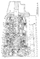
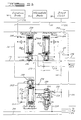
- Figure 1 is a cross section of a transmission according to this invention showing in the assembled condition a hydrokinetic torque converter, the clutches, brakes and gear units.
- Figures 2a-2h are diagrams of the multiple-speed transmission showing in heavy lines the components that operate to produce each of the various speeds.
- Figure 3 is a table showing the engaged and disengaged states of hydraulic clutches and brakes and the driving and overrunning states of the overrunning clutches for each speed and range in which the transmission can operate.
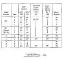
- Figure 4 is a table showing the states of solenoid-operated shift valves, a converter clutch valve and coast clutch valve for each speed and range of the transmission.
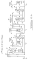
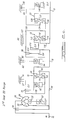
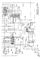
- Figures 5a-5e show a hydraulic control system capable of engaging and disengaging the hydraulic clutches and brakes of the transmission of Figure 1. The lines connecting the hydraulic components are labeled alphanumerically to indicate the hydraulic pressures in the lines for each speed and range.
- Referring first to Figure 1, one end of an
engine crankshaft 10 is driveably connected through the transmission to the poweroutput tail shaft 12, which is adapted to be connected to the vehicle traction wheels through differential, driveline, and axle assemblies. The main transmission housing 22 encloses simpleplanetary gear units Transmission housing 22 is bolted at its left-hand periphery to the cylinder block of an internal combustion engine and, at its right-hand end, to the left-hand end of tail shaft extension housing 24, which surroundsoutput shaft 12. - Transmission housing 22 encloses a
hydrokinetic torque converter 26, which includes abladed impeller 28, abladed turbine 30 and abladed stator 32. The impeller, the turbine and the stator are arranged in fluid flow relationship in a common toroidal circuit. The impeller includes a housing connected driveably to driveplate 34, which is bolted to the end ofcrankshaft 10.Turbine 30 includes a turbine hub 36 splined toturbine shaft 38.Impeller 28 is connected to impeller housing 40, which is journalled for rotation on a portion 42 of apump housing 44, which closesconverter housing 22.Pump housing 44 is bolted totransmission housing 22 and encloses gear elements of a positive fixeddisplacement pump 46, which serves as a pressure source for the control valve system to be described with reference to Figures 5a-5e. Astator sleeve shaft 48 extends frompump housing 44 and supports the inner race 50 of a one-way clutch 52 whose outer race supportsstator 32. - A torque
converter lockup clutch 54 is splined at 56 to the turbine hub 36 and carries afriction surface 58, located at its radially outer end, to driveably engage thetorque converter cover 61, welded to the impeller housing.Lockup clutch 54 is closed, locked, applied or engaged to complete a mechanical connection between the impeller and turbine when pressurized hydraulic fluid, contained in the torque converter casing,forces friction surface 58 against the housing. The torque converter is opened, unlocked, released or disengaged so that a hydrodynamic driving connection exists between the impeller and turbine when pressurized hydraulic fluid is supplied throughpassage 63 betweenconverter cover 61 andfriction surface 58 of thelockup clutch 54 to disengage these surfaces. -
Turbine shaft 38 is splined at 58 to thecarrier 60 of the firstplanetary gearset 16, which includessun gear 62, a set ofplanetary pinions 64 rotatably supported oncarrier 60 andring gear 66. Sungear 62 is driveably connected to amember 70 that is common to acoast clutch 72 and anoverdrive brake 74.Ring gear 66 is driveably fixed to a drum portion 68 connected tointermediate shaft 76. -
Overdrive brake 74 includes a set of clutch discs fixed totransmission housing 22, aload block 78 fixed totransmission housing 22, a set of clutch discs driveably connected to the outer surface ofclutch member 70 and interposed between the discs affixed to the transmission housing, aclutch piston 80 displaceable hydraulically against the clutch disc assembly andhydraulic cylinder 82 containingclutch piston 80, and a Belleville spring 84 for returningclutch piston 80 to the inactive position when hydraulic pressure is removed fromcylinder 82. -
Coast clutch 72 includes a set of clutch discs driveably connected to the inner surface ofclutch member 70, a load block connected to the inner surface ofclutch member 70, a second set of clutch discs driveably fixed toring gear 66,piston 86 actuated hydraulically to engage the coast clutch disc sets, ahydraulic cylinder 88 within whichpiston 86 moves, and a Belleville spring 90 to returnpiston 86 to the disengaged position when hydraulic pressure is removed fromcylinder 88. - A first one-
way clutch 92 has its outer race driveably connected toring gear 66, its inner race driveably connected by a spline tocylinder 88 and tosun gear 62 and a driving member located in the annulus between the inner and outer races for producing a one-way driving connection therebetween. A second one-way clutch 94 is located betweenintermediate brake 96 anddirect clutch 98. One-way clutch 94 includes an outer race that carries a set of brake discs for theintermediate brake 96, an inner race driveably fixed todrum 100, and a driving member located in the annular region between the inner and outer races for producing a one-way drive connection therebetween. -
Intermediate brake 96 includes a second set of brake discs fixed totransmission housing 22, a load block fixed to thetransmission housing 22, a piston 101 actuated hydraulically to force the brake disc sets into drivable relationship against the load block,hydraulic cylinder 83 within which piston 101 moves and a Belleville spring. -
Drum 100 is stopped and held against thetransmission housing 22 through the action of anintermediate brake band 102 actuated by a hydraulic intermediate servo. Direct clutch 98 operates to produce a drive connection betweendrum 100 andclutch member 104. The direct clutch includes a first set of clutch discs splined to the inner surface ofdrum 100 and a second set of clutch discs connected toclutch member 104, and interposed between successive members of the first clutch disc set. Apiston 106 moves within a hydraulic cylinder to force the clutch disc sets into drivable connection against the load block that is carried on the inner surface of thedrum 100. Piston 106 moves within the hydraulic cylinder defined bydrum 100 and is restored to its disengaged position through operation of acoil compression spring 108. - Forward clutch 110 operates to produce a driving connection between
clutch member 104 and thering gear 112 of the secondplanetary gearset 18. This gearset includes asun gear 114, a set ofplanetary pinions 116 in continual meshing engagement withsun gear 114 andring gear 112, rotatably supported on acarrier 118 which is driveably connected by spline 120 to thetail shaft 12. -
Forward clutch 110 includes a first set of clutch discs driveably connected to the inner surface ofclutch member 104 and a second set of clutch discs, each interposed with discs of the first set, driveably connected to the outer surface ofring gear 112. Piston 122 is hydraulically actuated for movement within the cylinder defined byclutch member 104 to force the clutch discs into a drivable connection. Bellevillespring 124 returns piston 122 to the disengaged position when hydraulic pressure is removed from the clutch cylinder. - The third
planetary gearset 20 includessun gear 126 formed integrally withsun gear 114,ring gear 128 connected byspline 130 totail shaft 12, a set ofplanet pinions 132 rotatably supported oncarrier 134, which is driveably connected to a first set of brake discs of the low-and-reverse brake 136. A second set of brake discs ofbrake 136 is fixed totransmission housing 22; each disc of the second set is interposed between successive discs of the first disc set ofbrake 136. Brakepiston 138 is actuated hydraulically whencylinder 140 is pressurized to force the piston against the first and second brake disc sets and to produce a drivable connection therebetween against the effect of thereturn spring 142, which forcespiston 138 to the brake disengaged position whencylinder 140 is vented.Load block 144, fixed to the transmission casing reacts the force applied bypiston 138 to the disc brake sets. - A one-
way brake 146 includes an outer race pinned tocarrier 134, an inner race 150 bolted to thetransmission housing 22, and a driving member located in the annular region between the inner and outer races to produce a one-way drive connection betweencarrier 134 and the casing. - The transmission produces four forward gear ratios and a reverse gear. The three lowest of the forward gear ratios are produced both automatically and by manual operation of the gear selector lever by the vehicle operator. The third forward gear ratio directly connects the
engine crankshaft 10 tooutput tail shaft 12, and the fourth forward ratio is an overdrive ratio. When the gear selection is made manually by the vehicle operator, the three lowest forward gear ratios and the reverse drive involve the engagement of coast clutch 72, and through its operation, the engine braking effect is transmitted through the transmission to theoutput tail shaft 12. Figure 3 shows engaged and release conditions of the clutches and brakes and driving and overrunning conditions of the one-way clutches for each of the gears and ranges of the transmission. - The gear selector lever includes a PRND21 switch, which produces an electrical signal, preferably a voltage, whose magnitudes represent each of the PRND21 positions. The gear selector and the manual valve it controls can be moved among the following alphanumeric positions from leftmost to rightmost: P for park, R for reverse, N for neutral, D for overdrive, 2 for manually selected second gear, and 1 for manually selected first gear. When the gear selector is in the D position and an overdrive cancel button is depressed, a mechanically selected condition called "drive" range, the transmission will produce only the three lowest gears. When the button is released, and the selector is in the D position, a condition called "overdrive" range, the transmission can produce four forward gears. When the gear selector is moved to the manual 1 or 2 positions, the transmission produces only the first or second gear ratios, respectively.
- Coast clutch 72 produces engine braking in third gear when the gear selector is in "drive". Otherwise, the transmission would freewheel in third gear while the vehicle is coasting. When overdrive range is selected,
coast clutch 72 is disengaged hydraulically but engine braking results in fourth gear through operation ofoverdrive brake 74. When manual 2 andmanual 1 are selected, the coast clutch is applied hydraulically through operation of aclutch shift valve 302; whereas, when drive is selected, the coast clutch shift is actuated through operation of a solenoid-actuated coast clutch valve controlled by programmed logic. A manually initiated shift from fourth gear to third gear or second gear causes a short delay to allow overdrive clutch 74 to release fully before coast clutch 72 engages. - To prevent
intermediate band 102 from absorbing excessive driveline energy in themanual 2 and manual 1 ranges, application ofband 102 is delayed until the coast clutch engagement is inferred by expiration of a shift-in-progress timer. - The torque flow in each gear and range is described next with reference to Figures 2a-2h.
- Low speed forward drive acceleration in the automatic mode is obtained by engaging forward clutch 110. Torque then is delivered from
turbine shaft 38 tocarrier 60 of thefirst gearset 16. One-way clutch 92 driveably connectsring gear 66 andsun gear 62 so that theentire gearset 16 turns as a unit and drivesintermediate shaft 76. Torque is then delivered fromintermediate shaft 76 to thering gear 112 through engaged forward clutch 110, thus imparting a driving torque tocarrier 118 and the poweroutput tail shaft 12. The reaction torque on sun gears 114, 126 is in a reverse direction. This causes a forward driving torque onring gear 128, which is transferred to theoutput tail shaft 12 becausecarrier 134 acts as a reaction member.Carrier 134 is held against rotation in this instance by one-way brake 146. - In coasting operation, i.e. when torque flow is from
output tail shaft 12 towardturbine shaft 38,OWB 146 overruns so that there is no torque path to the torque converter. - The vehicle operator selects low speed operation manually by moving the gear selector lever to the 1 position. In this range, forward clutch 110, reverse-
low brake 136 and coast clutch 72 are engaged, butconverter lockup clutch 54 is always disengaged.Clutch 72 connectsring gear 66 andsun gear 62, sogearset 16 again turns as a unit and drivesshaft 76.Shaft 76 drives clutch 110, which drivesring gear 112 andcarrier 118.Brake 136 provides the reaction by holdingcarrier 134 against rotation. - In coasting operation, the torque flow is from
shaft 12 toshaft 76. A drive connection toengine shaft 10 for engine braking effect is completed fromshaft 76 bycoast clutch 72 andtorque converter 26.Clutch 72 is applied with the logic of the hydraulic circuit of Figures 5a-5e. - Second speed ratio acceleration is achieved automatically by maintaining the first gear status of the friction elements and by engaging
intermediate brake 96. This holds sun gears 114, 126 against rotation because overrunning clutch 94 driveably connectsbrake 96 to drum 100. Powerflow from the engine to ringgear 112 is the same as that for the first speed overdrive and drive ranges. Planet pinions 116 are driven byring gear 112 and rotate withcarrier 118 aboutsun gear 114.Ring gear 112 continues to act as a power input element andcarrier 118 continues to drive theoutput tail shaft 12. Overrunningbrake 146 freewheels so that all of the torque multiplication is accomplished bygearset 18. - During coasting,
shaft 12drives carrier 118 andpinion 116.Ring gear 112 and clutch 110 rotating at enginespeed cause OWC 94 to freewheel in the coast direction, so the torque path ends there. - In the manually selected second speed, the following friction elements are engaged: coast clutch 72,
intermediate brake 96, forward clutch 110 andintermediate band 102. In driven operation, clutch 72 connectsring gear 66 andsun gear 62, sogearset 16 turns as a unit and drivesshaft 76.Shaft 76drives ring gear 112 throughclutch 110. Overrunning clutch 94 driveably connects sun gears 114, 126 tointermediate brake 96, which holdssun gear 114; therefore, pinions 116 are driven byring gear 112 and rotate withcarrier 118 aboutsun gear 114.Brake 96 is engaged beforeband 102 is applied, as will be explained below, so full engine torque is not carried solely byband 102 but is stored withbrake 96. - In coasting operation, clutch 94 overruns and
shaft 12drives carrier 118 andpinions 116 aboutsun gear 114, which is held byband 102.Ring gear 112 drivesshaft 76 andring gear 66 throughforward clutch 110.Gearset 16 turns as a unit becausecoast clutch 72 connectsring gear 66 tosun gear 62. Therefore, pinions 64 andcarrier 60drive turbine shaft 38, which is connected by theconverter 26, or byconverter clutch 54, toengine shaft 10. - While accelerating in the overdrive range, third gear ratio results by maintaining forward clutch 110 and
intermediate brake 96 engaged and by engagingdirect clutch 98. When the engine drivesoutput shaft 12, overrunningbrake 146 and overrunning clutch 94 freewheel, but one-way clutch 92 drives.Shaft 76 andturbine shaft 38 turn at the same speed. One-way clutch 92 driveably connectsring gear 66 andsun gear 62 so thatturbine shaft 38 is driveably connected by thefirst gearset 16 tointermediate shaft 76. Direct clutch 98 and forward clutch 110 driveablyconnect ring gear 112, sun gears 114, 126 andintermediate shaft 76, which rotate as a unit. Planet pinion set 116,carrier 118 andoutput shaft 12 are driven at the speed of theturbine shaft 38 because of the connection betweenring gear 112 andsun gear 114. Overrunningbrake 146 freewheels. When the vehicle coasts,OWC 92 freewheels; therefore,ring gear 66 andsun gear 62 are disconnected and no engine braking effect occurs. - When the overdrive cancel switch is closed on the gear selector to place the transmission in the drive range, the friction elements operate as they do to produce third gear in the overdrive range except that
coast clutch 72 is engaged. The transmission produces a direct connection betweenturbine shaft 38 andoutput tail shaft 12, as in third gear overdrive, except that clutch 72 connectsring gear 66 andsun gear 62 instead ofOWC 92. - When the vehicle coasts, clutch 72 remains engaged,
gearset 16 driveably connectsshafts turbine shaft 38 toengine shaft 10. - The fourth gear ratio is achieved by maintaining forward clutch 110,
direct clutch 98 andintermediate brake 96 engaged and by engagingoverdrive brake 74.Sun gear 62 ofgearset 16 is held against rotation bybrake 74 and one-way clutch 92 freewheels due to the engagement of overdrive brake. In this instance,ring gear 66 andintermediate shaft 76 are driven at a higher speed thanturbine shaft 38 andcarrier 60. Gearsets 18 and 20 are disposed in the same condition as they were for the third gear ratio in the automatic mode; therefore, the speed of theoutput tail shaft 12 is the same as the speed of theintermediate shaft 76. - In coasting operation,
overdrive brake 74 remains engaged and the torque path fromoutput tail shaft 12 toengine shaft 10 is completed bygearset 16 and the torque converter. Engine braking is therefore operative. - Reverse drive is achieved by releasing
intermediate brake 96, forward clutch 110 andoverdrive brake 74 and by applying low andreverse brake 136, direct clutch 98, andcoast clutch 72. With the friction elements so disposed, one-way clutch 94 freewheels, one-way clutch 92 is inactive and one-way brake 146 is inactive. Coast clutch 72 driveably connectssun gear 62 andring gear 66 of thefirst gearset 16 so that turbine torque is delivered fromshaft 38 directly to sun gears 114, 126. Withcarrier 134 acting as a reaction point,ring gear 128 and poweroutput tail shaft 12 are driven in a reverse direction. - The transmission will produce upshifts and downshifts among the three lowest gear ratios in the drive range, and among all four gear ratios in the overdrive range. Engine braking occurs in the highest gear available in each range, i.e., 1, 2, drive and overdrive. The schedule of Figure 4 shows the status of the coast clutch solenoid in each gear of each range and the availability of engine braking.
- Figures 5a through 5e show the hydraulic control valve system that controls application and release of the hydraulic clutches and brakes of the change-speed gear box of Figures 1 and 2. The various passages are pressurized in accordance with selected positions of a manual valve 160, moved manually by the vehicle operator among six positions P, R, N, D, 2 and 1, and states of certain solenoid-operated valves as determined by microprocessor execution of control algorithms.
- Fluid required for the operation of the hydraulic control valve system is supplied at the output of a hydraulic pump, which is supplied from the sump or reservoir of the transmission through a filter or from a return line connected to the inlet of the pump. The pump may be a fixed displacement pump that produces a flow rate proportional to its speed.
- Line pressure magnitude is controlled by
main regulator valve 162 shown in Figure 5a. This valve operates in response to control pressure carried inline 164 fromTV pressure valve 166.Valve 166 is connected bypassages main regulator valve 162. Avariable force solenoid 172 regulates TV pressure by having applied across its winding an electrical voltage duty cycle in accordance with the control of the microprocessor output. Hydraulic pressure having a magnitude between 0,35 Kg/cm² (5 psi) and 5,95 kg/cm² (85 psi) produced byvalve 166 is applied to the end ofline regulator valve 162. When there is demand for a high volume of fluid at line pressure,spool 172 moves downward due to TV pressure operating against the effect of a set ofcoil springs 174, closes the return line to the suction side of the pump, and closes torqueconverter charge line 176. Then substantially the entire volumetric flow of the pump is carried inpassage 170. - The magnitude of pressure in
line 170 is a result of upwardly directed differential pressure on the lower end ofspool 172 acting against the spring forces and a TV pressure force directed downward on the spool. When line pressure is high in relation to TV pressure,spool 172 moves upward and opens the feedback line to the suction side of the pump. Before this occurs, however,line 176 toconverter regulator valve 178 is opened. Thus, line pressure is regulated by balancing the spring forces and TV pressure against line pressure inpassage 170. - When manual valve 160 is moved to the 1 and R positions, line pressure is carried in
passages 180, 182 to a differential pressure area of the main regulator valve. The pressure developed on the differential area operates to forcespool 172 downward so that line pressure is higher when the reverse and 1 ranges are selected than for any of the other settings of the gear selector and manual valve. Higher line pressure in these ranges increases the torque capacity of the clutches and brakes engaged to produce the first gear and reverse drive while engine torque is near its peak magnitude. -
Passage 170 carries line pressure to solenoidregulator valve 184, which produces a regulated solenoid feed pressure carried inpassage 186 to first and second solenoid-operatedshift valves valve 192, and coast clutch solenoid-operatedfeed valve 194.Solenoid regulator valve 184 maintains the output inline 186 at approximately 3,5Kg/cm² (50 psi) by balancing spring force applied to the spool against an opposing line pressure force on the spool end resulting from feedback output. -
Valves line 186 andoutput lines valve 188 is deenergized,line 196 is vented by being connected to the low pressure sump. But when the solenoid is energized,solenoid feedline 186 is connected toline 196. Similarly,valves solenoid feedline 186 tolines -
Converter clutch 54 is engaged to locktorque converter 26 by pressurizingline 204 and ventingline 206. The converter clutch is disengaged and the torque converter opened whenline 206 is pressurized andline 204 is vented. Converterclutch control valve 208 moves upward within the valve body due to a force onspool 210 resulting from converter clutch solenoid pressure carried inline 200.Valve 208 is forced downward by thehelical spring 211 and a pressure force resulting from 1-R pressure carried inline 180 to the upper end ofspool 210.Control valve 208 is supplied through line 212 with regulated converter feed pressure fromconverter regulator valve 178, which regulates converter feed pressure in line 212 by sensing the pressure in line 212 and throttling converter feed pressure inline 176. When converterclutch solenoid valve 192 is energized,line 200 is pressurized, andspool 210 moves upward against the force of thespring 211 to connectlines 212 and 204. When this occurs,line 206 is connected byvalve 208 to ventport 214 andconverter clutch 54 is engaged. - When
solenoid valve 192 is deenergised,line 200 is vented causingspool 210 to move downward, closing the connection betweenlines 212 and 204, closing the connection ofline 206 to vent 214, and opening a connection betweenlines 212 and 206. This ventsline 204 throughvalve 208 and a hydraulic fluid cooler to the sump of the transmission. This action opens the torque converter by disengaging the mechanical connection ofimpeller 28 andturbine 30 made throughclutch 54. The 1-R pressure, in addition to increasing line pressure for a given TV pressure, as described with respect to the operation ofvalve 162, also operates to open the torque converter ifsolenoid valve 192 remains open while the gear selector is moved to the 1 or R positions, perhaps due to failure of the solenoid that operatesvalve 192, a short circuit or other electrical fault. This 1-R pressure assures the torque converter will be open if the gear selector is located in the R and 1 positions so that the torque multiplication effect of the converter is available to maximize torque tooutput tail shaft 12.Converter regulator valve 178 limits torque converter feed pressure to approximately 7,7 Kg/cm² (110 psi.) -
Line modulator valve 220 is connected to regulated line pressure bypassages passages - Regardless of whether the OD cancel button is depressed on the gear selector mechanism, whenever manual valve 160 is moved to the D position, the position shown in Figure 5d, regulated line pressure in
passage 168 is connected through valve 160 topassage 226. Forward clutch 110 is continually connected to regulated line pressure throughpassage 226, orifice 342 and passage 242; provided the manual valve is in a forward drive position. First gear results for automatic shifting when the forward clutch alone is engaged in this way. - In the D range and with the transmission operating in first gear, first
solenoid shift valve 188 directs SOL1 pressure to 1-2shift valve 228 throughpassage 196 and to 2-3 shift valve 232 throughpassage 244, but secondsolenoid shift valve 190 is exhausted. Therefore, shiftvalves 228 and 232 are moved by SOL1 pressure to the rightward extremity, closingline pressure passages - An upshift to second gear occurs while first
solenoid shift valve 188 remains open and after secondsolenoid shift valve 190 is opened.Valve 190 directs SOL2 pressure throughpassage 198 to the end of 3-4shift valve 236 and tomanual timing valve 306.Passage 198 also directs SOL2 pressure toshuttle valve 246. Ifpassage 372 is not pressurized,valve 246 directs SOL2 pressure tomanual transition valve 250. If L/Rclutch pressure passage 320 is not pressurized,transition valve 250 directs SOL2 pressure to the spring end of 1-2shift valve 228 through line 252. The 1-2 shift valve is moved leftward by SOL2 pressure, thereby opening the connection betweenpassages intermediate brake accumulator 256. -
Line modulator valve 220 andaccumulator 256 work cooperatively to supply pressurized fluid tointermediate brake 96 thereby engaging second gear.Line modulator valve 220 supplies TVLM pressure tointermediate brake accumulator 256, overdriveclutch accumulator 260, and directclutch accumulator 262. Each accumulator is shown with its plunger located as it is prior to an upshift and filled with hydraulic fluid supplied fromvalve 220. -
Valve 258, located immediately aboveaccumulator 256, balances the spring force against intermediate brake pressure and moves upward connectingpassages accumulator 256 is filled throughorifice 264. The orifice establishes a constant pressure drop and flow rate into the upper end of the accumulator cylinder and moves the plunger downward at a rate consistent with the flow rate throughorifice 264 against the force of the springs within the accumulator and TVLM pressure within the accumulator below the plunger. In this way, the pressure inpassage 261 rises linearly and rapidly whenvalve 258 first opens; thereafter, pressure inbrake 96 increases linearly as time increases at a lower rate determined by the flow rate throughorifice 264 and the spring constant of the springs within the accumulator. Also, pressure inbrake 96 has a magnitude for each unit of elapsed time that varies with TV pressure, as is explained below. - The output of
valve 220 is TVLM pressure supplied to the space within each of the accumulators below the plungers.Spool 266, located at the top of the bore ofline modulator valve 220, regulates by balancing TVLM pressure against the force of the inner isolator spring 268, a short spring having a relatively high spring rate that prevents contact betweenspools passages VFS valve 166, is approximately 0,42 Kg/cm² (6 psi) or lower,spool 270 is held by the outer spring at the lower end of the valve bore, and spring 268 does not touchspool 266. In this range of TV pressure,passage 272 is vented through port 269 because feedback TVLM pressure will have forcedspool 266 downward closing communication betweenpassages 222 and 272. When TV pressure rises above 0,42 Kg/cm² (6 psi),valve 270 rises off its seat against the effect of the outer spring. Spring 268 causes spool 266 to regulate because it movesspool 266 upward causing TVLM pressure to rise by one unit for each two unit increase of TV pressure above 0,42 Kg/cm²(6 psi). In this way, line pressure is modulated according to the magnitude of TV pressure produced byVFS valve 166 in accordance with the control of the microprocessor. - Accordingly, the pressures produced by
accumulators passages - During the upshift, TVLM pressure in
line 272 remains substantially constant because fluid forced from below the accumulator plunger briefly and slightly raises the pressure force at the head ofvalve 266 and opens the connection betweenline 272 and the vent 269 inmodulator valve 220. Then the pressure inline 272 falls and the opening to vent 269 closes. This lost fluid is returned to the accumulator through line 222 while the accumulator is being recharged. When the intermediate brake is to be disengaged, for example, during a 2-1 downshift, the process for activating the accumulator is substantially reversed from that of the upshift. The 2-1 downshift occurs whenline 254 is vented at 384 through 1-2shift valve 228 due to the presence of SOL1 pressure and the absence of SOL2 pressure at that shift valve. Flow from the space above the plunger ofaccumulator 266 throughorifice 275 and the constant spring rate of the accumulator springs again controls the rate at which the plunger rises within its chamber and the rate at which the accumulator cylinder below the plunger is filled with fluid from line 222 andline modulator valve 220. As the accumulator is being recharged, fluid within the accumulator cylinder above the plunger flows through one-way check valve 274, andpassages Check valve 277 directs fluid through 2-1 downshift orifice, and the fluid is vented through 1-2shift valve 228. Likewise,intermediate brake 96 is vented throughpassages valve 228. -
Intermediate brake 96 remains engaged for third gear and fourth gear during automatic operation because 1-2shift valve 228 connectspassages solenoid valves - Overdrive
clutch accumulator 260 works, asaccumulator 256 does, to pressurize and vent overdrive clutch 74 throughpassage 276 during a 3-4 upshift and 4-3 downshift. These upshifts and downshifts are initiated by selectively pressurizing and ventingpassage 278 through 3-4shift valve 236, as described below. - An automatic upshift from second gear to third gear occurs after first
solenoid shift valve 188 is closed by deenergizing its solenoid, and maintainingsecond solenoid valve 190 open, according to the schedule of Figure 4. Line pressure continues to be directed by manual valve 160 throughpassages passage 280 through whichcontrol valve 282 at the end of directclutch accumulator 262 is pressurized. Direct clutch 98 is thereby pressurized rapidly over a first, short portion of its engagement period, during which the clearances among the various components of the clutch are taken up. Thereafter, clutch 98 is pressurized at a linearly increasing pressure controlled by the magnitude of TVLM, the rate of flow through orifice 284, and the spring constant ofaccumulator 262, as has been previously described with respect toaccumulator 256, until the clutch is fully engaged.Clutch 98 remains engaged during third gear and fourth gear operation because SOL1 pressure is absent; therefore, 2-3 shift valve 232 maintains open the connection between line pressure andaccumulator valve 282. - An automatic 3-2 downshift occurs when
solenoid valves passage 286,valve 282,passage 280,orifice 283, shift valve 232,passage 290, 3-4shift valve 236, andpassage 292 to sump through manual valve 160. This path to sump from the direct clutch is continually open through the 3-4shift valve 236 regardless of the presence or absence of SOL2 pressure atvalve 236. - An automatic upshift from third gear to fourth gear results when
solenoid valves overdrive brake 74 is engaged. When this occurs, 3-4shift valve 236 is moved by its spring to the position shown in Figure 5d, whereby line pressure from the manual valve is directed bypassage 234 through the shift valve topassage 278.Control valve 286 at the end ofoverdrive accumulator 260 is moved by its spring downward so thatbrake 74 is pressurized throughpassage 276 rapidly during the first, short phase of engagement of the brake during which clearances among the components of a brake are taken up. Thereafter, pressure inbrake 74 rises linearly with time according to the control of TVLM pressure, the flow rate of fluid throughorifice 288 and the spring constant of the accumulator, as has been described with respect toaccumulator 256. - An automatic downshift from fourth gear to third gear occurs when
SOL 2 pressure is applied to shiftvalve 236. This action moves the valve rightward opening a connection throughpassage 278,valve 286,passage 276 andbrake 74 to the vent port atshift valve 236. - When manual valve 160 is moved to the R position, line pressure in
passage 168 is directed topassage 180, throughbypass loops passage 292, andpassage 226 is closed to the source of line pressure. Thus, forward clutch 110 is disengaged.Solenoid valve 188 is opened to connectSRV passage 186 toSOL1 passage 196, butsolenoid shift valve 190 is closed. SOL1 pressure is carried inpassage 244 to the end of 2-3 shift valve 232, and to the SOL1 port of 1-2shift valve 228. -
Passage 180 is connected to line pressure both when the manual valve is moved to the R position and to the 1 position. 1-R pressure forces spool 210 of the converterclutch control valve 208 downward, thereby directing regulated converter pressure throughvalve 208 andpassage 206 to openconverter clutch 54. This action assures that, if SOL3 pressure, which is limited to 50 psi, remains on while the gear selector or manual valve is in the 1 or R position, there is sufficient pressure to pushspool 210 downward and open the torque converter. In this way, the torque converter is opened when 1 or R positions are selected so that the torque multiplication capacity of the torque converter is available during these high torque conditions. Passage 182 carries line pressure fromvalve 208 to themain regulator valve 162 when the gear selector is in the 1 and R positions. This forcesspool 172 downward, closes return to the pump inlet, and directs more pump output topassage 170. -
Passage 300 and one-way check valves 299, 301 direct 1-R pressure also to the end of coastclutch shift valve 302. Check valve valve 299 andpassage 304 carry 1-R pressure from the manual valve tomanual timing valve 306. - Because SOL2 pressure is absent, 3-4
shift valve 236 is in the position shown in Figure 5d. Therefore, when the manual valve is moved to the R position,shift valve 236 connects line pressure inpassage 292 topassages Check valve 312 directs R pressure throughorifice 314 to the end of low/reverse modular valve 316, where a pressure force acting on the valve in opposition to its spring, opens R pressure inpassage 318 to low/reverse brake passage 320. Low/reverse brake 136 is the first friction element to become engaged in the process of producing reverse drive. - The 3-4
shift valve 236 also connects R pressure inpassage 318 to coastclutch shift valve 302 throughpassage 322. Control pressure to coastclutch shift valve 302 is directed frompassage 300 through thecheck valve 301 topassage 324.Valve 302 moves leftward against the effect of its spring due to 1-R control pressure and completes the connection frompassage 322 to passage 326 and passage 331 tocoast clutch 72, which is the second friction element applied during reverse drive engagement. - When the manual valve is in the R position, 1-2
shift valve 228 connectspassages Manual timing valve 306 includes a first piston 361, which is forced into contact withretainer plate 363 by SRV pressure forwarded fromsolenoid regulator valve 184 and maintained at a constant pressure by that valve. Asecond piston 330 is biased by a spring into contact also withretainer plate 363. First andsecond inlet passages 360, 362 supply 1-R/MAN2 pressure tomanual timing valve 306 frompassage 304. Anorifice 364, located in second inlet, passage 362, controls the flow rate through that passage and throughtiming valve 306 during a portion of its operation. Thereafter, when the valve opens, the higher pressure infirst inlet passage 360 is directed to outlet passage 366. - In operation, first piston 361 is forced by SRV pressure into contact with
retainer plate 363.Second piston 330 is forced by the spring into contact with theretainer plate 363 against feedback pressure inpassages 366, 368 tending to holdsecond piston 330 rightward. This closespassage 360 but permits flow throughorifice 364 and passage 366 tofeedback passage 368.Ball check valve 369 andpassage 332 carry R pressure from 1-2shift valve 228 totiming valve 306, butball check valve 369 closespassage 332 when it is at a higher pressure thanpassage 310. Therefore, R pressure inpassage 332 is directed by timingvalve 306 immediately without delay topassage 336 because R pressure forcessecond piston 330 rightward and opens this connection. - The space immediately adjacent both sides of the
retainer plate 363 is pressurized throughfeedback passage 368. Because of the differential pressure across its ends, first piston 361 immediately moves for a short period away from the plate against SRV pressure until first piston 361 seats on the valve body at the left-hand extremity. After this occurs, pressure rises quickly in the annulus, within which the retainer plate is located, andsecond piston 330 moves rightward, subject to the flow rate acrossorifice 364, against the spring force, until it becomes seated at the right-hand end of the valve chamber. In thisposition feedback passage 368 is open topassage 336, throughtiming valve 306 andfirst inlet passage 360 is open also topassages 336 throughpassages 366 and 368. The operation of thetiming valve 306, therefore, delays the occurrence of Delayed 1-R/MAN2 pressure at 2-3 shift valve 232 by the period while first piston 361 moves from the right-hand end of its chamber to the left-hand end plus the period whilesecond piston 330 moves rightward fromretainer plate 363 until timingvalve 306 opens. - Timing
valve 306 assures that whenever the vehicle operator moves manual valve 160 to the 1, 2 positions, a delay occurs before pressure from the manual valve is present at 2-3 shift valve 232. This produces a short delay, one or two seconds, before a downshift from third or fourth gear can be made into second gear. For example, when a 4-2 downshift is commanded by the vehicle operator by a manual shift to the 2 position at high speed, the transmission will dwell for a period, the period required for themanual timing valve 306 to produce MAN2 pressure in third gear, before the downshift to the second gear is completed. In third gear drive range, coast clutch engagement produces the engine braking effect, whereas in second gear manual operation,intermediate band 102 andservo 96 produce the engine braking effect. Torque capacity of the band and servo are much lower than torque capacity of the coast clutch. By avoiding an immediate high speed 4-2 downshift, torque loads eventually placed onband 102 are lower than otherwise they would be. Similarly, high speed downshifts into first gear are delayed to avoid the sensation of an abrupt downshift. - However, SOL2 pressure at the end of
timing valve 306 increases the delay, or the absence of SOL2 pressure prevents entirely any delay in pressure being output from timing 306, depending on the magnitude of 1-R/MAN2 pressure compared to SOL2 pressure, the force developed on the spring ofvalve 306, and the occurrence of SOL2 pressure. - When
second piston 330 is positioned at the right-hand end, pressure inpassage 332 is directed as R pressure topassage 336 and to ports of the 2-3 shift valve 232. Also, R pressure is present at 2-3 shift valve 232 at the end ofpassage 290. As a result of pressure inpassage 336, a differential pressure is developed on the spool of shift valve 232, which, regardless of the effect of SOL1 pressure at the end of the spool, forces the spool rightward against the effect of the spring to connectpassage 290 topassage 280.Control valve 282, at the end of the directclutch accumulator 262 is pressurized throughpassage 280 andcheck valve 338. In this way, application of direct clutch 98 is both controlled to rise linearly with time through operation ofaccumulator 262 and delayed with respect to engagement of lowreverse brake 136 andcoast clutch 72. When the direct clutch is fully engaged, reverse drive is completed. - R pressure from manual valve 160 is directed by
passages clutch valve 240. TV pressure also is directed throughpassage 340 from variableforce solenoid valve 166 tovalve 240. When TV pressure is high, as when transmission fluid is cold or the accelerator pedal is depressed substantially,valve 240 connectspassages valve 240 to flow fromaccumulator 262. - If the manual valve 160 is in the D position, and throttle pressure is high,
valve 240 moves leftward against the force of its spring and opens a connection between passage 238, which contains fluid at line pressure whenever the manual valve is in the D position, and passage 242 to the forward clutch. This action adds the flow of hydraulic fluid throughvalve 240 to the volume supplied throughpassage 226 and orifice 342 during automatic operation in forward drive. Therefore, when ambient temperature is low and the viscosity of the hydraulic fluid is relatively high, TV pressure increases the flow to the forward clutch and to the direct clutch to produce forward drive and reverse drive operation, respectively. - When first gear is produced manually by moving manual valve 160 to the 1 position, the transmission operates in the first gear by engaging forward clutch 110, low-
reverse brake 136 and coast clutch 72, opening firstsolenoid shift valve 188, and closing secondsolenoid shift valve 190. In this position, the manual valve 160 connectspassages bypass loops passages line pressure passage 168.Converter lockup clutch 54 is disengaged and the torque converter opens through operation of the converterclutch control valve 208,main regulator valve 162 andconverter regulator valve 178, as previously described with reference to reverse drive operation. - When
manual timing valve 306 times out,passage 336 communicates Delayed 1-R pressure to two ports of the 2-3 shift valve 232, which is moved rightward by the presence of SOL1 pressure at the lefthand end of the valve. This action opens communication betweenpassages shift valve 228. SOL1 pressure inpassage 196 moves shiftvalve 228 rightward, thereby connectingpassages Manual 1 pressure inpassage 352, is moved leftward by itsspring connecting passage 352 topassage 320, through which lowreverse brake 136 is engaged. - When the manual valve 160 is in the 1 position, it directs line pressure from
passage 168 throughpassage 226, orifice 342, and passage 242 to theforward clutch 110. - The
coast clutch 72 is energized through the manual valve 160, which directs line pressure throughpassage 180,check valves 299, 301 andpassage 324 to coastclutch shift valve 302. - Line pressure directed by manual valve 160 through
passages lines shift valve 236 produced by pressure inpassage 358 opens a connection betweenline passage 234 and coastclutch passage 322. Coastclutch shift valve 302 moves leftward due to the presence of 1-R pressure at its righthand end, and connectspassages 322 and 326 to coast clutch 72 throughorifice 374 and passage 331. Delayed 1-R pressure transmitted in passage 334 to 2-3 shift valve 232 is also passed through valve 232,passage 350, 1-2shift valve 228 andpassage 352 to low-reverse modulator 316. Low-reverse brake 136 is pressurized from valve 316, as is described above. - A manual shift to second gear results when the gear selector manual valve 160 is moved to the 2 position and both
shift solenoid valves passage 168 topassages passages passages 226, 242 and orifice 342. - The presence of SOL2 pressure at the end of 3-4
shift valve 236 moves the valve rightward to open the connection betweenpassage 234, which receives line pressure throughpassage 226, andpassage 322, which transmits line pressure fromshift valve 236 to coastclutch valve 302. Manual valve 160 directs MAN2 pressure throughpassages 372, direction valve 299,passage 300,direction valve 301 andpassage 324 to the control end of the coast clutch valve. The presence of the control pressure atvalve 302 opens a connection betweenpassages 322, 326 and directs coast clutch pressure throughorifice 374, and passage 331 tocoast clutch 72. - Whenever coast
clutch solenoid valve 194 is on, SRV pressure is connected throughvalve 194 topassage 202 anddirection valve 301 is pressurized, thereby closingpassage 300 and pressurizing the control port of coastclutch valve 302 throughpassage 324. This action, therefore, engages the coast clutch by completing a connection betweenpassages 322 and 326 regardless of the state of the manual valve. - MAN2 pressure is directed from manual valve 160 through
passage 372, direction valve 299 andpassage 304 topassages 360 and 362, which lead tomanual timing valve 306. When the delay period of the valve expires, MAN2 pressure is connected through the valve andpassages 334, 336 to the 2-3 shift valve 232. MAN2 pressure develops a differential pressure present at that shift valve, openspassage 230 topassage 358, which is closed at 3-4shift valve 236, and directs MAN2 pressure throughline 350 to 1-2shift valve 228. The 1-2manual transition valve 250, biased upward by its spring because of the absence of low-reverse brake pressure inpassage 371 and at its control port, directs MANS pressure to passage 252. MANS pressure adds to the effect of the spring atshift valve 228 and works in opposition to SOL1 pressure to moveshift valve 228 leftward, thereby closing the connection betweenpassages passages orifices intermediate servo 96.Orifices servo 97 so thatintermediate brake 96 is engaged shortly beforeservo 97, actuatesband 102 and holdsdrum 100 against rotation. With the 1-2 shift valve so disposed, line pressure inpassages shift valve 228 is connected bypassage 254 to the control valve at the end of intermediateclutch accumulator 256, by means of whichpassage 260 andintermediate brake 96 are pressurized in accordance with the technique described above. The delay in applyingservo 97 andband 102 until afterbrake 96 is applied assures that engine torque is not carried byband 100. - A manual downshift to first gear from second gear occurs after MAN2 pressure is removed from the control end of the 1-2 shift valve. This causes
shift valve 228 to move rightward thereby closing the connection betweenpassages intermediate servo 96, connectingpassages reverse brake 136 through the low reverse modulator valve 316, disconnectingpassages passage 254 to ventport 384. In this way,intermediate brake 96 is vented and drained throughaccumulator control valve 258. The fluid above the plunger ofaccumulator 256 passes through the 2-1 downshift orifice nearball check valve 277 inpassage 254 and eventually to vent 384. - When the manual valve is moved to the OD position and the drive button is depressed, the transmission will produce automatic shifts among the first three gears in the manner previously described with respect to automatic operation. However, in this case, unlike overdrive operation, third gear has engine braking effect due to engagement of the coast clutch.
Intermediate brake 96, direct clutch 98, and forward clutch 110 are applied as described above with respect to overdrive operation. To produce third gear, secondsolenoid shift valve 190 is on and firstsolenoid shift valve 188 is off. The 3-4shift valve 236, moved rightward by SOL2 pressure, opens a connection betweenpassage 234 and coast clutch pressure inpassage 322. - When a command is made for third gear operation and the manual valve is in the overdrive position with the drive range button depressed, coast
clutch solenoid valve 194 is on and it directs SOL4 pressure throughpassage 202.Check valve 301 pressurizes the control port of coastclutch shift valve 302. This movesshift valve 302 leftward and connects coast clutch pressure inpassage 322 to passage 326, through which coast clutch 72 is engaged, whereby the transmission is disposed for operation in third gear with engine braking. - To upshift from manual third gear to fourth
gear coast clutch 72 is disengaged and overdrive clutch 74 is engaged. To disengage the coast clutch, 3-4shift valve 236 moves leftward when SOL2 pressure is removed, thereby closing the connection between line pressure inline 234 andpassage 322 and connectingpassages Overdrive brake 74 is engaged through operation ofaccumulator 260. In this way, coastclutch shift valve 302 will not supply pressure to the coast clutch even if SOL4 pressure is available at the control port of coast clutch passage 326. In making the upshift from third gear manual to fourth gear, SOL4 pressure is removed permitting thevalve 390 to closepassage 322 and to connect coast clutch 22 to ventport 390.
Claims (8)
- A system for controlling the operation of a first friction element (72), comprising:
a source (46, 162) of regulated line fluid pressure;
manual valve means (160) moveable among positions (P, R, N, D, 2, 1) selected by an operator for connecting said line pressure source (46, 162) to a first port (226, 234) of the manual valve means (160) in accordance with a corresponding position (D) of the manual valve means (160);
a first control valve means (190) operated by a solenoid for producing a first control pressure (SOL2);
first shift valve means (236) connected to said first control pressure (SOL2) for connecting said first port (226, 234) of the manual valve means (160) to a first output port (322) of the first shift valve means (236) in accordance with the control of said first control pressure (SOL2);
second control valve means (194) operated by a solenoid for producing a second control pressure (SOL4);
second shift valve means (302) connected to said second control pressure (SOL4) for connecting said first output port (322) of the first shift valve means (236) to the first friction element (72) in accordance with the control of said second control pressure (SOL4);
characterized in that said manual valve means (160) further includes means (294, 295, 299) for producing a third control pressure (1-R/MAN2) concurrently with the connection it produces between said line pressure source (46, 162) and said first output port (226, 234) of the manual valve means (160);
means (301) for directing alternately said third control pressure (1-R/MAN2) or said second control pressure (SOL4) to said second shift valve means (302); and
said second shift valve means (302) is connected to the output (324) of said directing means (301) for connecting said first output port (322) of said first shift valve means (236) to said first friction element (72) in accordance with the control of the output (324) of the directing means (301). - The system of claim 1 wherein said second shift valve means (302) further includes means (326, 390) for alternately pressurizing (326) and venting (390) said first friction element (72) in accordance with the control of said second control pressure (SOL4).
- The system of claim 1 or claim 2 wherein said second control pressure (SOL4) is high or low pressure whose magnitude varies according to the energized or deenergized state of the solenoid that operates said second control valve means (194).
- The system of any of claims 1 to 3 wherein said manual valve means (160) further includes means (294) for connecting said line pressure source (46, 162) to a third control pressure (MAN2) output (372) of the manual valve means (160) when the manual valve means is positioned at a manually selected gear position (1).
- The system of any of claims 1 to 4 further comprising a second friction element (74) and wherein said first shift valve means (236) includes a second output port (278) connected to the second friction element (74) and means for connecting said first output port (226, 234) of said manual valve means (160) to said second output port (278) in accordance with the control of said first control pressure (SOL2).
- The system of claim 5 wherein said first shift valve means (236) further includes means for alternately pressurizing and venting said second friction element (74) in accordance with the control of said first control pressure (SOL2).
- A method for controlling the operation of a first friction element (72) in an automatic transmission that includes a source (46, 162) of regulated line fluid pressure, a manual valve means (160) moveable among positions (P, R, N, D, 2, 1) selected by an operator, comprising:
connecting said line pressure source (46, 162) to a first output port (236, 234) of said manual valve means (160) in accordance with a respective position (D) of said manual valve means (160);
producing a high pressure state and a low pressure state of a first control pressure (SOL2);
connecting said first output port (236, 234) of the manual valve means (160) to a first output port (322) of a first shift valve means (236) in accordance with the state of said first control pressure (SOL2);
producing a high pressure state of a second control pressure (SOL4) corresponding to manual valve positions (R,2,1) at which the gears are manually selected, and a low pressure state of a second control pressure (SOL4) corresponding to manual valve positions (D) at which the gears are automatically selected; and
connecting said first output port (322) of the first shift valve means (236) to said first friction element (72) in accordance with the control of said second control pressure (SOL4). - A method according to claim 7 for controlling the operation of a second friction element (74) and wherein a variable third control pressure (1-R/MAN2) corresponding to a requirement to pressurize said first friction element (72) is being produced and said second control pressure (SOL4) and said third control pressure (1-R/MAN2) are alternately directed to a second shift valve means (302), said first output port (322) of the first shift valve means (236) being connected to said first friction element (72) in accordance with the control of said second (SOL4) or said third control pressure (1-R/MAN2) directed to said second shift valve means (302).
Priority Applications (1)
| Application Number | Priority Date | Filing Date | Title |
|---|---|---|---|
| EP93105969A EP0559237B1 (en) | 1988-06-06 | 1989-04-07 | Four speed ratio automatic power transmission |
Applications Claiming Priority (2)
| Application Number | Priority Date | Filing Date | Title |
|---|---|---|---|
| US202746 | 1988-06-06 | ||
| US07/202,746 US4856383A (en) | 1988-06-06 | 1988-06-06 | Coast clutch control for multiple speed automatic transmission |
Related Child Applications (2)
| Application Number | Title | Priority Date | Filing Date |
|---|---|---|---|
| EP93105969A Division EP0559237B1 (en) | 1988-06-06 | 1989-04-07 | Four speed ratio automatic power transmission |
| EP93105969.5 Division-Into | 1993-04-13 |
Publications (3)
| Publication Number | Publication Date |
|---|---|
| EP0345433A2 EP0345433A2 (en) | 1989-12-13 |
| EP0345433A3 EP0345433A3 (en) | 1991-01-09 |
| EP0345433B1 true EP0345433B1 (en) | 1994-07-13 |
Family
ID=22751094
Family Applications (2)
| Application Number | Title | Priority Date | Filing Date |
|---|---|---|---|
| EP89106188A Expired - Lifetime EP0345433B1 (en) | 1988-06-06 | 1989-04-07 | Coast clutch control for multiple speed automatic transmission |
| EP93105969A Expired - Lifetime EP0559237B1 (en) | 1988-06-06 | 1989-04-07 | Four speed ratio automatic power transmission |
Family Applications After (1)
| Application Number | Title | Priority Date | Filing Date |
|---|---|---|---|
| EP93105969A Expired - Lifetime EP0559237B1 (en) | 1988-06-06 | 1989-04-07 | Four speed ratio automatic power transmission |
Country Status (4)
| Country | Link |
|---|---|
| US (1) | US4856383A (en) |
| EP (2) | EP0345433B1 (en) |
| JP (1) | JPH0226364A (en) |
| DE (2) | DE68926791T2 (en) |
Families Citing this family (8)
| Publication number | Priority date | Publication date | Assignee | Title |
|---|---|---|---|---|
| JPH01116347A (en) * | 1987-10-30 | 1989-05-09 | Nissan Motor Co Ltd | Control device for oil pressure of automatic transmission |
| JPH02173466A (en) * | 1988-12-26 | 1990-07-04 | Jatco Corp | Electronic speed change control device for automatic transmission |
| US5113725A (en) * | 1989-09-22 | 1992-05-19 | Toyota Jidosha Kabushiki Kaisha | Hydraulic control device of automatic transmission more smooth in low coast upshifting under under-D manual shift range |
| US5081886A (en) * | 1990-09-14 | 1992-01-21 | Ford Motor Company | Automatic transaxle control system for an automotive vehicle |
| US5036729A (en) * | 1990-10-23 | 1991-08-06 | Saturn Corporation | Coast-sync-coast downshift control method for clutch-to-clutch transmission shifting |
| JPH08184365A (en) * | 1994-12-28 | 1996-07-16 | Nippon Soken Inc | Automatic transmission for vehicle |
| US5642283A (en) * | 1995-10-27 | 1997-06-24 | Ford Motor Company | Multiple ratio transmission with swap-shift controls |
| JP3843488B2 (en) * | 1996-06-06 | 2006-11-08 | アイシン・エィ・ダブリュ株式会社 | Control device for automatic transmission |
Citations (1)
| Publication number | Priority date | Publication date | Assignee | Title |
|---|---|---|---|---|
| EP0179683A2 (en) * | 1984-09-18 | 1986-04-30 | Regie Nationale Des Usines Renault | Control device for an automatic transmission with four ratios |
Family Cites Families (16)
| Publication number | Priority date | Publication date | Assignee | Title |
|---|---|---|---|---|
| US3393585A (en) * | 1966-01-05 | 1968-07-23 | Ford Motor Co | Control system for a multiple speed ratio power transmission mechanism and semiautomatic and automatic ratio changing features |
| US3613484A (en) * | 1969-12-08 | 1971-10-19 | Ford Motor Co | Ratio shift timing valves for use in a control system for a multiple ratio automatic power transmission mechanism |
| US3714836A (en) * | 1971-02-16 | 1973-02-06 | Ford Motor Co | Automatic transmission controls for an automotive vehicle driveline |
| US3706240A (en) * | 1971-06-17 | 1972-12-19 | Ford Motor Co | Four-speed ratio automatic power transmission mechanism |
| JPS53123765A (en) * | 1977-04-05 | 1978-10-28 | Toyota Motor Corp | Overdrive device for automatic speed change gear |
| JPS54145859A (en) * | 1978-05-04 | 1979-11-14 | Aisin Warner | Automatic transmission with overdrive |
| JPS5560749A (en) * | 1978-10-28 | 1980-05-08 | Aisin Warner Ltd | Timing gear at the time of speed change in automatic speed change gear |
| JPS5547041A (en) * | 1978-09-30 | 1980-04-02 | Aisin Warner Ltd | Controller for automatic speed change gear |
| JPS55149454A (en) * | 1979-05-10 | 1980-11-20 | Aisin Warner Ltd | Automatic transmission controller |
| JPS5635845A (en) * | 1979-08-30 | 1981-04-08 | Aisin Warner Ltd | Overdrive device in automatic speed change gear |
| JPS56134656A (en) * | 1980-03-24 | 1981-10-21 | Aisin Warner Ltd | Controller for oil pressure of automatic transmission |
| US4776240A (en) * | 1982-02-04 | 1988-10-11 | Aisin Warner Kabushiki Kaisha | Automatic transmission |
| JPS61223362A (en) * | 1985-03-28 | 1986-10-03 | Honda Motor Co Ltd | Pressure oil flow rate controlling equipment for automatic gear |
| JPS61266857A (en) * | 1985-05-21 | 1986-11-26 | Toyota Motor Corp | Oil pressure control device of automatic speed change gear for car |
| JPS6241454A (en) * | 1985-08-15 | 1987-02-23 | Nissan Motor Co Ltd | Speed change control device for automatic speed change gear |
| US4744269A (en) * | 1986-11-06 | 1988-05-17 | Ford Motor Company | Automatic transmission with lockup converter clutch controls |
-
1988
- 1988-06-06 US US07/202,746 patent/US4856383A/en not_active Expired - Fee Related
-
1989
- 1989-04-07 DE DE68926791T patent/DE68926791T2/en not_active Expired - Fee Related
- 1989-04-07 EP EP89106188A patent/EP0345433B1/en not_active Expired - Lifetime
- 1989-04-07 EP EP93105969A patent/EP0559237B1/en not_active Expired - Lifetime
- 1989-04-07 DE DE68916709T patent/DE68916709T2/en not_active Expired - Fee Related
- 1989-05-17 JP JP1124094A patent/JPH0226364A/en active Pending
Patent Citations (1)
| Publication number | Priority date | Publication date | Assignee | Title |
|---|---|---|---|---|
| EP0179683A2 (en) * | 1984-09-18 | 1986-04-30 | Regie Nationale Des Usines Renault | Control device for an automatic transmission with four ratios |
Also Published As
| Publication number | Publication date |
|---|---|
| DE68926791D1 (en) | 1996-08-08 |
| EP0345433A2 (en) | 1989-12-13 |
| US4856383A (en) | 1989-08-15 |
| EP0345433A3 (en) | 1991-01-09 |
| EP0559237B1 (en) | 1996-07-03 |
| EP0559237A1 (en) | 1993-09-08 |
| JPH0226364A (en) | 1990-01-29 |
| DE68926791T2 (en) | 1997-02-27 |
| DE68916709T2 (en) | 1995-03-16 |
| DE68916709D1 (en) | 1994-08-18 |
Similar Documents
| Publication | Publication Date | Title |
|---|---|---|
| US4943921A (en) | Automatic transmission electronic gearshift control having altitude corrected shift criteria | |
| US4494423A (en) | Automatic transmission control for an automotive vehicle driveline having fail-safe logic | |
| EP0635662A2 (en) | Electronically controlled automatic transmission with failsafe pressure regulation | |
| US4884471A (en) | Four speed ratio automatic power transmission | |
| US4982622A (en) | Hydraulic pressure control device for automatic transmission | |
| US5389046A (en) | Automatic transmission control system | |
| US4876923A (en) | Torque converter lockup clutch control for an automatic transmission | |
| GB2037912A (en) | Device for controlling a lock-up clutch in an automatic transmission | |
| US4843917A (en) | Accumulator control for hydraulic actuating pressure of automatic transmission friction clutch or brake | |
| US4953091A (en) | Automatic transmission torque converter clutch control | |
| US5383825A (en) | Electronic shift controller for a multiple ratio automotive transmission | |
| US4748809A (en) | Hydraulic servo mechanism of automatic transmission for vehicle | |
| EP0559237B1 (en) | Four speed ratio automatic power transmission | |
| US4932282A (en) | Timing valve for manually selected gears of an automatic transmission | |
| US4858500A (en) | Apparatus for controlling lock-up clutch in automatic transmission system having main transmission and sub-transmission | |
| US5050460A (en) | Shift control system for automatic transmission | |
| GB2222644A (en) | Shift control system for automatic transmission | |
| US5016496A (en) | Shift control system for engine braking in an auxiliary transmission | |
| JP2786452B2 (en) | Hydraulic control unit for automatic transmission | |
| JPH023075B2 (en) | ||
| JPS6361541B2 (en) | ||
| JP2692243B2 (en) | Shift control method for automatic transmission for vehicle | |
| JPH0665908B2 (en) | Hydraulic control system for vehicle automatic transmission | |
| JPS6145147A (en) | Hydraulic controller of automatic speed changing gear of vehicle | |
| JPH0276967A (en) | Oil pressure control device for automatic speed change gear for vehicle |
Legal Events
| Date | Code | Title | Description |
|---|---|---|---|
| PUAI | Public reference made under article 153(3) epc to a published international application that has entered the european phase |
Free format text: ORIGINAL CODE: 0009012 |
|
| AK | Designated contracting states |
Kind code of ref document: A2 Designated state(s): DE FR GB |
|
| PUAL | Search report despatched |
Free format text: ORIGINAL CODE: 0009013 |
|
| AK | Designated contracting states |
Kind code of ref document: A3 Designated state(s): DE FR GB |
|
| 17P | Request for examination filed |
Effective date: 19910409 |
|
| 17Q | First examination report despatched |
Effective date: 19920930 |
|
| GRAA | (expected) grant |
Free format text: ORIGINAL CODE: 0009210 |
|
| AK | Designated contracting states |
Kind code of ref document: B1 Designated state(s): DE FR GB |
|
| REF | Corresponds to: |
Ref document number: 68916709 Country of ref document: DE Date of ref document: 19940818 |
|
| ET | Fr: translation filed | ||
| PLBE | No opposition filed within time limit |
Free format text: ORIGINAL CODE: 0009261 |
|
| STAA | Information on the status of an ep patent application or granted ep patent |
Free format text: STATUS: NO OPPOSITION FILED WITHIN TIME LIMIT |
|
| 26N | No opposition filed | ||
| PGFP | Annual fee paid to national office [announced via postgrant information from national office to epo] |
Ref country code: GB Payment date: 19970107 Year of fee payment: 9 |
|
| REG | Reference to a national code |
Ref country code: GB Ref legal event code: 746 Effective date: 19961213 |
|
| PGFP | Annual fee paid to national office [announced via postgrant information from national office to epo] |
Ref country code: FR Payment date: 19970421 Year of fee payment: 9 |
|
| PG25 | Lapsed in a contracting state [announced via postgrant information from national office to epo] |
Ref country code: GB Free format text: LAPSE BECAUSE OF NON-PAYMENT OF DUE FEES Effective date: 19980407 |
|
| PG25 | Lapsed in a contracting state [announced via postgrant information from national office to epo] |
Ref country code: FR Free format text: THE PATENT HAS BEEN ANNULLED BY A DECISION OF A NATIONAL AUTHORITY Effective date: 19980430 |
|
| REG | Reference to a national code |
Ref country code: FR Ref legal event code: D6 |
|
| PGFP | Annual fee paid to national office [announced via postgrant information from national office to epo] |
Ref country code: DE Payment date: 19980630 Year of fee payment: 10 |
|
| GBPC | Gb: european patent ceased through non-payment of renewal fee |
Effective date: 19980407 |
|
| REG | Reference to a national code |
Ref country code: FR Ref legal event code: ST |
|
| PG25 | Lapsed in a contracting state [announced via postgrant information from national office to epo] |
Ref country code: DE Free format text: LAPSE BECAUSE OF NON-PAYMENT OF DUE FEES Effective date: 20000201 |