EP0344967B1 - Apparatus for sensing sheets - Google Patents
Apparatus for sensing sheets Download PDFInfo
- Publication number
- EP0344967B1 EP0344967B1 EP89305270A EP89305270A EP0344967B1 EP 0344967 B1 EP0344967 B1 EP 0344967B1 EP 89305270 A EP89305270 A EP 89305270A EP 89305270 A EP89305270 A EP 89305270A EP 0344967 B1 EP0344967 B1 EP 0344967B1
- Authority
- EP
- European Patent Office
- Prior art keywords
- guide members
- coil
- sensing means
- sensing
- sheet
- Prior art date
- Legal status (The legal status is an assumption and is not a legal conclusion. Google has not performed a legal analysis and makes no representation as to the accuracy of the status listed.)
- Expired - Lifetime
Links
- 230000035515 penetration Effects 0.000 claims description 12
- 238000006073 displacement reaction Methods 0.000 claims description 6
- 125000004122 cyclic group Chemical group 0.000 claims description 5
- 238000012544 monitoring process Methods 0.000 claims description 5
- 230000008859 change Effects 0.000 description 5
- 229910000859 α-Fe Inorganic materials 0.000 description 5
- 238000010586 diagram Methods 0.000 description 4
- 238000012545 processing Methods 0.000 description 4
- 238000012360 testing method Methods 0.000 description 4
- 239000003990 capacitor Substances 0.000 description 3
- 238000005070 sampling Methods 0.000 description 3
- 230000008901 benefit Effects 0.000 description 2
- 230000000694 effects Effects 0.000 description 2
- 230000004044 response Effects 0.000 description 2
- 230000009471 action Effects 0.000 description 1
- 239000002131 composite material Substances 0.000 description 1
- 238000012937 correction Methods 0.000 description 1
- 239000013078 crystal Substances 0.000 description 1
- 230000007423 decrease Effects 0.000 description 1
- 238000013461 design Methods 0.000 description 1
- 238000004519 manufacturing process Methods 0.000 description 1
- 238000000034 method Methods 0.000 description 1
- 230000000737 periodic effect Effects 0.000 description 1
- 230000008569 process Effects 0.000 description 1
- 239000007787 solid Substances 0.000 description 1
Images


Classifications
-
- B—PERFORMING OPERATIONS; TRANSPORTING
- B65—CONVEYING; PACKING; STORING; HANDLING THIN OR FILAMENTARY MATERIAL
- B65H—HANDLING THIN OR FILAMENTARY MATERIAL, e.g. SHEETS, WEBS, CABLES
- B65H7/00—Controlling article feeding, separating, pile-advancing, or associated apparatus, to take account of incorrect feeding, absence of articles, or presence of faulty articles
- B65H7/02—Controlling article feeding, separating, pile-advancing, or associated apparatus, to take account of incorrect feeding, absence of articles, or presence of faulty articles by feelers or detectors
- B65H7/06—Controlling article feeding, separating, pile-advancing, or associated apparatus, to take account of incorrect feeding, absence of articles, or presence of faulty articles by feelers or detectors responsive to presence of faulty articles or incorrect separation or feed
- B65H7/12—Controlling article feeding, separating, pile-advancing, or associated apparatus, to take account of incorrect feeding, absence of articles, or presence of faulty articles by feelers or detectors responsive to presence of faulty articles or incorrect separation or feed responsive to double feed or separation
-
- G—PHYSICS
- G01—MEASURING; TESTING
- G01B—MEASURING LENGTH, THICKNESS OR SIMILAR LINEAR DIMENSIONS; MEASURING ANGLES; MEASURING AREAS; MEASURING IRREGULARITIES OF SURFACES OR CONTOURS
- G01B7/00—Measuring arrangements characterised by the use of electric or magnetic techniques
- G01B7/02—Measuring arrangements characterised by the use of electric or magnetic techniques for measuring length, width or thickness
- G01B7/06—Measuring arrangements characterised by the use of electric or magnetic techniques for measuring length, width or thickness for measuring thickness
- G01B7/10—Measuring arrangements characterised by the use of electric or magnetic techniques for measuring length, width or thickness for measuring thickness using magnetic means, e.g. by measuring change of reluctance
- G01B7/107—Measuring arrangements characterised by the use of electric or magnetic techniques for measuring length, width or thickness for measuring thickness using magnetic means, e.g. by measuring change of reluctance for measuring objects while moving
-
- B—PERFORMING OPERATIONS; TRANSPORTING
- B65—CONVEYING; PACKING; STORING; HANDLING THIN OR FILAMENTARY MATERIAL
- B65H—HANDLING THIN OR FILAMENTARY MATERIAL, e.g. SHEETS, WEBS, CABLES
- B65H2511/00—Dimensions; Position; Numbers; Identification; Occurrences
- B65H2511/30—Numbers, e.g. of windings or rotations
-
- B—PERFORMING OPERATIONS; TRANSPORTING
- B65—CONVEYING; PACKING; STORING; HANDLING THIN OR FILAMENTARY MATERIAL
- B65H—HANDLING THIN OR FILAMENTARY MATERIAL, e.g. SHEETS, WEBS, CABLES
- B65H2511/00—Dimensions; Position; Numbers; Identification; Occurrences
- B65H2511/50—Occurence
- B65H2511/51—Presence
-
- B—PERFORMING OPERATIONS; TRANSPORTING
- B65—CONVEYING; PACKING; STORING; HANDLING THIN OR FILAMENTARY MATERIAL
- B65H—HANDLING THIN OR FILAMENTARY MATERIAL, e.g. SHEETS, WEBS, CABLES
- B65H2511/00—Dimensions; Position; Numbers; Identification; Occurrences
- B65H2511/50—Occurence
- B65H2511/515—Absence
-
- B—PERFORMING OPERATIONS; TRANSPORTING
- B65—CONVEYING; PACKING; STORING; HANDLING THIN OR FILAMENTARY MATERIAL
- B65H—HANDLING THIN OR FILAMENTARY MATERIAL, e.g. SHEETS, WEBS, CABLES
- B65H2511/00—Dimensions; Position; Numbers; Identification; Occurrences
- B65H2511/50—Occurence
- B65H2511/52—Defective operating conditions
- B65H2511/524—Multiple articles, e.g. double feed
-
- B—PERFORMING OPERATIONS; TRANSPORTING
- B65—CONVEYING; PACKING; STORING; HANDLING THIN OR FILAMENTARY MATERIAL
- B65H—HANDLING THIN OR FILAMENTARY MATERIAL, e.g. SHEETS, WEBS, CABLES
- B65H2557/00—Means for control not provided for in groups B65H2551/00 - B65H2555/00
- B65H2557/30—Control systems architecture or components, e.g. electronic or pneumatic modules; Details thereof
- B65H2557/33—Control systems architecture or components, e.g. electronic or pneumatic modules; Details thereof for digital control, e.g. for generating, counting or comparing pulses
-
- B—PERFORMING OPERATIONS; TRANSPORTING
- B65—CONVEYING; PACKING; STORING; HANDLING THIN OR FILAMENTARY MATERIAL
- B65H—HANDLING THIN OR FILAMENTARY MATERIAL, e.g. SHEETS, WEBS, CABLES
- B65H2701/00—Handled material; Storage means
- B65H2701/10—Handled articles or webs
- B65H2701/19—Specific article or web
- B65H2701/1912—Banknotes, bills and cheques or the like
Definitions
- This invention concerns apparatus for sensing the passage of sheets through a nip between a pair of guide rollers by sensing the relative deflection of the guide rollers during the passage of a sheet through the nip.
- a sheet passes under a roller which is connected to a linear variable differential transformer.
- a signal representing the change of signal from the sensor in response to the passage of an expected thickness of a sheet is preset and to this is added a signal representing the datum value obtained from the sensor when the roller rests on a guide surface.
- the output signal is fed to a comparator, which also receives the expected thickness signal and the datum value, the comparator determining whether or not a sheet is present. Between the passage of successive sheets through the nip, the datum value is rechecked and a suitable correction is made if necessary.
- EP-A-186442 (application No.85309261.7) we describe apparatus for sensing the passage of sheets through a nip, comprising: a pair of guide members whose surfaces define the nip, the guide members being movable in a cyclic manner to advance the sheets through the nip; sensing means for sensing the deflection of one guide member relative to the other, the sensing means includes a signal generator providing a train of signals the frequency of which varies with the amount of relative deflection of the guide members, and a counter arranged to count the signals from the signal generator in an interval of predetermined length; and detecting means responsive to the output of the sensing means to establish the presence or absence of a sheet between the guide members.
- sensing means including a solenoid and a core so mounted that relative displacement of the guide members by the passage of a sheet caused relative movement of the core and solenoid.
- a core with an internal diameter of about 10mm is generally satisfactory but is not large enough to cater for the worst case mechanical tolerances.
- increasing the coil diameter has the benefit of improving the linearity in response, it significantly reduces gain to the point where the solenoid/core is insensitive to the type of movements which are to be sensed.
- apparatus for sensing the passage of sheets through a nip comprises a pair of guide members whose surfaces define the nip, the guide members being movable in a cyclic manner to advance the sheets through the nip; sensing means for sensing the deflection of one guide member relative to the other, the sensing means including a signal generator providing a train of signals the frequency of which varies with the amount of relative deflection of the guide members, and a counter arranged to count the signals from the signal generator in an interval of predetermined length; and detecting means responsive to the output of the sensing means to establish the presence or absence of a sheet between the guide members, and is characterised in that the sensing means includes a substantially flat coil and a core so mounted that relative displacement of the guide members by the passage of a sheet causes relative movement of the core and coil, and in that the coil is connected to the signal generator and controls the frequency of the signal generator in accordance with the degree of penetration of the core through the coil.
- apparatus for sensing the passage of sheets through a nip comprises a pair of guide members whose surfaces define the nip, the guide members being movable in a cyclic manner to advance the sheets through the nip; sensing means for sensing the deflection of one guide member relative to the other, the sensing means including a signal generator providing a train of signals the frequency of which varies with the amount of relative deflection of the guide members, and a counter arranged to count the signals from the signal generator in an interval of predetermined length; monitoring means for monitoring the output of the sensing means and for storing counts representing relative deflections of the guide members in a cycle of movement of the guide members when no sheet is present; and detecting means responsive to the output of the sensing means to establish the presence or absence of a sheet between the guide members, the detecting means being responsive to a subsequent count from the sensing means and to the stored counts for comparing, with a predetermined threshold, the difference between the subsequent count and
- the gain is similar to the solenoid implementation while surprisingly there is only a small and acceptable loss in linearity allowing the coil to be fabricated simply on a printed circuit board.
- the detecting means includes means defining a second and higher threshold; a difference which lies between the two thresholds indicates the presence of a single sheet in the nip and a difference which exceeds the second and higher threshold indicates the presence of superimposed sheets in the nip.
- the frequency-based system in which each count effectively averages amplitude variations over a short, defined period, is less susceptible to spurious noise than a similar amplitude-based system.
- the apparatus includes a printed circuit board which carries the flat coil and other components of the detecting means.
- the sensing means comprises a pair of axially aligned flat coils which, where a printed circuit board is provided, are mounted on opposite sides of the board.
- the frequency of the signal from the signal generator and the counter capacity are such that the counter in effect overflows.
- the high-order data bits are ignored and the changes in the low-order bits are used in the signal processing.
- the use of a high frequency signal and overflow enhances the linearity of the system, so that it is no longer essential to employ a "linear transformer" as a sensor.
- the sheet feeding apparatus shown in Figure 1 is for feeding banknotes and comprises two parallel shafts 1 and 2 mounted between side plates (not shown).
- the shaft 1 is the sensor shaft and carries a rubber filled roller 5 and the shaft 2 is the datum shaft and carries a solid roller 6.
- the rollers 5 and 6 are freely mounted for rotation on the shafts and are driven in rotation via gears 7 and 8 from a motor (not shown).
- a note fed through the system passes between the rims of rollers 5 and 6.
- a ferrite core 14, cooperating with a flat coil 15, is mounted on the other end of the pivoted arm 12, i.e. remote from the pivot shaft 13.
- the arm 12 is urged against the roller 5 under spring action.
- the flat coil 15 is mounted on a printed circuit board 3 on which the processing circuitry shown in Figures 3 and 4 is also mounted.
- the flat coil 15 has an inside diameter of about 12 mm and six turns, three on each side of board 3.
- the ferrite core 14 in this case has a diameter of about 6 mm and a length of about 30 mm. Its degree of penetration ie. the amount by which the core protrudes through the coil is 3 mm ⁇ 1.5 mm.
- Figure 2 shows a typical waveform 40 obtained from such a sensor.
- the small-amplitude variations x indicate, in analogue equivalent form, the variable frequency pattern produced by the sensor due to the eccentricity of the pinch rollers.
- the periodic pattern corresponds to the composite profile of the pinch rollers in one revolution.
- the coil 15 (shown diagrammatically in Figure 3) is connected to an oscillator circuit 18 which varies in frequency with the penetration of the core through the coil.
- An eight-bit counter 19 receives the oscillator output and counts the number of pulses present in a predetermined period or time "window". Thus, the count during such a period represents the penetration of the core 14 through the coil 15 and the relative deflection of the rollers.
- the duration of the predetermined period or time "window" during which the count is made is predetermined by a timer 20 supplied with pulses by a crystal-controlled reference oscillator 21
- the count is fed to a data latch circuit 22 and thence over a data bus 24 to a microprocessor 23 responsible for monitoring the counts and detecting the presence of a sheet or sheets.
- a microprocessor 23 responsible for monitoring the counts and detecting the presence of a sheet or sheets.
- the data bus carries other data at other times, when the microprocessor requires data from the latch circuit it sends a suitable address signal over an address bus 26 to an address decode circuit 25 which signals the data latch circuit over a line 27.
- the microprocessor also supplies a data strobe signal over line 28 to the data latch circuit 22.
- the circuit shown in Figure 4 consists of an oscillator, the frequency of which depends upon the inductance of the coil 15, capacitors 4 (typically each of 1500 pF) and a buffer, and is of conventional design.
- the oscillator operates at approximately 6 MHz and the duration of the sampling period or time "window" is such that the count obtained is greater than eight bits.
- the high-order data bits (those in excess of eight) are ignored and only the changes in the lower-order bits are used in the signal processing algorithm. This increases the resolution which can be obtained.
- the pinch rollers 5, 6 and a timing disc 32 are driven by the main transport for the notes, producing thirty six timing pulses per revolution of the pinch rollers. These timing pulses define thirty six sampling points in each revolution of the rollers.
- the microprocessor supplies a "clear" signal over line 30 to clear the 8-bit counter and the timer 20.
- the timer 20 then counts the pulses from oscillator 21 and the counter 19 counts the pulses from the oscillator 18.
- the timer 20 overflows it stops the counter 19 and sends a "data ready" signal over line 31 to the microprocessor.
- the microprocessor then addresses the data latch and acquires the data reading, as described above.
- the microprocessor samples the signal from the sensor at each of the thirty six sampling instants and retains each sample value in a memory location. To smooth out the effects of random noise on the sampled values, a further reading is taken for each sample point and the value in the memory is replaced by the average of the existing value in the memory and the new sample value for that point.
- the sample is filtered (step 53) and the corresponding eccentricity profile value is subtracted (step 54) to yield a difference value which is compared (step 55) with a first "note present" threshold set to about one half the value expected for a normal note thickness.
- this comparison step 55 will generally compare three succeeding difference values with the note present threshold.
- step 56 If the difference values do not satisfy this test then this could be indicative of the fact that the trailing edge of a note has just passed or that the apparatus is in an idle state with no note passing. This is determined in a step 56. If no note has just passed, then the difference value is compared with a TEST threshold (step 57). If the difference is greater than the TEST threshold this is indicative of the fact that the eccentricity profile value has been set too high and the apparatus will set an error flag (step 58) and cause the eccentricity profile to be relearned. In either event, a running thickness total is cleared (step 59) and operation returns to step 50.
- step 60 During the passage of a note, successive difference values will be generated in step 54 and these are added to a running thickness total (step 60). The final value of this thickness total will vary in accordance with the thickness of the note which has passed and with its length. In other words the total will vary with the product of the note thickness and the note length.
- the apparatus operates to continually update the thresholds which are used in the decision process and initially these thresholds will vary from start-up default values to final stabilised values.
- a decision is made (step 61) as to whether the thresholds are stable and if they are not then instead of making use of the running thickness total, the microprocessor compares an instantaneous thickness value ie. a single difference value from step 54 with a double thickness threshold (step 62). If the difference value exceeds this threshold then the note is rejected (step 63). However, if the thresholds are stable or the note does not exceed the threshold then operation returns to step 50.
- step 64 a decision is again taken as to whether the thresholds are stable (step 64). Initially, the thresholds will not be stabilised and the running thickness total determined in step 60 is divided by the length of the note to generate an average thickness value which is then compared with a minimum thickness value in step 65. If the average thickness is less than the minimum threshold this could suggest a change in the type of note being fed or an incorrect threshold being used and in either case the note is rejected (step 56) and operation returns to step 50. If the average thickness exceeds the minimum threshold then all the thresholds used in the system are updated (step 67) using the latest acquired data and operation returns to step 50. In this case, a count of the number of notes passing is incremented.
- the microprocessor carries out a step 68 after step 64 in which the running thickness total is compared with single and double threshold values.
- the single threshold value corresponds to 2/3 times the expected integrated thickness total for a single note and the double note threshold corresponds to 1.4 times the integrated thickness total expected for a single note. If the actual thickness total falls between these two thresholds then operation passes to step 65 which operates as before. Otherwise, the note is rejected (step 66).
- Figure 5 illustrates the results of tests carried out in which the flat coil 15 is replaced with a solenoid as in our earlier European Patent Application No.85309261.7.
- curve 43 corresponds to a 10mm diameter coil
- curve 44 to a 12mm diameter coil
- curve 45 to a 14mm diameter coil
- curve 46 to a 16mm diameter coil.
- increasing the diameter of the coil increases linearity but significantly decreases the gain of the system.
- Linearity, or "operating range” is defined as the penetration range for which the gain does not vary by more than 10% of the nominal value.
- the capacitors 4 are reduced to 150 pF to compensate for the gain loss but the resulting system is found to be too insensitive. Making the capacitors 4 any smaller results in a high susceptibility to external stray capacitances.
- the flat coil offers the benefits of ease of manufacture and a higher reliability than the conventional solenoid.
Landscapes
- Physics & Mathematics (AREA)
- General Physics & Mathematics (AREA)
- Controlling Sheets Or Webs (AREA)
- Inspection Of Paper Currency And Valuable Securities (AREA)
- Investigating Or Analyzing Materials By The Use Of Electric Means (AREA)
- Measurement Of Length, Angles, Or The Like Using Electric Or Magnetic Means (AREA)
- Iron Core Of Rotating Electric Machines (AREA)
Abstract
Description
- This invention concerns apparatus for sensing the passage of sheets through a nip between a pair of guide rollers by sensing the relative deflection of the guide rollers during the passage of a sheet through the nip.
- One example of such apparatus is shown in WO-A-82/01698. In this example, a sheet passes under a roller which is connected to a linear variable differential transformer. A signal representing the change of signal from the sensor in response to the passage of an expected thickness of a sheet is preset and to this is added a signal representing the datum value obtained from the sensor when the roller rests on a guide surface. When a note passes through the nip, the output signal is fed to a comparator, which also receives the expected thickness signal and the datum value, the comparator determining whether or not a sheet is present. Between the passage of successive sheets through the nip, the datum value is rechecked and a suitable correction is made if necessary.
- Such an arrangement works well if the rollers and the shafts on which they are mounted are made with high mechanical precision but to achieve such precision is expensive. The problem which arises when the roller and shaft system is not of high mechanical precision is that the "noise" level of the sensor output is comparable to the signal level corresponding to the passage of a single note, particularly for the thinner currencies.
- In EP-A-186442 (application No.85309261.7) we describe apparatus for sensing the passage of sheets through a nip, comprising:
a pair of guide members whose surfaces define the nip, the guide members being movable in a cyclic manner to advance the sheets through the nip;
sensing means for sensing the deflection of one guide member relative to the other, the sensing means includes a signal generator providing a train of signals the frequency of which varies with the amount of relative deflection of the guide members, and a counter arranged to count the signals from the signal generator in an interval of predetermined length;
and detecting means responsive to the output of the sensing means to establish the presence or absence of a sheet between the guide members. - In this earlier case, we describe sensing means including a solenoid and a core so mounted that relative displacement of the guide members by the passage of a sheet caused relative movement of the core and solenoid. We have found that a core with an internal diameter of about 10mm is generally satisfactory but is not large enough to cater for the worst case mechanical tolerances. We have found, however, that although increasing the coil diameter has the benefit of improving the linearity in response, it significantly reduces gain to the point where the solenoid/core is insensitive to the type of movements which are to be sensed.
- In accordance with one aspect of the present invention, apparatus for sensing the passage of sheets through a nip comprises a pair of guide members whose surfaces define the nip, the guide members being movable in a cyclic manner to advance the sheets through the nip;
sensing means for sensing the deflection of one guide member relative to the other, the sensing means including a signal generator providing a train of signals the frequency of which varies with the amount of relative deflection of the guide members, and a counter arranged to count the signals from the signal generator in an interval of predetermined length;
and detecting means responsive to the output of the sensing means to establish the presence or absence of a sheet between the guide members, and is characterised in that the sensing means includes a substantially flat coil and a core so mounted that relative displacement of the guide members by the passage of a sheet causes relative movement of the core and coil, and in that the coil is connected to the signal generator and controls the frequency of the signal generator in accordance with the degree of penetration of the core through the coil. - In accordance with a second aspect of the present invention, apparatus for sensing the passage of sheets through a nip comprises a pair of guide members whose surfaces define the nip, the guide members being movable in a cyclic manner to advance the sheets through the nip;
sensing means for sensing the deflection of one guide member relative to the other, the sensing means including a signal generator providing a train of signals the frequency of which varies with the amount of relative deflection of the guide members, and a counter arranged to count the signals from the signal generator in an interval of predetermined length;
monitoring means for monitoring the output of the sensing means and for storing counts representing relative deflections of the guide members in a cycle of movement of the guide members when no sheet is present;
and detecting means responsive to the output of the sensing means to establish the presence or absence of a sheet between the guide members, the detecting means being responsive to a subsequent count from the sensing means and to the stored counts for comparing, with a predetermined threshold, the difference between the subsequent count and a stored count for a corresponding position in the cycle of movement of the guide members, to establish the presence or absence of a sheet between the guide members and is characterised in that the sensing means includes a substantially flat coil and a core so mounted that relative displacement of the guide members by the passage of a sheet causes relative movement of the core and coil, and in that the coil is connected to the signal generator and controls the frequency of the signal generator in accordance with the degree of penetration of the core through the coil. - We have found that by using a substantially flat or planar coil, the gain is similar to the solenoid implementation while surprisingly there is only a small and acceptable loss in linearity allowing the coil to be fabricated simply on a printed circuit board.
- Preferably, the detecting means includes means defining a second and higher threshold; a difference which lies between the two thresholds indicates the presence of a single sheet in the nip and a difference which exceeds the second and higher threshold indicates the presence of superimposed sheets in the nip.
- Such apparatus reduces the required mechanical precision, so that the components are less expensive and the apparatus is simpler to construct and more reliable. The frequency-based system, in which each count effectively averages amplitude variations over a short, defined period, is less susceptible to spurious noise than a similar amplitude-based system.
- Electrical and mechanical drift can be compensated in the microprocessor arrangements.
- Conveniently, the apparatus includes a printed circuit board which carries the flat coil and other components of the detecting means.
- In one arrangement, the sensing means comprises a pair of axially aligned flat coils which, where a printed circuit board is provided, are mounted on opposite sides of the board.
- In the preferred form, the frequency of the signal from the signal generator and the counter capacity are such that the counter in effect overflows. In other words, the high-order data bits are ignored and the changes in the low-order bits are used in the signal processing. The use of a high frequency signal and overflow enhances the linearity of the system, so that it is no longer essential to employ a "linear transformer" as a sensor.
- In order that the invention may be better understood, an example of apparatus embodying the invention will now be described and contrasted with known apparatus with reference to the accompanying drawings, in which:-
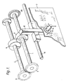
- Figure 1 is a schematic perspective and partly cut away view of the sheet feeding apparatus and sheet sensor;
- Figure 2 is a typical waveform obtained using apparatus of the kind shown in Figure 1;
- Figure 3 is a block diagram of the electronic apparatus for processing the output of the sensor in Figure 1;
- Figure 4 shows an oscillator circuit for use in the block diagram of Figure 3;
- Figure 5 illustrates graphically the variation in gain with core penetration for conventional solenoids;
- Figure 6 illustrates graphically the variation in gain with core penetration for a 10 mm diameter coil and for a flat coil; and,
- Figure 7 is a flow diagram illustrating operation of the apparatus.
- The sheet feeding apparatus shown in Figure 1 is for feeding banknotes and comprises two
parallel shafts shaft 1 is the sensor shaft and carries a rubber filledroller 5 and theshaft 2 is the datum shaft and carries asolid roller 6. Therollers gears rollers - Part of the surface of the
roller 5 engages anarm 12 which is mounted on apivot shaft 13 attached between the side plates. Aferrite core 14, cooperating with aflat coil 15, is mounted on the other end of thepivoted arm 12, i.e. remote from thepivot shaft 13. Thearm 12 is urged against theroller 5 under spring action. Theflat coil 15 is mounted on a printedcircuit board 3 on which the processing circuitry shown in Figures 3 and 4 is also mounted. In one example, theflat coil 15 has an inside diameter of about 12 mm and six turns, three on each side ofboard 3. Theferrite core 14 in this case has a diameter of about 6 mm and a length of about 30 mm. Its degree of penetration ie. the amount by which the core protrudes through the coil is 3 mm ± 1.5 mm. - When a note passes between the
rollers sensor roller 5 deflects causing pivotal movement of thearm 12. This causes relative movement between theferrite rod 14 and theflat coil 15 due to the angular movement of thearm 12 about thepivot shaft 13. The movement of theferrite core 14 through theflat coil 15 changes the inductance of the coil. - The passage of two superimposed notes between the
rollers - Figure 2 shows a
typical waveform 40 obtained from such a sensor. The small-amplitude variations x indicate, in analogue equivalent form, the variable frequency pattern produced by the sensor due to the eccentricity of the pinch rollers. Thus, the periodic pattern corresponds to the composite profile of the pinch rollers in one revolution. - It will be seen from Figure 2 that when a note passes between the pinch rollers the waveform pattern is offset by an amount y corresponding to the thickness of the note but the
offset pattern 41 suffers little distortion. - The coil 15 (shown diagrammatically in Figure 3) is connected to an
oscillator circuit 18 which varies in frequency with the penetration of the core through the coil. An eight-bit counter 19 receives the oscillator output and counts the number of pulses present in a predetermined period or time "window". Thus, the count during such a period represents the penetration of thecore 14 through thecoil 15 and the relative deflection of the rollers. The duration of the predetermined period or time "window" during which the count is made is predetermined by atimer 20 supplied with pulses by a crystal-controlledreference oscillator 21 - The count is fed to a
data latch circuit 22 and thence over adata bus 24 to amicroprocessor 23 responsible for monitoring the counts and detecting the presence of a sheet or sheets. As the data bus carries other data at other times, when the microprocessor requires data from the latch circuit it sends a suitable address signal over anaddress bus 26 to anaddress decode circuit 25 which signals the data latch circuit over aline 27. The microprocessor also supplies a data strobe signal overline 28 to thedata latch circuit 22. - The circuit shown in Figure 4 consists of an oscillator, the frequency of which depends upon the inductance of the
coil 15, capacitors 4 (typically each of 1500 pF) and a buffer, and is of conventional design. - In the example described, the oscillator operates at approximately 6 MHz and the duration of the sampling period or time "window" is such that the count obtained is greater than eight bits. However, the high-order data bits (those in excess of eight) are ignored and only the changes in the lower-order bits are used in the signal processing algorithm. This increases the resolution which can be obtained.
- The
pinch rollers timing disc 32 are driven by the main transport for the notes, producing thirty six timing pulses per revolution of the pinch rollers. These timing pulses define thirty six sampling points in each revolution of the rollers. At each timing pulse, the microprocessor supplies a "clear" signal overline 30 to clear the 8-bit counter and thetimer 20. Thetimer 20 then counts the pulses fromoscillator 21 and the counter 19 counts the pulses from theoscillator 18. When thetimer 20 overflows it stops thecounter 19 and sends a "data ready" signal overline 31 to the microprocessor. The microprocessor then addresses the data latch and acquires the data reading, as described above. - To generate and store the eccentricity profile of the rollers prior to the arrival of a note the microprocessor samples the signal from the sensor at each of the thirty six sampling instants and retains each sample value in a memory location. To smooth out the effects of random noise on the sampled values, a further reading is taken for each sample point and the value in the memory is replaced by the average of the existing value in the memory and the new sample value for that point.
- Operation of the apparatus is illustrated by the flow diagram in Figure 7. On the occurrence of each timing pulse, a data sample or count is read (step 50) and if the apparatus is in the profile generating mode described above, the sample is filtered (step 51) and stored (step 52) as described.
- If the apparatus is in its normal feed mode, the sample is filtered (step 53) and the corresponding eccentricity profile value is subtracted (step 54) to yield a difference value which is compared (step 55) with a first "note present" threshold set to about one half the value expected for a normal note thickness. In order to cope with noise variations, this
comparison step 55 will generally compare three succeeding difference values with the note present threshold. - If the difference values do not satisfy this test then this could be indicative of the fact that the trailing edge of a note has just passed or that the apparatus is in an idle state with no note passing. This is determined in a
step 56. If no note has just passed, then the difference value is compared with a TEST threshold (step 57). If the difference is greater than the TEST threshold this is indicative of the fact that the eccentricity profile value has been set too high and the apparatus will set an error flag (step 58) and cause the eccentricity profile to be relearned. In either event, a running thickness total is cleared (step 59) and operation returns to step 50. - During the passage of a note, successive difference values will be generated in
step 54 and these are added to a running thickness total (step 60). The final value of this thickness total will vary in accordance with the thickness of the note which has passed and with its length. In other words the total will vary with the product of the note thickness and the note length. The apparatus operates to continually update the thresholds which are used in the decision process and initially these thresholds will vary from start-up default values to final stabilised values. Thus, while a note is present, a decision is made (step 61) as to whether the thresholds are stable and if they are not then instead of making use of the running thickness total, the microprocessor compares an instantaneous thickness value ie. a single difference value fromstep 54 with a double thickness threshold (step 62). If the difference value exceeds this threshold then the note is rejected (step 63). However, if the thresholds are stable or the note does not exceed the threshold then operation returns to step 50. - As soon as it is determined in
step 55 that a note is not present and that in step 56 a trailing edge has just passed, a decision is again taken as to whether the thresholds are stable (step 64). Initially, the thresholds will not be stabilised and the running thickness total determined in step 60 is divided by the length of the note to generate an average thickness value which is then compared with a minimum thickness value instep 65. If the average thickness is less than the minimum threshold this could suggest a change in the type of note being fed or an incorrect threshold being used and in either case the note is rejected (step 56) and operation returns to step 50. If the average thickness exceeds the minimum threshold then all the thresholds used in the system are updated (step 67) using the latest acquired data and operation returns to step 50. In this case, a count of the number of notes passing is incremented. - Once the thresholds are stabilised, the microprocessor carries out a
step 68 afterstep 64 in which the running thickness total is compared with single and double threshold values. Typically, the single threshold value corresponds to 2/3 times the expected integrated thickness total for a single note and the double note threshold corresponds to 1.4 times the integrated thickness total expected for a single note. If the actual thickness total falls between these two thresholds then operation passes to step 65 which operates as before. Otherwise, the note is rejected (step 66). - Figure 5 illustrates the results of tests carried out in which the
flat coil 15 is replaced with a solenoid as in our earlier European Patent Application No.85309261.7. In Figure 5,curve 43 corresponds to a 10mm diameter coil,curve 44 to a 12mm diameter coil,curve 45 to a 14mm diameter coil andcurve 46 to a 16mm diameter coil. As can be seen in Figure 5, increasing the diameter of the coil increases linearity but significantly decreases the gain of the system. Linearity, or "operating range" is defined as the penetration range for which the gain does not vary by more than 10% of the nominal value. If a 14 mm diameter solenoid is chosen so as to be sufficient to give the required mechanical clearances, thecapacitors 4 are reduced to 150 pF to compensate for the gain loss but the resulting system is found to be too insensitive. Making thecapacitors 4 any smaller results in a high susceptibility to external stray capacitances. - We have found that replacing the known solenoid with a flat coil significantly increases the gain without substantially affecting linearity. This is apparent from Figure 6 which compares the variation of gain with ferrite core penetration for a solenoid with a 10 mm internal diameter (curve 47) and a flat coil with a 12 mm internal diameter (curve 48). The
broken line 49 in Figure 6 represents 10% gain drop-off. As can be seen, for penetration distances in the order 1.5-4.0 mm there is little change in gain for the flat coil although there is a significant change in gain for the solenoid. - The flat coil offers the benefits of ease of manufacture and a higher reliability than the conventional solenoid.
Claims (7)
- Apparatus for sensing the passage of sheets through a nip, comprising:
a pair of guide members (5, 6) whose surfaces define the nip, the guide members (5, 6) being movable in a cyclic manner to advance the sheets through the nip;
sensing means for sensing the deflection of one guide member relative to the other, the sensing means including a signal generator (18) providing a train of signals the frequency of which varies with the amount of relative deflection of the guide members, and a counter (19) arranged to count the signals from the signal generator (18) in an interval of predetermined length;
and detecting means (23) responsive to the output of the sensing means to establish the presence or absence of a sheet between the guide members (5, 6), the detecting means (23) being responsive to a count from the sensing means to establish the presence or absence of a sheet between the guide members (5, 6);
wherein the sensing means includes a coil (15) and a core (14) so mounted that relative displacement of the guide members (5, 6) by the passage of a sheet causes relative movement of the core (14) and coil (15), and in that the coil (15) is connected to the signal generator (18) and controls the frequency of the signal generator (18) in accordance with the degree of penetration of the core (14) through the coil (15),
characterised in that said coil (15) is substantially flat. - Apparatus for sensing the passage of sheets through a nip, comprising:
a pair of guide members (5, 6) whose surfaces define the nip, the guide members (5, 6) being movable in a cyclic manner to advance the sheets through the nip;
sensing means for sensing the deflection of one guide member (5) relative to the other (6), the sensing means including a signal generator (18) providing a train of signals the frequency of which varies with the amount of relative deflection of the guide members (5, 6), and a counter (19) arranged to count the signals from the signal generator (18) in an interval of predetermined length;
monitoring means (23) for monitoring the output of the sensing means and for storing counts representing relative deflections of the guide members (5, 6) in a cycle of movement of the guide members (5, 6) when no sheet is present;
and detecting means (23) responsive to the output of the sensing means to establish the presence or absence of a sheet between the guide members, the detecting means (23) being responsive to a subsequent count from the sensing means and to the stored counts for comparing, with a predetermined threshold, the difference between the subsequent count and a stored count for a corresponding position in the cycle of movement of the guide members, to establish the presence or absence of a sheet between the guide members;
wherein the sensing means includes a coil (15) and a core (14) so mounted that relative displacement of the guide members (5, 6) by the passage of a sheet causes relative movement of the core (14) and coil (15), and in that the coil (15) is connected to the signal generator (18) and controls the frequency of the signal generator (18) in accordance with the degree of penetration of the core (14) through the coil (15), characterised in that said coil (15) is substantially flat. - Apparatus in accordance with claim 2 in which the detecting means (23) includes means defining a second and higher threshold, a difference which lies between the two thresholds indicating the presence of one sheet and a difference which exceeds the second and higher threshold indicating the presence of two or more sheets between the guide members (5, 6).
- Apparatus in accordance with claim 2, in which the guide members (5, 6) are rollers.
- Apparatus in accordance with claim 4 in which one of the rollers (6) is mounted on a fixed shaft (2) and the other (5) is mounted to permit its displacement relative to the shaft (2) of the first roller.
- Apparatus according to any of the preceding claims, further including a printed circuit board (3) which carries the flat coil (15) and other components of the detecting means.
- Apparatus according to claim 6, wherein the sensing means comprises a pair of axially aligned flat coils which, where a printed circuit board (3) is provided, are mounted on opposite sides of the board.
Priority Applications (1)
| Application Number | Priority Date | Filing Date | Title |
|---|---|---|---|
| AT89305270T ATE79826T1 (en) | 1988-05-31 | 1989-05-24 | LEAF SENSOR. |
Applications Claiming Priority (2)
| Application Number | Priority Date | Filing Date | Title |
|---|---|---|---|
| GB888812893A GB8812893D0 (en) | 1988-05-31 | 1988-05-31 | Apparatus for sensing sheets |
| GB8812893 | 1988-05-31 |
Publications (2)
| Publication Number | Publication Date |
|---|---|
| EP0344967A1 EP0344967A1 (en) | 1989-12-06 |
| EP0344967B1 true EP0344967B1 (en) | 1992-08-26 |
Family
ID=10637845
Family Applications (1)
| Application Number | Title | Priority Date | Filing Date |
|---|---|---|---|
| EP89305270A Expired - Lifetime EP0344967B1 (en) | 1988-05-31 | 1989-05-24 | Apparatus for sensing sheets |
Country Status (5)
| Country | Link |
|---|---|
| US (1) | US5007628A (en) |
| EP (1) | EP0344967B1 (en) |
| AT (1) | ATE79826T1 (en) |
| DE (1) | DE68902582T2 (en) |
| GB (1) | GB8812893D0 (en) |
Families Citing this family (14)
| Publication number | Priority date | Publication date | Assignee | Title |
|---|---|---|---|---|
| US5097273A (en) * | 1989-09-04 | 1992-03-17 | Minolta Camera Kabushiki Kaisha | Recording medium detecting apparatus |
| US5203555A (en) * | 1992-09-04 | 1993-04-20 | Pitney Bowes Inc. | Adjustable dampening device in an apparatus for detecting double fed sheets |
| US5437445A (en) * | 1992-10-08 | 1995-08-01 | Pitney Bowes Inc. | Method and apparatus for detecting double fed sheets |
| US5446355A (en) * | 1993-09-28 | 1995-08-29 | Eastman Kodak Company | Media transport system with high precision position and speed control |
| GB9525767D0 (en) * | 1995-12-16 | 1996-02-14 | At & T Global Inf Solution | Apparatus for detecting multiple superposed sheets |
| US5833229A (en) * | 1996-07-29 | 1998-11-10 | Prim Hall Enterprises, Inc. | Bindery feeder and method of operation |
| US6089561A (en) * | 1998-06-08 | 2000-07-18 | Ncr Corporation | Document feeder |
| DE10345064A1 (en) * | 2003-09-26 | 2005-04-14 | Giesecke & Devrient Gmbh | Sheet material thickness measurement device, especially for measuring banknote thickness, has two rigidly mounted rollers, through which material passes, with one of rollers elastically deformed by material |
| DE102004030618A1 (en) * | 2004-06-24 | 2006-01-26 | Giesecke & Devrient Gmbh | Measuring device for measuring the thickness of sheet material like bank-notes has a multitrack thickness sensor with two opposing fixed shafts driven synchronously |
| DE102004045170A1 (en) * | 2004-09-17 | 2006-03-23 | Giesecke & Devrient Gmbh | Banknote thickness measuring method for banknote processing machine, involves summing forces measured at axle ends of one elastic roller, and determining thickness of banknotes and/or variation in thickness of banknotes from summed forces |
| US20070108025A1 (en) * | 2005-11-17 | 2007-05-17 | Jean-Marc Boudreau | Slides for endless belt conveyors |
| DE102009004688A1 (en) * | 2009-01-12 | 2010-07-22 | Beb Industrie-Elektronik Ag | Apparatus for detecting a thickness or thickness variation of a flat article |
| DE102009005171B4 (en) | 2009-01-15 | 2025-05-08 | Beb Industrie-Elektronik Ag | Device and method for detecting reflected and/or emitted light from an object |
| US10766727B2 (en) | 2015-11-18 | 2020-09-08 | Glory Ltd. | Paper sheet processing device and paper sheet processing method |
Family Cites Families (9)
| Publication number | Priority date | Publication date | Assignee | Title |
|---|---|---|---|---|
| AT334118B (en) * | 1975-07-15 | 1976-12-27 | Gao Ges Automation Org | MEASURING DEVICE FOR MEASURING THICKNESS DIFFERENCES IN RECORDING MEDIA, SUCH AS BANKNOTES ETC. |
| DE2930270C2 (en) * | 1979-07-26 | 1986-04-24 | M.A.N.- Roland Druckmaschinen AG, 6050 Offenbach | Control device for the feeding of sheets |
| WO1982001698A1 (en) | 1980-11-07 | 1982-05-27 | Tee Victor G | Apparatus for detecting the thickness of sheets |
| EP0063159B1 (en) * | 1980-12-08 | 1985-10-30 | De La Rue Systems Limited | Improvements in sheet handling machines |
| DE3201407A1 (en) * | 1981-03-19 | 1982-10-07 | VEB Kombinat Polygraph "Werner Lamberz" Leipzig, DDR 7050 Leipzig | MONITORING DEVICE FOR MONITORING BOOK BLOCK FOR MATCHING MACHINES |
| US4462587A (en) * | 1981-09-25 | 1984-07-31 | Diebold Incorporated | Method of and system for detecting bill status in a paper money dispenser |
| DE3235235A1 (en) * | 1981-09-25 | 1983-04-14 | Diebold, Inc., 44702 Canton, Ohio | Method for determining the status or the type of banknotes in a cash dispenser and device for implementing the method |
| CH660350A5 (en) * | 1983-06-14 | 1987-04-15 | Ferag Ag | DEVICE FOR DETERMINING MULTIPLE-USED PLACES IN A CONTINUOUSLY REQUIRED FLOW OF UNIFORM DISTANCES FROM PRINTING PRODUCTS AND THE USE OF THIS DEVICE. |
| GB8432438D0 (en) * | 1984-12-21 | 1985-02-06 | De La Rue Syst | Sensing sheets |
-
1988
- 1988-05-31 GB GB888812893A patent/GB8812893D0/en active Pending
-
1989
- 1989-05-24 DE DE8989305270T patent/DE68902582T2/en not_active Expired - Lifetime
- 1989-05-24 EP EP89305270A patent/EP0344967B1/en not_active Expired - Lifetime
- 1989-05-24 AT AT89305270T patent/ATE79826T1/en not_active IP Right Cessation
- 1989-05-26 US US07/358,202 patent/US5007628A/en not_active Expired - Fee Related
Also Published As
| Publication number | Publication date |
|---|---|
| US5007628A (en) | 1991-04-16 |
| GB8812893D0 (en) | 1988-07-06 |
| ATE79826T1 (en) | 1992-09-15 |
| EP0344967A1 (en) | 1989-12-06 |
| DE68902582T2 (en) | 1993-03-18 |
| DE68902582D1 (en) | 1992-10-01 |
Similar Documents
| Publication | Publication Date | Title |
|---|---|---|
| EP0186442B1 (en) | Method and apparatus for sensing sheets | |
| US5007628A (en) | Apparatus for sensing sheets | |
| US4849915A (en) | Monitoring sheet length | |
| EP0496754B1 (en) | Method and apparatus for validating money | |
| US5448079A (en) | Reflective pattern with coded beginning and end formed on the surface of a sheet handling cylinder for detecting the presence and position of the sheet | |
| EP0344938B1 (en) | Apparatus for detecting the passage of multiple superposed sheets along a feed path | |
| USRE35084E (en) | Method for measuring a length and electronic slide caliper | |
| US4982947A (en) | Apparatus for detecting the passage of multiple superposed sheets along a feed path | |
| JPS59198303A (en) | Sensor for position of conductive element | |
| US5853089A (en) | Apparatus for detecting multiple superposed sheets | |
| US20170190529A1 (en) | Apparatus and Method for Controlling a Banknote Feed Rate | |
| JPH01501657A (en) | coin detection device | |
| US5353905A (en) | Coin sorting device | |
| JPH0749950B2 (en) | Thickness detection device for paper sheets | |
| US4317989A (en) | Apparatus and method for measurement of board length | |
| JPS5897603A (en) | Thickness detector for paper sheet or the like | |
| JPH0353122Y2 (en) | ||
| US20060061370A1 (en) | Method for measuring thickness of print products passing spaced apart at specific distances in a conveying flow through a measuring device | |
| DE102004053891A1 (en) | Method for capacitive identification of error sheets in printing press entails moving of printed sheets through precision capacitor from which continuous or analogue measurement signal-data stream is made available | |
| JPS6128185A (en) | Banknote identification device | |
| JP2651468B2 (en) | Duplicate sheet detection device | |
| JPS6260344B2 (en) | ||
| JPH0228446A (en) | Multiple sheet passage detector | |
| JPH0319994B2 (en) | ||
| JPS59121596A (en) | Discrimination of sheet paper |
Legal Events
| Date | Code | Title | Description |
|---|---|---|---|
| PUAI | Public reference made under article 153(3) epc to a published international application that has entered the european phase |
Free format text: ORIGINAL CODE: 0009012 |
|
| AK | Designated contracting states |
Kind code of ref document: A1 Designated state(s): AT BE CH DE ES FR GB IT LI NL SE |
|
| 17P | Request for examination filed |
Effective date: 19900315 |
|
| 17Q | First examination report despatched |
Effective date: 19911129 |
|
| GRAA | (expected) grant |
Free format text: ORIGINAL CODE: 0009210 |
|
| AK | Designated contracting states |
Kind code of ref document: B1 Designated state(s): AT BE CH DE ES FR GB IT LI NL SE |
|
| PG25 | Lapsed in a contracting state [announced via postgrant information from national office to epo] |
Ref country code: NL Effective date: 19920826 Ref country code: BE Effective date: 19920826 Ref country code: IT Free format text: LAPSE BECAUSE OF FAILURE TO SUBMIT A TRANSLATION OF THE DESCRIPTION OR TO PAY THE FEE WITHIN THE PRE;WARNING: LAPSES OF ITALIAN PATENTS WITH EFFECTIVE DATE BEFORE 2007 MAY HAVE OCCURRED AT ANY TIME BEFORE 2007. THE CORRECT EFFECTIVE DATE MAY BE DIFFERENT FROM THE ONE RECORDED.SCRIBED TIME-LIMIT Effective date: 19920826 Ref country code: ES Free format text: THE PATENT HAS BEEN ANNULLED BY A DECISION OF A NATIONAL AUTHORITY Effective date: 19920826 Ref country code: AT Effective date: 19920826 Ref country code: CH Effective date: 19920826 Ref country code: LI Effective date: 19920826 Ref country code: SE Free format text: THE PATENT HAS BEEN ANNULLED BY A DECISION OF A NATIONAL AUTHORITY Effective date: 19920826 |
|
| REF | Corresponds to: |
Ref document number: 79826 Country of ref document: AT Date of ref document: 19920915 Kind code of ref document: T |
|
| REF | Corresponds to: |
Ref document number: 68902582 Country of ref document: DE Date of ref document: 19921001 |
|
| REG | Reference to a national code |
Ref country code: CH Ref legal event code: PL |
|
| ET | Fr: translation filed | ||
| NLV1 | Nl: lapsed or annulled due to failure to fulfill the requirements of art. 29p and 29m of the patents act | ||
| PLBE | No opposition filed within time limit |
Free format text: ORIGINAL CODE: 0009261 |
|
| STAA | Information on the status of an ep patent application or granted ep patent |
Free format text: STATUS: NO OPPOSITION FILED WITHIN TIME LIMIT |
|
| 26N | No opposition filed | ||
| REG | Reference to a national code |
Ref country code: GB Ref legal event code: 732E |
|
| REG | Reference to a national code |
Ref country code: FR Ref legal event code: TP Ref country code: FR Ref legal event code: CA |
|
| REG | Reference to a national code |
Ref country code: GB Ref legal event code: IF02 |
|
| PGFP | Annual fee paid to national office [announced via postgrant information from national office to epo] |
Ref country code: DE Payment date: 20080529 Year of fee payment: 20 |
|
| PGFP | Annual fee paid to national office [announced via postgrant information from national office to epo] |
Ref country code: GB Payment date: 20080528 Year of fee payment: 20 |
|
| REG | Reference to a national code |
Ref country code: GB Ref legal event code: 732E Free format text: REGISTERED BETWEEN 20090122 AND 20090128 |
|
| REG | Reference to a national code |
Ref country code: GB Ref legal event code: PE20 Expiry date: 20090523 |
|
| REG | Reference to a national code |
Ref country code: FR Ref legal event code: TP |
|
| PG25 | Lapsed in a contracting state [announced via postgrant information from national office to epo] |
Ref country code: GB Free format text: LAPSE BECAUSE OF EXPIRATION OF PROTECTION Effective date: 20090523 |
|
| PGFP | Annual fee paid to national office [announced via postgrant information from national office to epo] |
Ref country code: FR Payment date: 20080514 Year of fee payment: 20 |