EP0344066A1 - Tool for stripping coaxial cables - Google Patents
Tool for stripping coaxial cables Download PDFInfo
- Publication number
- EP0344066A1 EP0344066A1 EP89401415A EP89401415A EP0344066A1 EP 0344066 A1 EP0344066 A1 EP 0344066A1 EP 89401415 A EP89401415 A EP 89401415A EP 89401415 A EP89401415 A EP 89401415A EP 0344066 A1 EP0344066 A1 EP 0344066A1
- Authority
- EP
- European Patent Office
- Prior art keywords
- conductor
- stripped
- dielectric
- sleeve
- coaxial cable
- Prior art date
- Legal status (The legal status is an assumption and is not a legal conclusion. Google has not performed a legal analysis and makes no representation as to the accuracy of the status listed.)
- Withdrawn
Links
Images
Classifications
-
- H—ELECTRICITY
- H02—GENERATION; CONVERSION OR DISTRIBUTION OF ELECTRIC POWER
- H02G—INSTALLATION OF ELECTRIC CABLES OR LINES, OR OF COMBINED OPTICAL AND ELECTRIC CABLES OR LINES
- H02G1/00—Methods or apparatus specially adapted for installing, maintaining, repairing or dismantling electric cables or lines
- H02G1/12—Methods or apparatus specially adapted for installing, maintaining, repairing or dismantling electric cables or lines for removing insulation or armouring from cables, e.g. from the end thereof
- H02G1/1202—Methods or apparatus specially adapted for installing, maintaining, repairing or dismantling electric cables or lines for removing insulation or armouring from cables, e.g. from the end thereof by cutting and withdrawing insulation
- H02G1/1204—Hand-held tools
- H02G1/1221—Hand-held tools the cutting element rotating about the wire or cable
- H02G1/1226—Hand-held tools the cutting element rotating about the wire or cable making a helical cut
Definitions
- the present invention relates to a tool for stripping coaxial cables comprising an outer conductor covered with an insulating sheath and an axial conductor separated from the outer conductor by a dielectric material.
- the present invention proposes to remedy this gap and, to do this, it relates to a stripping tool which is characterized in that it comprises a sleeve provided with an internal channel whose cross section is slightly greater than that of the coaxial cable to be stripped, and a knife holder projecting into the sleeve with which it delimits a guide cavity intended to receive one of the end parts of the coaxial cable to be stripped, the knife holder comprising a front knife and a rear knife axially offset and positioned in the guide cavity so that the first can remove the dielectric and the second, the outer conductor and the sheath of the coaxial cable to be stripped when the latter is rotated about its axis, as well as a calibrated orifice intended to receive with little play the part of the axial conductor which is free of the dielectric.
- the sleeve advantageously has a slot in its part located behind said knives.
- the knife holder has a notch, the bottom of which intersects the calibrated orifice, parallel to the longitudinal axis of the latter.
- the part of the axial conductor which is stripped of the dielectric abuts against the bottom of the calibrated orifice when the stripping is finished, which makes it possible to give it a constant length.
- the calibrated orifice is extended axially by a hole whose cross section is smaller than its own. Thanks to this hole, the saw burrs present at the free end of the axial conductor can in fact be eliminated by friction against the entry of the hole when, at the end of stripping, the tool continues to be driven in rotation around its axis.
- the tool according to the invention has been developed for stripping one of the end parts of a coaxial cable such as that designated by the reference 1 in Figures 4 to 6 and which comprises in a manner known per se an outer conductor 2 covered with an insulating sheath 3 and an axial conductor 4 separated from the outer conductor 2 by a dielectric material 5.
- the outer conductor 2 of the coaxial cable can be constituted by a straight or corrugated tube or by a strip laminated to the insulating sheath 3.
- This tool comprises a cylindrical sleeve 6 provided with an internal channel 7 whose cross section is slightly greater than that of the coaxial cable 1, and a knife holder 8 projecting into the sleeve 6 with which it delimits a guide cavity 9 intended to receive the terminal part of the coaxial cable which must be stripped.
- the knife holder 8 comprises an anterior knife 10 and a posterior knife 11 axially offset and positioned in the guide cavity 9 so that the first can remove the dielectric 5 and the second the outer conductor 2 and the sheath 3 of the cable coaxial to be stripped when the tool is rotated about its longitudinal axis. It further comprises a calibrated orifice 12 intended to receive with a small clearance the end part of the axial conductor 4 which must be rid of the dielectric 5, a hole 13 axially extending the calibrated orifice 12 and whose section is smaller than that of this last, as well as a notch 14 whose bottom intersects the calibrated orifice 12 and the hole 13, parallel to their longitudinal axis.
- the sleeve 8 As for the sleeve 8, it comprises in its part located behind the knives 10, 11 an oblique slot 15 intended to allow the evacuation of the chips formed during stripping.
- transverse sides of the oblique slot 15 are coplanar with the bottom of the notch 14 which is delimited towards the rear by a wall 16 extending in the plane of the rear longitudinal side 15a of the oblique slot 15.
- the knife holder 8 is provided with an axial extension 17 inserted in a blind hole formed in one of the ends of a cylindrical handle 18 knurled on its lateral surface. As clearly shown in FIGS. 1 and 2, the sleeve 6 bears against the handle 18, while the knife holder 8 is fixed to the sleeve 6 and to the handle 18 by two countersunk screws 19.
- the procedure is as follows.
- the terminal end to be stripped of the coaxial cable 1 is introduced into the guide cavity 9 of the sleeve, until it comes into abutment against the front knife 10.
- the tool is then rotated around its longitudinal axis, by gripping it by its gripping handle 18.
- the prior tool 10 then cuts the dielectric 5 of the coaxial cable into shavings, while the central conductor 4 of the latter gradually penetrates in the calibrated orifice 12.
- front tool 10 works alone until the dielectric 5 is removed over a length A equal to the axial distance separating the front tools 10 and rear tools 11.
- the rear tool 11 in turn becomes active and cuts the external conductor 2 and the sheath 3 of the coaxial cable into chips, its action and that of the anterior knife 10 continuing until the axial conductor 4 of the coaxial cable comes into abutment against the bottom of the calibrated orifice 12 of the knife holder 8, that is to say until the front knife 10 removes the dielectric 5 over a length B equal to the axial distance separating said knife front 10 of the bottom of the calibrated orifice 12.
- the tool which has just been described can be used by hand. It could however be adapted on an electric or pneumatic screwdriver. To do this, it would suffice to make in the axis of the free end of the axial extension 17 of the knife holder 8 a threaded hole with the pitch of commercial chucks, to remove the handle 18, and to screw the axial extension 17 of the knife holder 8 to the place of the screwdriver chuck.
Abstract
Description
La présente invention concerne un outil pour le dénudage de câbles coaxiaux comprenant un conducteur extérieur recouvert d'une gaine isolante et un conducteur axial séparé du conducteur extérieur par un matériau diélectrique.The present invention relates to a tool for stripping coaxial cables comprising an outer conductor covered with an insulating sheath and an axial conductor separated from the outer conductor by a dielectric material.
Il n'existe pas actuellement d'outils permettant de dénuder avec rapidité et précision les parties terminales des câbles coaxiaux utilisés dans les réseaux de télécommunication.Currently, there are no tools for quickly and accurately stripping the end portions of coaxial cables used in telecommunications networks.
La présente invention se propose de remédier à cette lacune et, pour ce faire, elle a pour objet un outil de dénudage qui se caractérise en ce qu'il comprend un manchon pourvu d'un canal interne dont la section est légèrement supérieure à celle du câble coaxial à dénuder, et un porte-couteaux faisant saillie dans le manchon avec lequel il délimite une cavité de guidage destinée à recevoir l'une des parties terminales du câble coaxial à dénuder, le porte-couteaux comportant un couteau antérieur et un couteau postérieur décalés axialement et positionnés dans la cavité de guidage de telle sorte que le premier puisse enlever le diélectrique et le second, le conducteur extérieur et la gaine du câble coaxial à dénuder lorsque celui-ci est entraîné en rotation autour de son axe, ainsi qu'un orifice calibré destiné à recevoir avec un faible jeu la partie du conducteur axial qui est débarrassée du diélectrique.The present invention proposes to remedy this gap and, to do this, it relates to a stripping tool which is characterized in that it comprises a sleeve provided with an internal channel whose cross section is slightly greater than that of the coaxial cable to be stripped, and a knife holder projecting into the sleeve with which it delimits a guide cavity intended to receive one of the end parts of the coaxial cable to be stripped, the knife holder comprising a front knife and a rear knife axially offset and positioned in the guide cavity so that the first can remove the dielectric and the second, the outer conductor and the sheath of the coaxial cable to be stripped when the latter is rotated about its axis, as well as a calibrated orifice intended to receive with little play the part of the axial conductor which is free of the dielectric.
Grâce à cet outil, le dénudage des parties terminales des câbles coaxiaux peut maintenant être réalisé rapidement et avec une grande précision. Il suffit en effet d'introduire la partie terminale à dénuder dans la cavité de guidage et de faire tourner l'outil autour de son axe longitudinal pour que les couteaux antérieur et postérieur enlèvent le diélectrique, le conducteur extérieur et la gaine sur les longueurs souhaitées.Thanks to this tool, the stripping of the end parts of coaxial cables can now be carried out quickly and with great precision. It suffices to introduce the end part to be stripped into the guide cavity and to rotate the tool around its longitudinal axis so that the front and rear knives remove the dielectric, the external conductor and the sheath over the desired lengths.
Pour faciliter l'évacuation des copeaux formés par les couteaux antérieur et postérieur, le manchon comporte avantageusement une fente dans sa partie située en arrière desdits couteaux.To facilitate the evacuation of the chips formed by the front and rear knives, the sleeve advantageously has a slot in its part located behind said knives.
Par ailleurs, le porte-couteaux comporte une entaille dont le fond coupe l'orifice calibré, parallèlement à l'axe longitudinal de ce dernier.Furthermore, the knife holder has a notch, the bottom of which intersects the calibrated orifice, parallel to the longitudinal axis of the latter.
Les risques pour que des copeaux s'accumulent dans l'orifice calibré et perturbent le fonctionnement de l'outil sont ainsi éliminés.This eliminates the risk of chips accumulating in the calibrated hole and disturbing the operation of the tool.
Avantageusement, la partie du conducteur axial qui est débarrasée du diélectrique vient en butée contre le fond de l'orifice calibré lorsque le dénudage est terminé, ce qui permet de lui donner une longueur constante.Advantageously, the part of the axial conductor which is stripped of the dielectric abuts against the bottom of the calibrated orifice when the stripping is finished, which makes it possible to give it a constant length.
Il est par ailleurs souhaitable que l'orifice calibré soit prolongé axialement par un trou dont la section est inférieure à la sienne. Grâce à ce trou, les bavures de sciage présentes à l'extrémité libre du conducteur axial peuvent en effet être éliminées par frottement contre l'entrée du trou lorsqu' à la fin du dénudage, l'outil continue à être entraîné en rotation autour de son axe.It is moreover desirable that the calibrated orifice is extended axially by a hole whose cross section is smaller than its own. Thanks to this hole, the saw burrs present at the free end of the axial conductor can in fact be eliminated by friction against the entry of the hole when, at the end of stripping, the tool continues to be driven in rotation around its axis.
Un mode d'exécution de la présente invention sera décrit ci-après à titre d'exemple nullement limitatif en référence au dessin annexé dans lequel :
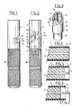
- La figure 1 est une vue de côté de l'outil de dénudage conforme à l'invention ;
- La figure 2 en est une vue de face ;
- La figure 3 est une vue en perspective de son porte-couteaux ; et
- Les figures 4 à 6 sont des vues schématiques en coupe d'un câble coaxial susceptible d'être dénudé à l'aide de l'outil conforme à l'invention, ces figures montrant le câble coaxial respectivement avant, pendant et après le dénudage.
- Figure 1 is a side view of the stripping tool according to the invention;
- Figure 2 is a front view;
- Figure 3 is a perspective view of its knife holder; and
- Figures 4 to 6 are schematic sectional views of a coaxial cable capable of being stripped using the tool according to the invention, these figures showing the coaxial cable respectively before, during and after stripping.
L'outil conforme à l'invention a été mis au point pour dénuder l'une des parties terminales d'un câble coaxial tel que celui désigné par la référence 1 sur les figures 4 à 6 et qui comprend d'une manière connue en soi un conducteur extérieur 2 recouvert d'une gaine isolante 3 et un conducteur axial 4 séparé du conducteur extérieur 2 par un matériau diélectrique 5.The tool according to the invention has been developed for stripping one of the end parts of a coaxial cable such as that designated by the reference 1 in Figures 4 to 6 and which comprises in a manner known per se an
On précisera à toutes fins utiles que le conducteur extérieur 2 du câble coaxial peut être constitué par un tube droit ou annelé ou par un feuillard contre-collé à la gaine isolante 3.It will be specified for all practical purposes that the
Cet outil comprend un manchon cylindrique 6 pourvu d'un canal interne 7 dont la section est légèrement supérieure à celle du câble coaxial 1, et un porte-couteaux 8 faisant saillie dans le manchon 6 avec lequel il délimite une cavité de guidage 9 destinée à recevoir la partie terminale du câble coaxial qui doit être dénudée.This tool comprises a
Le porte-couteaux 8 comporte un couteau antérieur 10 et un couteau postérieur 11 décalés axialement et positionnés dans la cavité de guidage 9 de telle sorte que le premier puisse enlever le diélectrique 5 et le second le conducteur extérieur 2 et la gaine 3 du câble coaxial à dénuder lorsque l'outil est entraîné en rotation autour de son axe longitudinal. Il comporte en outre un orifice calibré 12 destiné à recevoir avec un faible jeu la partie terminale du conducteur axial 4 qui doit être débarrassée du diélectrique 5, un trou 13 prolongeant axialement l'orifice calibré 12 et dont la section est inférieure à celle de ce dernier, ainsi qu'une entaille 14 dont le fond coupe l'orifice calibré 12 et le trou 13, parallèlement à leur axe longitudinal.The
Quant au manchon 8, il comporte dans sa partie située en arrière des couteaux 10, 11 une fente oblique 15 destinée à permettre l'évacuation des copeaux formés pendant le dénudage.As for the
On précisera ici que les côtés transversaux de la fente oblique 15 sont coplanaires avec le fond de l'entaille 14 qui est délimitée vers l'arrière par une paroi 16 s'étendant dans le plan du côté longitudinal postérieur 15a de la fente oblique 15.It will be specified here that the transverse sides of the
On précisera également que le porte-couteaux 8 est pourvu d'un prolongement axial 17 inséré dans un trou borgne ménagé dans l'une des extrémités d'un manche cylindrique 18 moleté sur sa surface latérale. Comme le montrent clairement les figures 1 et 2, le manchon 6 s'appuie contre le manche 18, tandis que le porte-couteaux 8 est fixé au manchon 6 et au manche 18 par deux vis noyées 19.It will also be noted that the
Pour utiliser l'outil de dénudage selon la présente invention, on procède de la manière suivante.To use the stripping tool according to the present invention, the procedure is as follows.
On introduit tout d'abord l'extrémité terminale à dénuder du câble coaxial 1 dans la cavité de guidage 9 du manchon, jusqu'à ce qu'elle vienne en butée contre le couteau antérieur 10.First of all, the terminal end to be stripped of the coaxial cable 1 is introduced into the
On fait ensuite tourner l'outil autour de son axe longitudinal, en le saisissant par son manche de préhension 18. L'outil antérieur 10 découpe alors en copeaux le diélectrique 5 du câble coaxial, tandis que le conducteur central 4 de ce dernier pénètre progressivement dans l'orifice calibré 12.The tool is then rotated around its longitudinal axis, by gripping it by its
On notera ici que l'outil antérieur 10 travaille seul jusqu'à ce que le diélectrique 5 soit enlevé sur une longueur A égale à la distance axiale séparant les outils antérieur 10 et postérieur 11.It will be noted here that the
Puis, l'outil postérieur 11 devient à son tour actif et découpe en copeaux le conducteur extérieur 2 et la gaine 3 du câble coaxial, son action et celle du couteau antérieur 10 se poursuivant jusqu'à ce que le conducteur axial 4 du câble coaxial vienne en butée contre le fond de l'orifice calibré 12 du porte-couteaux 8, c'est-à-dire jusqu'à ce que le couteau antérieur 10 enlève le diélectrique 5 sur une longueur B égale à la distance axiale séparant ledit couteau antérieur 10 du fond de l'orifice calibré 12.Then, the
Il est souhaitable de faire tourner l'outil pendant plusieurs tours après la venue en butée du conducteur axial 4 contre le fond de l'orifice calibré 12. Cette procédure permet en effet de donner à la partie terminale dénudée du câble coxial un aspect esthétique pleinement satisfaisant. Elle permet en outre d'éliminer les bavures de sciage qui seraient présentes à l'extrémité du conducteur axial, ces bavures étant éliminées en entrant en contact avec l'entrée du trou 13.It is desirable to rotate the tool for several turns after the
L'outil qui vient d'être décrit est utilisable à la main. Il pourrait toutefois être adapté sur une visseuse électrique ou pneumatique. Pour ce faire, il suffirait de réaliser dans l'axe de l'extrémité libre du prolongement axial 17 du porte-couteaux 8 un trou taraudé au pas des mandrins du commerce, de retirer le manche 18, et de visser le prolongement axial 17 du porte-couteaux 8 à la place du mandrin de la visseuse.The tool which has just been described can be used by hand. It could however be adapted on an electric or pneumatic screwdriver. To do this, it would suffice to make in the axis of the free end of the
Claims (6)
Applications Claiming Priority (2)
| Application Number | Priority Date | Filing Date | Title |
|---|---|---|---|
| FR8806995 | 1988-05-26 | ||
| FR8806995A FR2632128B1 (en) | 1988-05-26 | 1988-05-26 | TOOL FOR STRIPPING COAXIAL CABLES |
Publications (1)
| Publication Number | Publication Date |
|---|---|
| EP0344066A1 true EP0344066A1 (en) | 1989-11-29 |
Family
ID=9366632
Family Applications (1)
| Application Number | Title | Priority Date | Filing Date |
|---|---|---|---|
| EP89401415A Withdrawn EP0344066A1 (en) | 1988-05-26 | 1989-05-24 | Tool for stripping coaxial cables |
Country Status (2)
| Country | Link |
|---|---|
| EP (1) | EP0344066A1 (en) |
| FR (1) | FR2632128B1 (en) |
Cited By (2)
| Publication number | Priority date | Publication date | Assignee | Title |
|---|---|---|---|---|
| FR2702849A1 (en) * | 1993-03-15 | 1994-09-23 | Alroc Roux Robert Fils Sa | Device for stripping a rod |
| WO2010031021A2 (en) * | 2008-09-15 | 2010-03-18 | Commscope, Inc. Of North Carolina | Coaxial cable end preparation tool and related methods |
Citations (2)
| Publication number | Priority date | Publication date | Assignee | Title |
|---|---|---|---|---|
| US3659483A (en) * | 1970-01-15 | 1972-05-02 | James J Matthews | Jacket stripping tool |
| EP0101191A2 (en) * | 1982-08-17 | 1984-02-22 | AMP INCORPORATED (a New Jersey corporation) | Tool and method for trimming coaxial cable |
-
1988
- 1988-05-26 FR FR8806995A patent/FR2632128B1/en not_active Expired - Lifetime
-
1989
- 1989-05-24 EP EP89401415A patent/EP0344066A1/en not_active Withdrawn
Patent Citations (2)
| Publication number | Priority date | Publication date | Assignee | Title |
|---|---|---|---|---|
| US3659483A (en) * | 1970-01-15 | 1972-05-02 | James J Matthews | Jacket stripping tool |
| EP0101191A2 (en) * | 1982-08-17 | 1984-02-22 | AMP INCORPORATED (a New Jersey corporation) | Tool and method for trimming coaxial cable |
Cited By (3)
| Publication number | Priority date | Publication date | Assignee | Title |
|---|---|---|---|---|
| FR2702849A1 (en) * | 1993-03-15 | 1994-09-23 | Alroc Roux Robert Fils Sa | Device for stripping a rod |
| WO2010031021A2 (en) * | 2008-09-15 | 2010-03-18 | Commscope, Inc. Of North Carolina | Coaxial cable end preparation tool and related methods |
| WO2010031021A3 (en) * | 2008-09-15 | 2011-05-05 | Commscope, Inc. Of North Carolina | Coaxial cable end preparation tool and related methods |
Also Published As
| Publication number | Publication date |
|---|---|
| FR2632128B1 (en) | 1990-10-05 |
| FR2632128A1 (en) | 1989-12-01 |
Similar Documents
| Publication | Publication Date | Title |
|---|---|---|
| EP0749129B1 (en) | Flat cable and stripping pliers | |
| CA1290033C (en) | Connection layout with stripping split for electrical cable and end piece for related connection tool | |
| EP0344066A1 (en) | Tool for stripping coaxial cables | |
| CA2043580C (en) | Method used to connect an electrical conductor to a connector pin, and electrical liaison obtained herewith | |
| EP1787370B1 (en) | Appliance for stripping a winding body, especially a cable comprising a plurality of concentric layers, and cutting tool for one such appliance | |
| FR2587848A1 (en) | IMPROVEMENTS ON ELECTRIC CONTACT SOCKETS | |
| CA2575476C (en) | Tool for assisting in cutting the conductors of an electrical cable to a precise length | |
| CA2006031A1 (en) | Cable stripping toal | |
| EP0419301B1 (en) | Self-stripping connector with elements which cross themselves | |
| WO2018109402A1 (en) | Electrical connection element equipped with a contact element | |
| FR2810464A3 (en) | Cable insulation stripping unit, has main body with central reception opening including engagement section, and clamping element at predetermined section | |
| FR2493618A1 (en) | Stripping tool for removal of sheathing from optical fibre - uses blades facing oncoming cable to cut sheathing, blades being adjustable for depth of cut | |
| EP0282411A1 (en) | Expansion plug | |
| EP1408583B1 (en) | Connection device for electrical wire having displacement and retaining slot | |
| EP0165153A1 (en) | Connector adaptable at one end of a coaxial cable | |
| FR2567689A1 (en) | Stripping pliers | |
| EP0708493B1 (en) | Connection terminal with self-stripping connection device with screw drive | |
| FR2602617A1 (en) | Device for fitting a terminal lug or any other connection element to an end of an electrical cable | |
| EP1058344A1 (en) | Moblie connection device | |
| FR2597664A1 (en) | Electrical connection device of the insulation-displacement type | |
| EP0905817B1 (en) | Connecting arrangement with insulation displacement contact element | |
| EP1517422A1 (en) | Cable jacket stripping tool | |
| BE875480A (en) | APPARATUS FOR PREPARING THE COAXIAL CABLE HEADS | |
| FR2827536A1 (en) | Cable stripping pliers include cutting blades mounted adjustably, to offer various depths of cut for insulation removal | |
| FR2729094A1 (en) | Tool for stripping armoured electrical cables and fitting connector |
Legal Events
| Date | Code | Title | Description |
|---|---|---|---|
| PUAI | Public reference made under article 153(3) epc to a published international application that has entered the european phase |
Free format text: ORIGINAL CODE: 0009012 |
|
| AK | Designated contracting states |
Kind code of ref document: A1 Designated state(s): AT BE CH DE ES GB GR IT LI LU NL SE |
|
| STAA | Information on the status of an ep patent application or granted ep patent |
Free format text: STATUS: THE APPLICATION IS DEEMED TO BE WITHDRAWN |
|
| 18D | Application deemed to be withdrawn |
Effective date: 19900530 |