EP0343895B1 - Tubular membrane module - Google Patents
Tubular membrane module Download PDFInfo
- Publication number
- EP0343895B1 EP0343895B1 EP89305145A EP89305145A EP0343895B1 EP 0343895 B1 EP0343895 B1 EP 0343895B1 EP 89305145 A EP89305145 A EP 89305145A EP 89305145 A EP89305145 A EP 89305145A EP 0343895 B1 EP0343895 B1 EP 0343895B1
- Authority
- EP
- European Patent Office
- Prior art keywords
- header
- shell
- module
- tubes
- inlet
- Prior art date
- Legal status (The legal status is an assumption and is not a legal conclusion. Google has not performed a legal analysis and makes no representation as to the accuracy of the status listed.)
- Expired - Lifetime
Links
- 239000012528 membrane Substances 0.000 title claims abstract description 37
- 238000004382 potting Methods 0.000 claims abstract description 21
- 239000012530 fluid Substances 0.000 claims abstract description 20
- 239000012466 permeate Substances 0.000 claims abstract description 7
- 238000000429 assembly Methods 0.000 claims description 6
- 238000007667 floating Methods 0.000 claims description 3
- 238000004891 communication Methods 0.000 claims description 2
- 238000010137 moulding (plastic) Methods 0.000 claims 1
- 238000000108 ultra-filtration Methods 0.000 abstract description 5
- 238000001471 micro-filtration Methods 0.000 abstract description 3
- 241000239290 Araneae Species 0.000 description 5
- 239000004744 fabric Substances 0.000 description 3
- 239000000463 material Substances 0.000 description 3
- 239000011521 glass Substances 0.000 description 2
- 238000000034 method Methods 0.000 description 2
- 239000004745 nonwoven fabric Substances 0.000 description 2
- 239000000057 synthetic resin Substances 0.000 description 2
- 229920003002 synthetic resin Polymers 0.000 description 2
- 239000004568 cement Substances 0.000 description 1
- 238000010276 construction Methods 0.000 description 1
- 239000003822 epoxy resin Substances 0.000 description 1
- 239000003365 glass fiber Substances 0.000 description 1
- 238000003780 insertion Methods 0.000 description 1
- 230000037431 insertion Effects 0.000 description 1
- 238000000465 moulding Methods 0.000 description 1
- 239000000088 plastic resin Substances 0.000 description 1
- 229920001084 poly(chloroprene) Polymers 0.000 description 1
- 229920000647 polyepoxide Polymers 0.000 description 1
- 238000001223 reverse osmosis Methods 0.000 description 1
- 238000010079 rubber tapping Methods 0.000 description 1
- 238000007665 sagging Methods 0.000 description 1
- 238000000926 separation method Methods 0.000 description 1
- 239000002904 solvent Substances 0.000 description 1
- 229920001187 thermosetting polymer Polymers 0.000 description 1
- XLYOFNOQVPJJNP-UHFFFAOYSA-N water Substances O XLYOFNOQVPJJNP-UHFFFAOYSA-N 0.000 description 1
Images


Classifications
-
- B—PERFORMING OPERATIONS; TRANSPORTING
- B01—PHYSICAL OR CHEMICAL PROCESSES OR APPARATUS IN GENERAL
- B01D—SEPARATION
- B01D63/00—Apparatus in general for separation processes using semi-permeable membranes
- B01D63/06—Tubular membrane modules
- B01D63/062—Tubular membrane modules with membranes on a surface of a support tube
- B01D63/063—Tubular membrane modules with membranes on a surface of a support tube on the inner surface thereof
Definitions
- This invention relates to so-called tubular membrane modules used in pressure-driven fluid concentration and/or separation processes. Examples of such processes are microfiltration, ultrafiltration and reverse osmosis.
- tubular membrane module is used to refer to a component which includes a series of permeable membranes of tubular configuration each supported on the inner surface of a porous pipe such as a glass fibre-reinforced fabric pipe.
- the pipes are enclosed within an outer housing having a permeate outlet. Fluid to be treated is passed through the pipes under pressure. Permeate passes through the membranes and pipes into the interior of the outer housing and leaves through the permeate outlet.
- US-A-4,707,261 discloses a tubular membrane ultrafiltration module in which a plurality of water permeable non-woven fabric pipes are formed on the inside surface of an outer cylinder. The pipes are inserted into the outer cylinder in a closely bundled state and the spaces between the pipes and the outer cylinder at each end are filled with hardened synthetic resin to fix and seal the assembly.
- the ultrafiltration module provided by the Ikeyama invention essentially comprises a monolithic structure of non-woven fabric pipes set in an outer cylinder by means of a hardened synthetic resin.
- the invention relates to a tubular membrane module of a type known generally from EP-A-0 217 568, comprising a housing which includes a tubular shell having a closed first end and a permeate outlet, an inlet header sealed to the shell at a second end thereof, a second header disposed within the shell remote from the inlet header, and a plurality of membrane tubes extending between and sealed to the headers.
- Each tube comprises a porous pipe and a permeable membrane on the inner surface of the pipe.
- the inlet header has inlet and outlet ports, the return header having a return fluid passageway configured to permit fluid to flow through said membrane tubes in series from the inlet port to the outlet port.
- the ends of the membrane tubes are connected to respective tube potting collars having sockets in which the ends of the tubes are sealed.
- the thus-assembled membrane tubes and potting collars form a sub-assembly of the module which is connected in the module by attachment of the potting collars to the respective header.
- the second header can be made as a floating return header which fits closely within the shell but is free to move longitudinally with respect to the shell when the module is in use.
- This module offers a number of practical advantages in terms of economy of construction, in particular as regards pre-assembling of the tubes and potting collars, and fitting of these sub-assemblies in the module.
- the use of a free-floating return header assembly minimizes stresses on the membrane tubes in service that would otherwise be caused by changes in the length of the tubes due to factors such as temperature variations if a fixed header were employed.
- FIG. 1 The drawings show a tubular membrane module that was developed particularly for use in microfiltration and ultrafiltration.
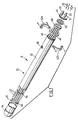
- the principal components of the module are a housing generally indicated by reference numeral 20 and a series or "bundle" of spaced-apart membrane tubes 22 which extend between respective inlet and return headers 24 and 26 in the assembled module.
- Inlet and return pipes for fluid to be treated are indicated respectively at 28 and 30 in Fig. 1.
- Housing 20 includes a plain tubular shell 32 which is closed at one end by an end cap 34 and at the other by the inlet header 24.
- the shell 32 is a length of standard circular section PVC pipe.
- the end cap 34 is made of the same material and is permanently secured to shell 32 by a suitable solvent cement. Permeate outlets from housing 20 is provided by threaded ports 36 in shell 32.
- Inlet header 24 has the overall shape of a circular disc (see Fig. 3) of the same diameter as shell 32 and is secured across the end of the shell opposite end cap 34 (Fig. 2).
- the inlet header is mechanically attached and sealed to shell 32 by a VICTAULIC (TM) clamp generally denoted by reference numeral 38.
- Clamp 38 includes an annular seal member 40 which encircles the joint line between shell 32 and inlet header 24, and an outer bracket indicated at 42 which embraces the seal member 40 and which has inwardly directed flanges that engage in respective grooves 44 and 46 in header 24 and shell 32.
- bracket 42 is in fact made up of two C-shaped members 42a and 42b which are bolted together.
- Return header 26 also has the overall shape of a circular disc but is of somewhat less diameter than the inlet header 24. Return header is sized to fit closely within the shell 32 of module housing 20 but is free to float longitudinally of the module, as indicated by the arrow 48 in Fig. 2.
- the two headers 24, 26 are both moulded in a PVC material and are shaped to provide on their respective inner surfaces return fluid passageways configured to permit fluid to flow through the membrane tubes 22 in series.
- the inner surface of inlet header 24 is shown in Fig. 3 and is denoted by reference numeral 24a while the inner surface of return header 26 is shown in Fig. 4 and is denoted 26a.
- Inlet header 24 has respective inlet and outlet ports 50 and 52 which communicate with the inlet and outlet pipes 28 and 30 respectively shown in Fig. 1 when the module is in use.
- the return fluid passageways are individually denoted by reference numeral 54 and it will be seen that three such passageways are provided in the case of inlet header 24.
- Return header 26 has no ports but has four return fluid passageways individually denoted at 56.
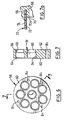
- Fig. 5 is an artificial view in the direction of arrow C in Fig. 2 and shows in full lines the ports 50, 52 (Fig. 3) and return passageways 54 of the inlet header 24 super-imposed on the passageways 56 of the return header 26 (which are shown in dotted lines).
- This view illustrates quite graphically how the ports and passageways cooperate to provide for series flow of fluid through the membrane tubes 22.
- FIG. 5 shows the ports and passageways of inlet header 24 in mirror image as compared with Fig. 3 because those ports and passageways are illustrated as they would be seen in the direction of arrow C (i.e. from the outer end of inlet header 24).
- the particular configuration of ports and passageways shown in the drawings is designed to accomodate eight membrane tubes arranged with one tube at the centre and the remainder equiangularly spaced around the centre tube.
- the number of tubes and, consequently, the configuration and arrangement of return fluid passageways may of course vary. In another practical embodiment, a module having twenty tubes is provided.
- potting collars are used to couple the tubes to the respective headers.
- the potting collars are identical and are individually denoted by reference numeral 58 in Fig. 2.
- One of those collars is shown separately in Figs. 6, 7 and 7a. Again, the component is a disc-shaped PVC moulding.
- the potting collar has an inner face 60 at which the tubes are coupled to the collar, and an outer face 62 which bears against the inner face of the relevant header 24 or 26 in the assembled module.
- the inner face 60 of the collar is formed with a series of sockets 64 for receiving the membrane tubes.
- the sockets are of course arranged in a configuration corresponding to the configuration of the tubes in the bundle; that is, with a single centre tube and seven further tubes equiangularly spaced around the centre tube as shown in Fig. 6.
- each socket 64 has an annular blind end 66 for closely receiving an end portion of one of the tubes 22.
- a port 68 of smaller diameter than and located within the blind end portion 64 of the socket provides communication between the interior of the tube and the header in the assembled module.
- Fig. 7a shows an enlarged detail of part of the annular blind end of one of the sockets 66 and part of one of the tubes 22 in place in the socket.
- the tubes are sealed into the sockets by an appropriate epoxy resin.
- the blind end 66 of socket 64 in effect forms an undercut with respect to the port 68, leaving a shoulder 70 between the port and the tube.
- Shoulder 70 is radiussed at 70a to facilitate insertion of the tubes into the sockets.
- Shoulder 70 in effect protects the tube from the effects of fluid shear caused by fluid entering the tube 22 from the port 68 under pressure. The fluid shear effect could otherwise cause the membrane to be stripped from the inner surface of tube 22.
- Fig. 7a shows an enlarged detail of part of the annular blind end of one of the sockets 66 and part of one of the tubes 22 in place in the socket.
- the tubes are sealed into the sockets by an appropriate epoxy resin.
- the membrane is denoted by reference numeral 72 and is illustrated as having an exaggerated thickness.
- the membrane is cast on to the inner surface of a glass fibre-reinforced fabric pipe 74 by a technique that is well-known in the art.
- the pipe itself has not been illustrated in detail since it too may be of conventional form.
- the pipe may comprise several layers of spirally wound fabric tapes. These may be filament wound with glass fibres impregnated with a suitable thermosetting plastic resin, when extra strength is required.
- potting collars 58 allows the bundle of tubes and collars to be preformed as a sub-assembly to which the respective headers 24 and 26 are subsequently attached.
- mechanical attachment is used.
- a series of socket-headed cap screws which are individually denoted by reference numeral 76 in Fig. 2 are inserted through preformed holes in the respective headers and driven into the respective potting collars in the manner of self-tapping screws.
- Preformed holes in the two headers for receiving the screws are indicated at 78 in the case of inlet header 24 (Fig. 3) and at 80 in the case of return header 26 (Fig. 4).
- neoprene gasket is used between each header and potting collar in the assembled module; the two gaskets are indicated at 82 in Fig. 2.
- Fig. 2 also shows tube support baffles or "spiders” 84 which may be used between the potting collars to help protect against sagging or deflection of the tubes due to the weight of fluid, internal pressure or temperature.
- These "spiders” are essentially thin PVC discs having an external diameter slightly less than the internal diameter of the housing shell 32, and each of which is formed with a series of holes for receiving membrane tubes. The holes are dimensioned so that the spiders can frictionally fit onto the tubes. In a very short module, the spiders may be unnecessary, while in longer modules two or even more spiders may be necessary.
- the module 20 shown in the drawings may have an overall nominal length of approximately 2 metres. It will be appreciated that, since the tubes are not made of the same material as the shell, the overall length of the tubes may vary with respect to the shell in response to varying temperature conditions. The fact that the return header 26 is free to float longitudinally accomodates this variation without imposing stresses on the tubes in service. It will also be appreciated that the particular design of the module is economic in the sense that it permits the use of standard pipe sizes for the shell 32.
- Fig. 8 illustrates that it is possible to multiply the capacity of the module by simply using a longer tube for the shell 32 and bolting together end to end two or more sub-assemblies each comprising a series of tubes and a pair of potting collars.
- Primed reference numerals have been used in Fig. 8 to denote parts that correspond with parts shown in the previous views.
- two potting collars 58' of a pair of tube bundle sub-assemblies are bolted together face to face with respective inlet and return headers 24' and 26' at opposite ends of the assembly.
- the potting collars are preformed with holes for receiving such bolts, as indicated at 84 in Figs. 6 and 7. It will be understood from Fig. 8 that the facility for the return header 26' to float longitudinally of the shell 32' is particularly important in an extended module of this form.
Landscapes
- Chemical & Material Sciences (AREA)
- Chemical Kinetics & Catalysis (AREA)
- Separation Using Semi-Permeable Membranes (AREA)
- Ultra Sonic Daignosis Equipment (AREA)
Abstract
Description
- This invention relates to so-called tubular membrane modules used in pressure-driven fluid concentration and/or separation processes. Examples of such processes are microfiltration, ultrafiltration and reverse osmosis.
- The term "tubular membrane module" is used to refer to a component which includes a series of permeable membranes of tubular configuration each supported on the inner surface of a porous pipe such as a glass fibre-reinforced fabric pipe. The pipes are enclosed within an outer housing having a permeate outlet. Fluid to be treated is passed through the pipes under pressure. Permeate passes through the membranes and pipes into the interior of the outer housing and leaves through the permeate outlet.
- US-A-4,707,261 (Ikeyama et al.) discloses a tubular membrane ultrafiltration module in which a plurality of water permeable non-woven fabric pipes are formed on the inside surface of an outer cylinder. The pipes are inserted into the outer cylinder in a closely bundled state and the spaces between the pipes and the outer cylinder at each end are filled with hardened synthetic resin to fix and seal the assembly. In other words, the ultrafiltration module provided by the Ikeyama invention essentially comprises a monolithic structure of non-woven fabric pipes set in an outer cylinder by means of a hardened synthetic resin.
- The invention relates to a tubular membrane module of a type known generally from EP-A-0 217 568, comprising a housing which includes a tubular shell having a closed first end and a permeate outlet, an inlet header sealed to the shell at a second end thereof, a second header disposed within the shell remote from the inlet header, and a plurality of membrane tubes extending between and sealed to the headers. Each tube comprises a porous pipe and a permeable membrane on the inner surface of the pipe. The inlet header has inlet and outlet ports, the return header having a return fluid passageway configured to permit fluid to flow through said membrane tubes in series from the inlet port to the outlet port.
- According to the invention, the ends of the membrane tubes are connected to respective tube potting collars having sockets in which the ends of the tubes are sealed. The thus-assembled membrane tubes and potting collars form a sub-assembly of the module which is connected in the module by attachment of the potting collars to the respective header. In this way, the second header can be made as a floating return header which fits closely within the shell but is free to move longitudinally with respect to the shell when the module is in use.
- This module offers a number of practical advantages in terms of economy of construction, in particular as regards pre-assembling of the tubes and potting collars, and fitting of these sub-assemblies in the module. At the same time, the use of a free-floating return header assembly minimizes stresses on the membrane tubes in service that would otherwise be caused by changes in the length of the tubes due to factors such as temperature variations if a fixed header were employed.
- In order that the invention may be more clearly understood, reference will now be made to the accompanying drawings which illustrate a particular preferred embodiment of the invention by way of example, and in which:
- Fig. 1 is a perspective view, partly exploded and partly broken away, of a tubular membrane module in accordance with a preferred embodiment of the invention;
- Fig. 2 is a vertical sectional view through the module of Fig. 1 as seen in the direction of arrow A;
- Fig. 3 and 4 are elevational views of the inner faces of the respective inlet and return headers of the module;
- Fig. 5 is a diagrammatic illustration showing the passageways in the inlet header superimposed on those of the return header;
- Fig. 6 is an elevational view of one of the tube potting collars used in the module;
- Fig. 7 is a sectional view on line 7-7 of Fig. 6;
- Fig. 7a is a detail view of the part of Fig. 7 circled at B; and,
- Fig. 8 is a view similar to Fig. 1 showing a module of extended length.
- The drawings show a tubular membrane module that was developed particularly for use in microfiltration and ultrafiltration. Referring first to Fig. 1, the principal components of the module are a housing generally indicated by
reference numeral 20 and a series or "bundle" of spaced-apart membrane tubes 22 which extend between respective inlet andreturn headers - Fig. 2 shows the assembled module.
Housing 20 includes a plaintubular shell 32 which is closed at one end by anend cap 34 and at the other by theinlet header 24. In this particular embodiment, theshell 32 is a length of standard circular section PVC pipe. Theend cap 34 is made of the same material and is permanently secured toshell 32 by a suitable solvent cement. Permeate outlets fromhousing 20 is provided by threadedports 36 inshell 32. -
Inlet header 24 has the overall shape of a circular disc (see Fig. 3) of the same diameter asshell 32 and is secured across the end of the shell opposite end cap 34 (Fig. 2). The inlet header is mechanically attached and sealed toshell 32 by a VICTAULIC (TM) clamp generally denoted byreference numeral 38.Clamp 38 includes anannular seal member 40 which encircles the joint line betweenshell 32 andinlet header 24, and an outer bracket indicated at 42 which embraces theseal member 40 and which has inwardly directed flanges that engage inrespective grooves header 24 andshell 32. As can be seen from Fig. 1,bracket 42 is in fact made up of two C-shaped members -
Return header 26 also has the overall shape of a circular disc but is of somewhat less diameter than theinlet header 24. Return header is sized to fit closely within theshell 32 ofmodule housing 20 but is free to float longitudinally of the module, as indicated by thearrow 48 in Fig. 2. - The two
headers membrane tubes 22 in series. Referring more specifically to Figs. 3 and 4, the inner surface ofinlet header 24 is shown in Fig. 3 and is denoted byreference numeral 24a while the inner surface ofreturn header 26 is shown in Fig. 4 and is denoted 26a.Inlet header 24 has respective inlet andoutlet ports outlet pipes inlet header 24.Return header 26 has no ports but has four return fluid passageways individually denoted at 56. - Fig. 5 is an artificial view in the direction of arrow C in Fig. 2 and shows in full lines the
ports 50, 52 (Fig. 3) and return passageways 54 of theinlet header 24 super-imposed on thepassageways 56 of the return header 26 (which are shown in dotted lines). This view illustrates quite graphically how the ports and passageways cooperate to provide for series flow of fluid through themembrane tubes 22. - It will of course be appreciated that Fig. 5 shows the ports and passageways of
inlet header 24 in mirror image as compared with Fig. 3 because those ports and passageways are illustrated as they would be seen in the direction of arrow C (i.e. from the outer end of inlet header 24). It will also be appreciated that the particular configuration of ports and passageways shown in the drawings is designed to accomodate eight membrane tubes arranged with one tube at the centre and the remainder equiangularly spaced around the centre tube. The number of tubes and, consequently, the configuration and arrangement of return fluid passageways may of course vary. In another practical embodiment, a module having twenty tubes is provided. - At opposite ends of the bundle of tubes potting collars are used to couple the tubes to the respective headers. The potting collars are identical and are individually denoted by
reference numeral 58 in Fig. 2. One of those collars is shown separately in Figs. 6, 7 and 7a. Again, the component is a disc-shaped PVC moulding. - As seen in Fig. 7, the potting collar has an
inner face 60 at which the tubes are coupled to the collar, and anouter face 62 which bears against the inner face of therelevant header inner face 60 of the collar is formed with a series ofsockets 64 for receiving the membrane tubes. The sockets are of course arranged in a configuration corresponding to the configuration of the tubes in the bundle; that is, with a single centre tube and seven further tubes equiangularly spaced around the centre tube as shown in Fig. 6. Referring back to Fig. 7, eachsocket 64 has an annularblind end 66 for closely receiving an end portion of one of thetubes 22. Aport 68 of smaller diameter than and located within theblind end portion 64 of the socket provides communication between the interior of the tube and the header in the assembled module. - Fig. 7a shows an enlarged detail of part of the annular blind end of one of the
sockets 66 and part of one of thetubes 22 in place in the socket. The tubes are sealed into the sockets by an appropriate epoxy resin. It will be seen from Fig. 7a that theblind end 66 ofsocket 64 in effect forms an undercut with respect to theport 68, leaving ashoulder 70 between the port and the tube.Shoulder 70 is radiussed at 70a to facilitate insertion of the tubes into the sockets.Shoulder 70 in effect protects the tube from the effects of fluid shear caused by fluid entering thetube 22 from theport 68 under pressure. The fluid shear effect could otherwise cause the membrane to be stripped from the inner surface oftube 22. In Fig. 7a, the membrane is denoted byreference numeral 72 and is illustrated as having an exaggerated thickness. The membrane is cast on to the inner surface of a glass fibre-reinforcedfabric pipe 74 by a technique that is well-known in the art. The pipe itself has not been illustrated in detail since it too may be of conventional form. For example, the pipe may comprise several layers of spirally wound fabric tapes. These may be filament wound with glass fibres impregnated with a suitable thermosetting plastic resin, when extra strength is required. - Referring back to Fig. 2, it will be appreciated that the use of the
potting collars 58 allows the bundle of tubes and collars to be preformed as a sub-assembly to which therespective headers reference numeral 76 in Fig. 2 are inserted through preformed holes in the respective headers and driven into the respective potting collars in the manner of self-tapping screws. Preformed holes in the two headers for receiving the screws are indicated at 78 in the case of inlet header 24 (Fig. 3) and at 80 in the case of return header 26 (Fig. 4). - A neoprene gasket is used between each header and potting collar in the assembled module; the two gaskets are indicated at 82 in Fig. 2. Fig. 2 also shows tube support baffles or "spiders" 84 which may be used between the potting collars to help protect against sagging or deflection of the tubes due to the weight of fluid, internal pressure or temperature. These "spiders" are essentially thin PVC discs having an external diameter slightly less than the internal diameter of the
housing shell 32, and each of which is formed with a series of holes for receiving membrane tubes. The holes are dimensioned so that the spiders can frictionally fit onto the tubes. In a very short module, the spiders may be unnecessary, while in longer modules two or even more spiders may be necessary. - By way of example, the
module 20 shown in the drawings may have an overall nominal length of approximately 2 metres. It will be appreciated that, since the tubes are not made of the same material as the shell, the overall length of the tubes may vary with respect to the shell in response to varying temperature conditions. The fact that thereturn header 26 is free to float longitudinally accomodates this variation without imposing stresses on the tubes in service. It will also be appreciated that the particular design of the module is economic in the sense that it permits the use of standard pipe sizes for theshell 32. - Fig. 8 illustrates that it is possible to multiply the capacity of the module by simply using a longer tube for the
shell 32 and bolting together end to end two or more sub-assemblies each comprising a series of tubes and a pair of potting collars. Primed reference numerals have been used in Fig. 8 to denote parts that correspond with parts shown in the previous views. Thus, it will be seen that two potting collars 58' of a pair of tube bundle sub-assemblies are bolted together face to face with respective inlet and return headers 24' and 26' at opposite ends of the assembly. The potting collars are preformed with holes for receiving such bolts, as indicated at 84 in Figs. 6 and 7. It will be understood from Fig. 8 that the facility for the return header 26' to float longitudinally of the shell 32' is particularly important in an extended module of this form.
Claims (6)
- A tubular membrane module comprising a housing (20) which includes a tubular shell (32) having a closed first end and a permeate outlet (36), an inlet header (24) sealed to said shell (20) at a second end thereof, a second return header (26) disposed within said shell (20) remote from said inlet header (24), and a plurality of membrane tubes (22) extending between and sealed to said headers (24,26), each tube (22) comprising a porous pipe (74) and a permeable membrane (72) on the inner surface of said pipe, said inlet header (24) having inlet and outlet ports (50,52), and at least said return header (26) having a return fluid passageway (56) configured to permit fluid to flow through said membrane tubes (22) in series from said inlet port (50) to said outlet port (52), characterised in that :- the ends of the membrane tubes (22) are connected to respective tube potting collars (58) having sockets (64) in which the ends of the tubes are sealed, said membrane tubes (22) and potting collars (58) forming a sub-assembly of the module which is connected in the module by attachment of the potting collars (58) to the respective header (24,26); and- said second header (26) is a floating return header which is sized to fit closely within said shell (20) but is free to move longitudinally with respect to the shell when the module is in use.
- A module as claimed in claim 1, wherein each potting collar (58) is mechanically coupled in pressure-tight fashion to an inner face (24a, 26a) of the respective header, and at least an inlet end portion of each membrane tube (22) is sealed in a socket (64) having an annular blind end (66) closely receiving said end portion of the respective tube (22), and a port (68) of smaller diameter than and within said blind end (66) providing communication between the interior of the tube (22) and the header (24,26), whereby the membrane (72) on the tube (22) is protected from fluid shear caused by fluid entering the tube from the header under pressure.
- A module as claimed in claim 1 or 2, wherein the module comprises a plurality of said sub-assemblies of membrane tubes and potting collars coupled together end-to-end between said inlet and return headers (24',26'), the tubes (22') in respective sub-assemblies being aligned with one another, and wherein said tubular shell (32') comprises a length of plastic tubing selected to accommodate said sub-assemblies.
- A module as claimed in claim 1, wherein said shell (32) comprises a length of standard plastic pipe, and wherein said inlet header (24) has the overall shape of a disc of substantially the same external diameter as the diameter of the shell and is coupled to the shell over said second end by an external clamp (38) which includes an annular seal (40) encircling the joint between the shell and the inlet header, and a bracket (42) enclosing said seal (40).
- A module as claimed in claim 1, wherein said shell (32) comprises a length of plastic tube, and wherein said inlet and return headers (24,26) each comprise a disc-shaped plastic moulding.
- A module as claimed in claim 1, further comprising at least one membrane tube support baffle (84) disposed in said shell (32) between the headers (24,26), the tubes (22) passing through the baffle (84) and the baffle (84) being dimensioned to fit closely within said shell.
Applications Claiming Priority (2)
| Application Number | Priority Date | Filing Date | Title |
|---|---|---|---|
| US199823 | 1988-05-27 | ||
| US07/199,823 US4897191A (en) | 1988-05-27 | 1988-05-27 | Tubular membrane module with fluid shear protection |
Publications (3)
| Publication Number | Publication Date |
|---|---|
| EP0343895A2 EP0343895A2 (en) | 1989-11-29 |
| EP0343895A3 EP0343895A3 (en) | 1990-01-31 |
| EP0343895B1 true EP0343895B1 (en) | 1995-03-08 |
Family
ID=22739175
Family Applications (1)
| Application Number | Title | Priority Date | Filing Date |
|---|---|---|---|
| EP89305145A Expired - Lifetime EP0343895B1 (en) | 1988-05-27 | 1989-05-22 | Tubular membrane module |
Country Status (7)
| Country | Link |
|---|---|
| US (1) | US4897191A (en) |
| EP (1) | EP0343895B1 (en) |
| JP (1) | JPH0226624A (en) |
| AT (1) | ATE119427T1 (en) |
| AU (1) | AU618597B2 (en) |
| CA (1) | CA1321549C (en) |
| DE (1) | DE68921509T2 (en) |
Families Citing this family (20)
| Publication number | Priority date | Publication date | Assignee | Title |
|---|---|---|---|---|
| JPH0829228B2 (en) * | 1988-08-12 | 1996-03-27 | ダイセル化学工業株式会社 | Tubular membrane module for separation |
| US5227063A (en) * | 1989-10-03 | 1993-07-13 | Zenon Environmental Inc. | Tubular membrane module |
| US5100549A (en) * | 1990-03-26 | 1992-03-31 | Zenon Environmental Inc. | Tubular membrane module |
| US5176725A (en) * | 1991-07-26 | 1993-01-05 | Air Products And Chemicals, Inc. | Multiple stage countercurrent hollow fiber membrane module |
| DE9206870U1 (en) * | 1992-05-21 | 1993-06-17 | WAP Reinigungssysteme GmbH & Co, 7919 Bellenberg | Tube module for ultrafiltration |
| FR2697886B1 (en) * | 1992-11-12 | 1994-12-30 | Tech Sep | Elastomer seal for filtration module. |
| GB9418578D0 (en) * | 1994-09-15 | 1994-11-02 | Britsh Nuclear Fuels Plc | Liquid filtration apparatus |
| US6027649A (en) * | 1997-04-14 | 2000-02-22 | Zenon Environmental, Inc. | Process for purifying water using fine floc and microfiltration in a single tank reactor |
| DE10227721B4 (en) * | 2002-06-21 | 2008-03-13 | Hermsdorfer Institut Für Technische Keramik E.V. | Process for producing a bundle of ceramic capillaries for a separation module |
| DE10323440B4 (en) * | 2003-05-23 | 2006-10-26 | Sulzer Chemtech Gmbh - Membrantechnik - | Membrane tube module |
| US20070193739A1 (en) * | 2005-02-14 | 2007-08-23 | Smith Kevin W | Scale-inhibited water reduction in solutions and slurries |
| DE102006060858A1 (en) | 2006-12-22 | 2008-09-04 | Fachhochschule Köln | Ceramic filter to separate over critical gasses from adsorbed compounds has ceramic tubes clamped each end with axial movement |
| KR102178191B1 (en) | 2008-09-02 | 2020-11-13 | 머크 밀리포어 리미티드 | Chromatography membranes, devices containing them, and methods of use thereof |
| JP4929269B2 (en) * | 2008-11-13 | 2012-05-09 | 三菱重工業株式会社 | Membrane container |
| US9873088B2 (en) | 2011-05-17 | 2018-01-23 | Natrix Separations Inc. | Layered tubular membranes for chromatography, and methods of use thereof |
| TWI558953B (en) * | 2013-10-25 | 2016-11-21 | 建準電機工業股份有限公司 | Heat exchanger of ventilation apparatus |
| US20150246305A1 (en) * | 2014-03-02 | 2015-09-03 | Johannes A. Thomassen | Plastic membrane housing for ceramic membranes |
| JP6519874B2 (en) * | 2015-11-18 | 2019-05-29 | 三菱重工環境・化学エンジニアリング株式会社 | Water treatment system |
| CN106964259B (en) * | 2017-05-18 | 2019-07-02 | 许劲松 | A kind of air cleaning membrane separation device and preparation method thereof |
| CN110508150B (en) * | 2019-09-27 | 2024-06-25 | 李俊宏 | Tubular membrane filtration sealing piece with high filtration efficiency |
Family Cites Families (12)
| Publication number | Priority date | Publication date | Assignee | Title |
|---|---|---|---|---|
| US2353489A (en) * | 1942-07-06 | 1944-07-11 | Raymond I Newcomb | Apparatus for releasing the fibers from straw or other fibrous material |
| US3392840A (en) * | 1965-12-28 | 1968-07-16 | Universal Walter Corp | Tubular reverse osmosis apparatus |
| US3485374A (en) * | 1968-05-09 | 1969-12-23 | Serop Manjikian | Reverse osmosis module |
| US3716143A (en) * | 1970-03-30 | 1973-02-13 | Aqua Chem Inc | Reverse osmosis separation apparatus |
| US3710946A (en) * | 1971-05-18 | 1973-01-16 | Calgon Corp | Welded connectors for tubular separator module |
| US3774771A (en) * | 1971-12-09 | 1973-11-27 | Interior | Reverse osmosis module |
| US3817387A (en) * | 1973-07-30 | 1974-06-18 | Philco Ford Corp | Reverse osmosis membrane end fitting |
| US4309287A (en) * | 1980-05-01 | 1982-01-05 | Abcor, Inc. | Reverse-osmosis tubular membrane |
| JPS5986204A (en) * | 1982-11-09 | 1984-05-18 | Agency Of Ind Science & Technol | magnetic material |
| JPS614508A (en) * | 1984-06-15 | 1986-01-10 | Agency Of Ind Science & Technol | Method for sealing terminal end of bundle of thin tube |
| GB8523549D0 (en) * | 1985-09-24 | 1985-10-30 | Atomic Energy Authority Uk | Liquid treatment apparatus |
| US4707267A (en) * | 1987-01-22 | 1987-11-17 | The Dow Chemical Company | Device and method for separating individual fluids from a mixture of fluids |
-
1988
- 1988-05-27 US US07/199,823 patent/US4897191A/en not_active Expired - Lifetime
-
1989
- 1989-05-12 AU AU34741/89A patent/AU618597B2/en not_active Ceased
- 1989-05-22 EP EP89305145A patent/EP0343895B1/en not_active Expired - Lifetime
- 1989-05-22 AT AT89305145T patent/ATE119427T1/en not_active IP Right Cessation
- 1989-05-22 DE DE68921509T patent/DE68921509T2/en not_active Expired - Fee Related
- 1989-05-25 CA CA000600723A patent/CA1321549C/en not_active Expired - Fee Related
- 1989-05-26 JP JP1134434A patent/JPH0226624A/en active Pending
Non-Patent Citations (1)
| Title |
|---|
| Perry's Chemical Engineer's Handbook, 5th edition page 11-9, figs, 11-2(a),(c). * |
Also Published As
| Publication number | Publication date |
|---|---|
| AU618597B2 (en) | 1992-01-02 |
| DE68921509T2 (en) | 1995-12-07 |
| US4897191A (en) | 1990-01-30 |
| AU3474189A (en) | 1990-03-22 |
| ATE119427T1 (en) | 1995-03-15 |
| JPH0226624A (en) | 1990-01-29 |
| CA1321549C (en) | 1993-08-24 |
| EP0343895A2 (en) | 1989-11-29 |
| EP0343895A3 (en) | 1990-01-31 |
| DE68921509D1 (en) | 1995-04-13 |
Similar Documents
| Publication | Publication Date | Title |
|---|---|---|
| US4897191A (en) | Tubular membrane module with fluid shear protection | |
| US5227063A (en) | Tubular membrane module | |
| KR102502797B1 (en) | Flexible adjustable membrane cartridges for separation of fluids | |
| EP0525317B1 (en) | An apparatus for effecting mass and/or heat transfer | |
| US4670145A (en) | Multiple bundle fluid separation apparatus | |
| US4461707A (en) | Ultrafiltration and reverse osmosis tubular membrane module | |
| US7311830B2 (en) | Filtration element and method of constructing a filtration assembly | |
| KR102532833B1 (en) | Hollow fibre membrane cartridge and module for the separation of fluids | |
| EP0873779B1 (en) | Permselective membrane module | |
| EP0053635A1 (en) | Hollow fiber assembly having selective permeability | |
| CA2046987A1 (en) | Multiple bundle fluid separation apparatus | |
| US4632756A (en) | Multiple bundle separatory module | |
| US5100549A (en) | Tubular membrane module | |
| JPS647804B2 (en) | ||
| AU745678B2 (en) | Joint structure for filtration membrane module | |
| CA2117869C (en) | Spiral filtration module having bypass prevention flange | |
| EP0226431B1 (en) | Hollow fiber separatory module | |
| US3710946A (en) | Welded connectors for tubular separator module | |
| US3786925A (en) | Means for sealing membrane carrying tubes | |
| US4846973A (en) | Membrane tube filter device and disc supports and tension members | |
| US3834545A (en) | Supported tubular membrane | |
| US4959149A (en) | Multiple tube series membrane filtration module and method of preparing same | |
| US20030029786A1 (en) | Modular filter housing | |
| JP3070998B2 (en) | Method for manufacturing hollow fiber membrane separation module and hollow fiber membrane separation module | |
| US20240042386A1 (en) | Liquid purification system |
Legal Events
| Date | Code | Title | Description |
|---|---|---|---|
| PUAI | Public reference made under article 153(3) epc to a published international application that has entered the european phase |
Free format text: ORIGINAL CODE: 0009012 |
|
| AK | Designated contracting states |
Kind code of ref document: A2 Designated state(s): AT BE CH DE ES FR GB GR IT LI LU NL SE |
|
| PUAL | Search report despatched |
Free format text: ORIGINAL CODE: 0009013 |
|
| AK | Designated contracting states |
Kind code of ref document: A3 Designated state(s): AT BE CH DE ES FR GB GR IT LI LU NL SE |
|
| 17P | Request for examination filed |
Effective date: 19900719 |
|
| 17Q | First examination report despatched |
Effective date: 19920207 |
|
| GRAA | (expected) grant |
Free format text: ORIGINAL CODE: 0009210 |
|
| AK | Designated contracting states |
Kind code of ref document: B1 Designated state(s): AT BE CH DE ES FR GB GR IT LI LU NL SE |
|
| PG25 | Lapsed in a contracting state [announced via postgrant information from national office to epo] |
Ref country code: AT Effective date: 19950308 Ref country code: CH Effective date: 19950308 Ref country code: GR Free format text: LAPSE BECAUSE OF FAILURE TO SUBMIT A TRANSLATION OF THE DESCRIPTION OR TO PAY THE FEE WITHIN THE PRESCRIBED TIME-LIMIT Effective date: 19950308 Ref country code: BE Effective date: 19950308 Ref country code: ES Free format text: THE PATENT HAS BEEN ANNULLED BY A DECISION OF A NATIONAL AUTHORITY Effective date: 19950308 Ref country code: LI Effective date: 19950308 |
|
| REF | Corresponds to: |
Ref document number: 119427 Country of ref document: AT Date of ref document: 19950315 Kind code of ref document: T |
|
| REF | Corresponds to: |
Ref document number: 68921509 Country of ref document: DE Date of ref document: 19950413 |
|
| PG25 | Lapsed in a contracting state [announced via postgrant information from national office to epo] |
Ref country code: LU Free format text: LAPSE BECAUSE OF NON-PAYMENT OF DUE FEES Effective date: 19950531 |
|
| ITF | It: translation for a ep patent filed | ||
| PG25 | Lapsed in a contracting state [announced via postgrant information from national office to epo] |
Ref country code: SE Effective date: 19950608 |
|
| REG | Reference to a national code |
Ref country code: CH Ref legal event code: PL |
|
| ET | Fr: translation filed | ||
| K2C3 | Correction of patent specification (complete document) published |
Effective date: 19950308 |
|
| PLBE | No opposition filed within time limit |
Free format text: ORIGINAL CODE: 0009261 |
|
| STAA | Information on the status of an ep patent application or granted ep patent |
Free format text: STATUS: NO OPPOSITION FILED WITHIN TIME LIMIT |
|
| 26N | No opposition filed | ||
| PGFP | Annual fee paid to national office [announced via postgrant information from national office to epo] |
Ref country code: FR Payment date: 20010611 Year of fee payment: 13 |
|
| PGFP | Annual fee paid to national office [announced via postgrant information from national office to epo] |
Ref country code: GB Payment date: 20010613 Year of fee payment: 13 |
|
| PGFP | Annual fee paid to national office [announced via postgrant information from national office to epo] |
Ref country code: DE Payment date: 20010618 Year of fee payment: 13 |
|
| PGFP | Annual fee paid to national office [announced via postgrant information from national office to epo] |
Ref country code: NL Payment date: 20010628 Year of fee payment: 13 |
|
| REG | Reference to a national code |
Ref country code: GB Ref legal event code: IF02 |
|
| PG25 | Lapsed in a contracting state [announced via postgrant information from national office to epo] |
Ref country code: GB Free format text: LAPSE BECAUSE OF NON-PAYMENT OF DUE FEES Effective date: 20020522 |
|
| PG25 | Lapsed in a contracting state [announced via postgrant information from national office to epo] |
Ref country code: NL Free format text: LAPSE BECAUSE OF NON-PAYMENT OF DUE FEES Effective date: 20021201 |
|
| PG25 | Lapsed in a contracting state [announced via postgrant information from national office to epo] |
Ref country code: DE Free format text: LAPSE BECAUSE OF NON-PAYMENT OF DUE FEES Effective date: 20021203 |
|
| GBPC | Gb: european patent ceased through non-payment of renewal fee |
Effective date: 20020522 |
|
| NLV4 | Nl: lapsed or anulled due to non-payment of the annual fee |
Effective date: 20021201 |
|
| PG25 | Lapsed in a contracting state [announced via postgrant information from national office to epo] |
Ref country code: FR Free format text: LAPSE BECAUSE OF NON-PAYMENT OF DUE FEES Effective date: 20030331 |
|
| REG | Reference to a national code |
Ref country code: FR Ref legal event code: ST |
|
| PG25 | Lapsed in a contracting state [announced via postgrant information from national office to epo] |
Ref country code: IT Free format text: LAPSE BECAUSE OF NON-PAYMENT OF DUE FEES Effective date: 20050522 |
|
| PG25 | Lapsed in a contracting state [announced via postgrant information from national office to epo] |
Ref country code: FR Free format text: LAPSE BECAUSE OF NON-PAYMENT OF DUE FEES Effective date: 20020531 |
|
| P01 | Opt-out of the competence of the unified patent court (upc) registered |
Effective date: 20230521 |