EP0340164A1 - Device for redistributing food discs from a first onto a second transport organ - Google Patents
Device for redistributing food discs from a first onto a second transport organ Download PDFInfo
- Publication number
- EP0340164A1 EP0340164A1 EP89810272A EP89810272A EP0340164A1 EP 0340164 A1 EP0340164 A1 EP 0340164A1 EP 89810272 A EP89810272 A EP 89810272A EP 89810272 A EP89810272 A EP 89810272A EP 0340164 A1 EP0340164 A1 EP 0340164A1
- Authority
- EP
- European Patent Office
- Prior art keywords
- biscuits
- columns
- rail
- supports
- section
- Prior art date
- Legal status (The legal status is an assumption and is not a legal conclusion. Google has not performed a legal analysis and makes no representation as to the accuracy of the status listed.)
- Granted
Links
Images

Classifications
-
- B—PERFORMING OPERATIONS; TRANSPORTING
- B65—CONVEYING; PACKING; STORING; HANDLING THIN OR FILAMENTARY MATERIAL
- B65G—TRANSPORT OR STORAGE DEVICES, e.g. CONVEYORS FOR LOADING OR TIPPING, SHOP CONVEYOR SYSTEMS OR PNEUMATIC TUBE CONVEYORS
- B65G47/00—Article or material-handling devices associated with conveyors; Methods employing such devices
- B65G47/74—Feeding, transfer, or discharging devices of particular kinds or types
- B65G47/94—Devices for flexing or tilting travelling structures; Throw-off carriages
- B65G47/96—Devices for tilting links or platform
- B65G47/967—Devices for tilting links or platform tilting about an axis perpendicular to the conveying direction
-
- B—PERFORMING OPERATIONS; TRANSPORTING
- B65—CONVEYING; PACKING; STORING; HANDLING THIN OR FILAMENTARY MATERIAL
- B65B—MACHINES, APPARATUS OR DEVICES FOR, OR METHODS OF, PACKAGING ARTICLES OR MATERIALS; UNPACKING
- B65B23/00—Packaging fragile or shock-sensitive articles other than bottles; Unpacking eggs
- B65B23/10—Packaging biscuits
- B65B23/12—Arranging, feeding or orientating the biscuits to be packaged
Definitions
- biscuits in a large number of columns they are passed flat on a conveyor belt through a continuous oven. After exiting the oven, the biscuits are cooled and fed to the packaging machines via further transport devices. For example, counted stacks of biscuits are formed in front of the packaging machine. There are often differences between the different columns of biscuits. For example, the biscuits in the peripheral zones are often baked more than the others. There are also differences in the weight of the biscuits between the individual columns. If the biscuits are now packaged in small quantities, there is often only one biscuit in one package and only a few in the other packaging, and the net weights scatter relatively strongly. To prevent this, it is beneficial if everyone ver gripping stacks of biscuits from all columns of the conveyor belt.
- the invention has for its object to develop a device according to the preamble of claim 1 such that it works reliably even with irregular spacing of the food slices within the first columns, and that the handling of the slices with suction and blown air is avoided. This object is achieved by the characterizing features of claim 1.
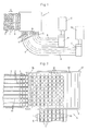
- biscuits 1 are delivered in a first number of columns 2 on a conveyor belt 3 in the conveying direction A of a redistribution device 4 from a continuous oven (not shown).
- the device 4 forms rows of biscuits 1 of the belt 3, a second number of second columns 5 on a second conveyor belt 6 running transversely to the belt 3 in the direction B from the belt 6, the biscuits 1 are transferred to a curved conveyor belt 7. From this belt 7, the biscuits 1 arrive in vibrating conveyor troughs 8, in which they are placed upright and are closed to one another on the flat side. Portioning devices 9 adjoin the channels 8, in which measured biscuit stacks are formed. These are finally packed in packaging machines 10.
- the device 4 is shown in plan view.
- the individual columns 2, 5 on the belts 3, 6 are separated from one another by guide plates 14, 15.
- the biscuits 1 are stowed on the belt 3, so that the biscuits 1 located on a transfer plate 16 form a row and are pushed against a rotating conveyor element 17.
- the conveyor member 17 consists of two lateral, circumferential, endless chains 18 and support plates 19 articulated on these chains 18 at regular intervals and stops 20 projecting outwards (FIGS. 3 to 8).
- the attacks 20 form one-piece extensions of the support plates 19 which are angled by 90 °.
- the plates 19 are connected to the chains 18 at their front end in the conveying direction A about horizontal axes 21 so as to be pivotable.
- each plate 19 has at least on one side a guide roller 22 (FIG. 9) which rotates on a guide rail.
- the chains 18 run obliquely upwards in a first section 26, and then horizontally across the conveyor belt 6 in a second section 27.
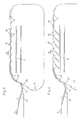
- the plates 19 are inclined obliquely upwards and, together with the stops 20 in longitudinal section according to FIG. 3, form a sawtooth shape.
- the plates 19 in the basic position (FIG. 3) are inclined slightly backwards downward, so that the biscuits 1 lying on them rest against the next stops 20.
- a number of plates 19 corresponding to the number of columns 5 to be formed can simultaneously be pivoted downward about their axes 21 (FIG. 4), so that the biscuits 1 lying on them slide onto the conveyor belt 6.
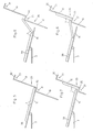
- the last section 28 of the belt 3 and the plate 16 are inclined slightly downwards, with an inclination corresponding approximately to the inclination of the stops 20 in the section 26 of the chains 18 5 to 8 is the transfer of the biscuits 1 to the conveyor organ 17 shown in section 26 in successive steps.
- the outwardly projecting width of the stops 20 is substantially less than half the width of the biscuits 1, so that the foremost biscuit 1 is only raised by the stop 20 at its front edge (FIG. 5).
- the subsequent biscuit 1 pushes the raised biscuit against the next support plate 19 (FIG. 6).
- the next stop 20 now lifts the front edge of the next biscuit 1 (FIGS. 7 and 8).
- the mechanism for lowering the plates 19 in section 27 is shown in Figs. 9-12.
- the guide rail 32 on which the rollers 22 roll has a plurality of inserts 33.
- the number of inserts 33 corresponds to the maximum number of columns 5 and their length corresponds to the distance between adjacent axes 21 or stops 20 from one another.
- At least some consecutive of the inserts 33 have depressions 34 that are aligned with the baffles 15.
- a second rail 35 is arranged next to the inserts 33.
- the rail 35 has a straight running surface 36. It is pivotally mounted on a lever 37 about a horizontal axis 38 on a support 39. A straight, horizontal guide rail 40 for the chain 18 is also fastened to the carrier 39 in the section 27.
- the lever 37 can be pivoted by a pneumatic cylinder 41 from the basic position shown in FIG. 10 into the second position according to FIG. 12.
- the running surface 36 is directly next to the inserts 33, so that the rollers 22 run with their outer halves on the second rail 35 and are held up when the depressions 34 are passed over.
- the rollers 22 In the second position of the rail 35 (FIG. 12), on the other hand, the rollers 22 only run on the rail 32 with their inserts 33 and pass through the depressions 34.
- the cycle frequency of the actuation of the cylinder 41 depends on the number of columns 5 n columns 5, the cylinder 41 is actuated in each case by a distance n times the length of the inserts 33 traveled by the conveying member 17.
- any number of columns 5 is formed from any number of columns 2, each of these second columns 5 biscuits from contains all first columns 2.
- the scattering of the net weights of the packaged stacks is kept low in the packaging machines 10, and the packaged biscuits have approximately the same average degree of browning in all packs.
- the biscuits 1 are handled gently by the device 4 described.
- the device 4 also works perfectly when the biscuits 1 are delivered on the conveyor belt 3 at irregular intervals.
- the number of second columns 5 can be selected as desired, in that the inserts 33 can be exchanged for other inserts with a straight running surface, that is to say without a depression 34.
- the inserts 33 are releasably attached to a console 42.
- the device 4 described it is also possible, as is indicated in FIG. 1, to divide the biscuits 1 from a feed conveyor belt 3 onto a plurality of packaging machines 10 and to adapt the division ratio during operation to the capacity of the packaging machines 10.
- one of several packaging machines 10 can be a reserve packaging machine that normally stands still and is only put into operation when another one fails.
- the rail 35 is divided into segments several times the length of the inserts 33, each segment having its own actuating cylinder 41.
- the cross conveyor belt 6 can be driven in both directions, e.g. in one direction the packaging machines 10, in the opposite direction e.g. a store or a reserve packaging machine can be loaded. If the transverse conveyor belt 6 stops, the biscuits 1 can be conveyed into a waste container or onto another storage belt transporting in the direction A with the conveying member 17.
Abstract
Description
Biskuits werden bei der Herstellung in einer grossen Anzahl von Kolonnen auf einem Förderband flachliegend durch einen Durchlauf-Backofen geführt. Nach dem Austritt aus dem Backofen werden die Biskuits gekühlt und über weitere Transporteinrichtungen den Verpackungsmaschinen zugeführt. Vor der Verpackungsmaschine werden z.B. abgezählte Stapel von Biskuits gebildet. Häufig treten Unterschiede zwischen den verschiedenen Kolonnen von Biskuits auf. So sind beispielsweise die Biskuits in den Randzonen oft stärker durchgebacken als die andern. Auch kommen Gewichtsunterschiede der Biskuits zwischen den einzelnen Kolonnen vor. Werden die Biskuits nun in kleinen Mengen verpackt, so sind oft in einer Verpackung nur stark und in einer andern Verpackung nur wenig durchgebackene Biskuits vorhanden und die Nettogewichte streuen relativ stark. Um dies zu verhindern, ist es vorteilhaft, wenn jeder zu ver packende Stapel Biskuits von sämtlichen Kolonnen des Förderbandes erhält. Zu diesem Zweck ist es aus der EP-A-230'293 bekannt, die vom Förderband angelieferten Biskuits mit Saugnäpfen zu ergreifen, die auf einem Saugförderband befestigt sind. Unterhalb dieses Saugförderbandes verläuft ein weiteres Förderband quer zur Transportrichtung des ersten Förderbandes. Wenn mehrere Reihen von mit den Saugnäpfen gehaltenen Biskuits über dem zweiten Förderband angelangt sind, werden durch einen Schieber die zugehörigen Saugnäpfe mit Blasluft verbunden und damit fallen die Biskuits auf das zweite Band. Die dabei auf dem zweiten Band gebildeten Kolonnen von Biskuits sind Reihen auf dem ersten Band. Jede Kolonne des zweiten Bandes enthält also Biskuits aus sämtlichen Kolonnen des ersten Bandes.In the production of biscuits in a large number of columns, they are passed flat on a conveyor belt through a continuous oven. After exiting the oven, the biscuits are cooled and fed to the packaging machines via further transport devices. For example, counted stacks of biscuits are formed in front of the packaging machine. There are often differences between the different columns of biscuits. For example, the biscuits in the peripheral zones are often baked more than the others. There are also differences in the weight of the biscuits between the individual columns. If the biscuits are now packaged in small quantities, there is often only one biscuit in one package and only a few in the other packaging, and the net weights scatter relatively strongly. To prevent this, it is beneficial if everyone ver gripping stacks of biscuits from all columns of the conveyor belt. For this purpose it is known from EP-A-230,293 to grip the biscuits supplied by the conveyor belt with suction cups which are fastened on a suction conveyor belt. Below this suction conveyor belt, another conveyor belt runs transversely to the direction of transport of the first conveyor belt. If several rows of biscuits held with the suction cups have reached the second conveyor belt, the associated suction cups are connected with blown air by means of a slide and the biscuits fall onto the second belt. The columns of biscuits formed on the second band are rows on the first band. Each column of the second volume contains biscuits from all columns of the first volume.
Mit der in EP-A-230'293 gezeigten Vorrichtung gelingt zwar das gewünschte Mischen der Kolonnen, doch setzt diese bekannte Vorrichtung voraus, dass die Biskuits auf dem ersten Förderband in regelmässigen Abständen angeliefert werden, was häufig nicht der Fall ist. Ausserdem wirbelt der Saug- und Blasbetrieb viel Staub auf, was unerwünscht ist.Although the desired mixing of the columns succeeds with the device shown in EP-A-230,293, this known device requires that the biscuits are delivered on the first conveyor belt at regular intervals, which is often not the case. In addition, the suction and blowing mode whirls up a lot of dust, which is undesirable.
Weitere Vorrichtungen zum Umverteilen von Biskuits sind in der US-PS 3,324,987 und in der CH-PS 657'829 beschrieben.Further devices for redistributing biscuits are described in US Pat. No. 3,324,987 and in CH Pat. No. 657,829.
Der Erfindung liegt die Aufgabe zugrunde, eine Vorrichtung gemäss Oberbegriff des Anspruchs 1 derart weiterzubilden, dass sie auch bei unregelmässigen Abständen der Nahrungsmittelscheiben innerhalb der ersten Kolonnen betriebssicher arbeitet, und dass das Handhaben der Scheiben mit Saug- und Blasluft vermieden wird. Diese Aufgabe wird durch die kennzeichnenden Merkmale des Anspruchs 1 gelöst.The invention has for its object to develop a device according to the preamble of
Nachfolgend wird ein Ausführungsbeispiel der Erfindung anhand der Zeichnung erläutert. Darin zeigt:
- Fig. 1 einen schematischen Grundriss einer Transport- und Verpackungsanordnung,
- Fig. 2 eine Draufsicht auf eine Umverteilungsvorrichtung,
- Fig. 3 und Fig. 4 einen Längsschnitt durch die Vorrichtung nach Fig. 3 in zwei Betriebsstellungen,
- Fig. 5 bis Fig. 8 die Uebergabestelle vom ersten Transportband in aufeinanderfolgenden Stellungen,
- Fig. 9 eine Ansicht eines Details,
- Fig. 10 einen Schnitt längs der Linie X - X in Fig. 9, und
- Fig. 11 und Fig. 12 die den
Figuren 9 und 10 entsprechende Darstellung bei abgesenkten Auflageplatten.
- 1 is a schematic plan view of a transport and packaging arrangement,
- 2 shows a plan view of a redistribution device,
- 3 and FIG. 4 shows a longitudinal section through the device according to FIG. 3 in two operating positions,
- 5 to 8 the transfer point from the first conveyor belt in successive positions,
- 9 is a view of a detail,
- Fig. 10 is a section along the line X - X in Fig. 9, and
- 11 and FIG. 12 the representation corresponding to FIGS. 9 and 10 with the support plates lowered.
Bei der Anlage nach Fig. 1 werden aus einem nicht dargestellten Durchlauf-Backofen Biskuits 1 in einer ersten Anzahl von Kolonnen 2 auf einem Förderband 3 in Förderrichtung A einer Umverteilungsvorrichtung 4 angeliefert. Die Vorrichtung 4 bildet aus Reihen von Biskuits 1 des Bandes 3 eine zweite Anzahl zweiter Kolonnen 5 auf einem quer zum Band 3 in Richtung B laufenden zweiten Förderband 6. Vom Band 6 werden die Biskuits 1 einem Kurvenförderband 7 übergeben. Von diesem Band 7 gelangen die Biskuits 1 in Vibrationsförderrinnen 8, in welchen sie hochkant aufgestellt und flachseitig aneinander geschlossen werden. An die Rinnen 8 schliessen Portioniereinrichtungen 9 an, in welchen abgemessene Biskuitstapel gebildet werden. Diese werden schliesslich in Verpackungsmaschinen 10 verpackt.1,
In Fig. 2 ist die Vorrichtung 4 in der Draufsicht dargestellt. Die einzelnen Kolonnen 2, 5 auf den Bändern 3, 6 sind durch Leitbleche 14, 15 voneinander getrennt. Stromaufwärts der Uebergabestelle an die Vorrichtung 4 werden die Biskuits 1 auf dem Band 3 gestaut, so dass die auf einem Uebergabeblech 16 befindlichen Biskuits 1 eine Reihe bilden und gegen ein umlaufendes Förderorgan 17 geschoben werden. Das Förderorgan 17 besteht aus zwei seitlichen, umlaufenden, endlosen Ketten 18 und an diesen Ketten 18 in regelmässigen Abständen angelenkten Auflageplatten 19 sowie nach aussen abstehenden Anschlägen 20 (Fig. 3 bis 8). Die Anschläge 20 bilden einstückige, um 90° abgewinkelte Fortsätze der Auflageplatten 19. Die Platten 19 sind an ihrem in Förderrichtung A vorderen Ende um horizontale Achsen 21 schwenkbar mit den Ketten 18 verbunden. Beabstandet von der Achse 21 hat jede Platte 19 mindestens auf einer Seite eine Führungsrolle 22 (Fig. 9), die auf einer Führungsschiene umläuft. Bei der Uebergabestelle vom Förderband 3 zum Förderorgan 17, d.h. benachbart zum Blech 16, laufen die Ketten 18 in einem ersten Abschnitt 26 schräg nach oben, anschliessend in einem zweiten Abschnitt 27 horizontal über das Förderband 6 hinweg. Im Abschnitt 26 sind die Platten 19 schräg nach oben geneigt und bilden zusammen mit den Anschlägen 20 im Längsschnitt gemäss Fig. 3 eine Sägezahnform. Im horizontalen Abschnitt 27 sind die Platten 19 in der Grundstellung (Fig. 3) leicht nach hinten unten geneigt, so dass die auf Ihnen aufliegenden Biskuits 1 an den nächstfolgenden Anschlägen 20 anliegen. Im Abschnitt 27 kann eine Anzahl von Platten 19 entsprechend der Anzahl der zu bildenden Kolonnen 5 gleichzeitig um ihre Achsen 21 nach unten verschwenkt werden (Fig. 4), so dass die auf ihnen aufliegenden Biskuits 1 auf das Förderband 6 gleiten. Um die Uebergabe der Biskuits vom Band 3 auf das Förderorgan 17 zu erleichtern, ist der letzte Abschnitt 28 des Bandes 3 und die Platte 16 leicht nach unten geneigt, und zwar mit einer Neigung entsprechend etwa der Neigung der Anschläge 20 im Abschnitt 26 der Ketten 18. In Fig. 5 bis 8 ist die Uebergabe der Biskuits 1 auf das Förder organ 17 im Abschnitt 26 in aufeinanderfolgenden Schritten dargestellt. Die nach aussen abstehende Breite der Anschläge 20 ist wesentlich geringer als die Hälfte der Breite der Biskuits 1, so dass das vorderste Biskuit 1 durch den Anschlag 20 bloss an seinem vorderen Rand angehoben wird (Fig. 5). Das nachfolgende Biskuit 1 schiebt das angehobene Biskuit gegen die nächste Auflageplatte 19 (Fig. 6). Nun hebt der nächste Anschlag 20 den vorderen Rand des nächsten Biskuits 1 an (Fig. 7 und 8).In Fig. 2, the
Der Mechanismus zum Absenken der Platten 19 im Abschnitt 27 ist in den Fig. 9 bis 12 dargestellt. Im horizontalen Abschnitt 27 hat die Führungsschiene 32, auf welcher die Rollen 22 abrollen, mehrere Einsätze 33. Die Anzahl der Einsätze 33 entspricht der maximalen Anzahl von Kolonnen 5, und ihre Länge entspricht dem Abstand benachbarter Achsen 21 oder Anschläge 20 voneinander. Mindestens einige aufeinanderfolgende der Einsätze 33 haben Senken 34, die mit den Leitblechen 15 ausgerichtet sind. Beim Durchfahren dieser Senken 34 werden die Rollen 22 mehrerer aufeinanderfolgender Platten 19 gleichzeitig abgesenkt, so dass diese Platten 19 geneigt werden (Fig. 11) und die auf ihnen liegenden Biskuits 1 auf das Förderband 6 gleiten. Nach diesem Vorgang muss das Förderorgan 17 ohne Absenken der Platten 19 um eine Strecke entsprechend der Anzahl Senken 34 multipliziert mit der Länge der Einsätze 33 weiterbewegt werden, bevor die Platten 19 im Abschnitt 27 wieder abgesenkt werden. Dazu ist neben den Einsätzen 33 eine zweite Schiene 35 angeordnet. Die Schiene 35 hat eine gerade durchlaufende Lauffläche 36. Sie ist an einem Hebel 37 um eine horizontale Achse 38 an einem Träger 39 schwenkbar gelagert. Am Träger 39 ist auch eine im Abschnitt 27 geradlinige, horizontale Führungsschiene 40 für die Kette 18 befestigt. Der Hebel 37 ist durch einen Pneumatikzylinder 41 aus der in Fig. 10 dargestellten Grundstellung in die zweite Stellung gemäss Fig. 12 schwenkbar. In der Grundstellung ist die Lauffläche 36 unmittelbar neben den Einsätzen 33, so dass die Rollen 22 mit ihren äusseren Hälften auf der zweiten Schiene 35 laufen und beim Ueberfahren der Senken 34 hochgehalten werden. In der zweiten Stellung der Schiene 35 (Fig. 12) laufen die Rollen 22 hingegen nur auf der Schiene 32 mit Ihren Einsätzen 33 und durchfahren die Senken 34. Im Betrieb richtet sich die Taktfrequenz der Betätigung des Zylinders 41 nach der Anzahl Kolonnen 5. Bei n Kolonnen 5 wird der Zylinder 41 jeweils nach einem vom Förderorgan 17 zurückgelegten Weg von n mal der Länge der Einsätze 33 betätigt.The mechanism for lowering the
Durch die beschriebene Ausbildung wird von einer beliebigen Anzahl Kolonnen 2 eine beliebige andere Anzahl Kolonnen 5 gebildet, wobei jede dieser zweiten Kolonnen 5 Biskuits von sämtlichen ersten Kolonnen 2 enthält. Dadurch werden in den Verpackungsmaschinen 10 die Streuungen der Nettogewichte der verpackten Stapel gering gehalten, und die verpackten Biskuits haben in allen Verpackungen etwa den gleichen durchschnittlichen Bräunungsgrad. Durch die beschriebene Vorrichtung 4 werden die Biskuits 1 schonend behandelt. Die Vorrichtung 4 funktioniert auch einwandfrei, wenn die Biskuits 1 auf dem Förderband 3 in unregelmässigen Abständen angeliefert werden. Die Anzahl der zweiten Kolonnen 5 ist beliebig wählbar, indem die Einsätze 33 gegen andere Einsätze mit gerader Lauffläche, also ohne Senke 34 ausgetauscht werden können. Dazu sind die Einsätze 33 lösbar auf einer Konsole 42 befestigt. Es ist mit der beschriebenen Vorrichtung 4 auch möglich, wie dies in Fig. 1 angedeutet ist, die Biskuits 1 von einem Zufuhrförderband 3 auf mehrere Verpackungsmaschinen 10 aufzuteilen und das Teilungsverhältnis im Betrieb der Kapazität der Verpackungsmaschinen 10 anzupassen. Beispielsweise kann eine von mehreren Verpackungsmaschinen 10 eine Reserveverpackungsmaschine sein, die normalerweise still steht und erst beim Ausfall einer andern in Betrieb gesetzt wird. In diesem Fall ist die Schiene 35 in Segmente von der Länge eines Vielfachen der Länge der Einsätze 33 unterteilt, wobei jedes Segment einen eigenen Betätigungszylinder 41 hat.Due to the described configuration, any number of
Das Querförderband 6 kann in beiden Richtungen antreibbar sein, wobei z.B. in der einen Richtung die Verpackungsmaschinen 10, in der Gegenrichtung z.B. ein Speicher oder eine Reserveverpackungsmaschine beschickt werden kann. Stoppt das Querförderband 6, so können mit dem Förderorgan 17 die Biskuits 1 in einen Abfallbehälter oder auf ein weiteres, in Richtung A transportierendes Speicherband gefördert werden.The
Claims (8)
Applications Claiming Priority (2)
| Application Number | Priority Date | Filing Date | Title |
|---|---|---|---|
| CH160488 | 1988-04-29 | ||
| CH1604/88 | 1988-04-29 |
Publications (2)
| Publication Number | Publication Date |
|---|---|
| EP0340164A1 true EP0340164A1 (en) | 1989-11-02 |
| EP0340164B1 EP0340164B1 (en) | 1992-12-30 |
Family
ID=4214304
Family Applications (1)
| Application Number | Title | Priority Date | Filing Date |
|---|---|---|---|
| EP89810272A Expired - Lifetime EP0340164B1 (en) | 1988-04-29 | 1989-04-10 | Device for redistributing food discs from a first onto a second transport organ |
Country Status (7)
| Country | Link |
|---|---|
| US (1) | US4940129A (en) |
| EP (1) | EP0340164B1 (en) |
| JP (1) | JP2704899B2 (en) |
| AR (1) | AR246919A1 (en) |
| BR (1) | BR8901982A (en) |
| DE (1) | DE58903138D1 (en) |
| ES (1) | ES2036369T3 (en) |
Cited By (4)
| Publication number | Priority date | Publication date | Assignee | Title |
|---|---|---|---|---|
| FR2730711A1 (en) * | 1995-02-21 | 1996-08-23 | Materiel Arboriculture | DEVICE FOR SUPPLYING A SORTING UNIT OF LONGIFORM PRODUCTS, SUCH AS CARROTS, SORTING UNIT COMPRISING SAME, AND DISPENSING AND CALIBRATING DEVICE FOR THIS SORTING UNIT. |
| US5747581A (en) * | 1992-03-28 | 1998-05-05 | Proebster; Manfred | Adhesive and sealing material |
| KR100254009B1 (en) * | 1992-02-20 | 2000-04-15 | 밈스 허만 디. | Flip-slide apparatus |
| CN112570956A (en) * | 2020-11-30 | 2021-03-30 | 深圳睿蚁科技有限公司 | Anti-collision type lithium battery pack welding device |
Families Citing this family (6)
| Publication number | Priority date | Publication date | Assignee | Title |
|---|---|---|---|---|
| JP3256751B2 (en) * | 1993-05-06 | 2002-02-12 | 四国化工機株式会社 | Solid material transfer device |
| EP2178777A4 (en) * | 2007-07-17 | 2013-05-29 | Food Processing Systems | Egg orienting and accumulating system with forward and reverse interconnected conveyors for preventing egg overflow/ride up and prior to exiting in individual rows upon spool bars |
| US9272421B2 (en) * | 2013-01-07 | 2016-03-01 | Milos Misha Subotincic | Visually controlled end effector |
| CN103600869B (en) * | 2013-11-19 | 2015-07-15 | 浙江理工大学 | Stepped biscuit passage combining device |
| CN109834065B (en) * | 2019-03-07 | 2023-11-24 | 江苏锦明工业机器人自动化有限公司 | Y-shaped bevel sorting machine for high-speed sorting |
| CN110255114A (en) * | 2019-06-25 | 2019-09-20 | 苏州市运泰利自动化设备有限公司 | Lithium battery charging tray conveying device |
Citations (3)
| Publication number | Priority date | Publication date | Assignee | Title |
|---|---|---|---|---|
| US2806579A (en) * | 1951-12-21 | 1957-09-17 | Union Machinery Company | Conveyor loading mechanism |
| CH400892A (en) * | 1963-05-08 | 1965-10-15 | Sig Schweiz Industrieges | Device for grouping and feeding objects |
| GB2099777A (en) * | 1981-04-16 | 1982-12-15 | Santrade Ltd | Unloading apparatus for a conveyor belt |
Family Cites Families (12)
| Publication number | Priority date | Publication date | Assignee | Title |
|---|---|---|---|---|
| US1343184A (en) * | 1918-01-11 | 1920-06-08 | Joseph Baker S Ltd | Dough-feeding device |
| US2704177A (en) * | 1950-02-17 | 1955-03-15 | Thompson Machine Company | Roll panning machine |
| DE1188013B (en) * | 1964-07-18 | 1965-03-04 | Werner & Pfleiderer | Device for transferring pieces of dough |
| DE2249383C3 (en) * | 1972-10-09 | 1985-08-01 | Kemper, Kate, Küsnacht, Zürich | Dough processing plant |
| JPS51116144A (en) * | 1975-04-04 | 1976-10-13 | Mitsubishi Electric Corp | Device for controlling rotation speed of members under welding |
| JPS5654047A (en) * | 1979-10-08 | 1981-05-13 | Nec Corp | Compound semiconductor device |
| JPS57152376A (en) * | 1981-03-13 | 1982-09-20 | Shin Meiwa Ind Co Ltd | Fillet copying welding machine |
| US4410079A (en) * | 1981-11-19 | 1983-10-18 | Otto Niederer Sons, Inc. | Egg conveyor turning apparatus |
| CH657829A5 (en) * | 1982-12-17 | 1986-09-30 | Sig Schweiz Industrieges | DEVICE FOR REORDERING DISK-SHAPED OBJECTS, e.g. BISKUITS. |
| JPS6064780A (en) * | 1983-09-17 | 1985-04-13 | Nakajima:Kk | Supporting device for electric contact point for welding |
| JPS6072687A (en) * | 1983-09-26 | 1985-04-24 | Daiwa Kogyo Kk | Production of square shape steel |
| DE3601904A1 (en) * | 1986-01-23 | 1987-07-30 | Werner & Pfleiderer | METHOD AND DEVICE FOR REPLACING PASTRIES |
-
1989
- 1989-03-03 AR AR89313328A patent/AR246919A1/en active
- 1989-04-07 US US07/334,542 patent/US4940129A/en not_active Expired - Fee Related
- 1989-04-10 ES ES198989810272T patent/ES2036369T3/en not_active Expired - Lifetime
- 1989-04-10 EP EP89810272A patent/EP0340164B1/en not_active Expired - Lifetime
- 1989-04-10 DE DE8989810272T patent/DE58903138D1/en not_active Expired - Fee Related
- 1989-04-19 JP JP1097660A patent/JP2704899B2/en not_active Expired - Fee Related
- 1989-04-27 BR BR898901982A patent/BR8901982A/en not_active IP Right Cessation
Patent Citations (3)
| Publication number | Priority date | Publication date | Assignee | Title |
|---|---|---|---|---|
| US2806579A (en) * | 1951-12-21 | 1957-09-17 | Union Machinery Company | Conveyor loading mechanism |
| CH400892A (en) * | 1963-05-08 | 1965-10-15 | Sig Schweiz Industrieges | Device for grouping and feeding objects |
| GB2099777A (en) * | 1981-04-16 | 1982-12-15 | Santrade Ltd | Unloading apparatus for a conveyor belt |
Cited By (6)
| Publication number | Priority date | Publication date | Assignee | Title |
|---|---|---|---|---|
| KR100254009B1 (en) * | 1992-02-20 | 2000-04-15 | 밈스 허만 디. | Flip-slide apparatus |
| US5747581A (en) * | 1992-03-28 | 1998-05-05 | Proebster; Manfred | Adhesive and sealing material |
| FR2730711A1 (en) * | 1995-02-21 | 1996-08-23 | Materiel Arboriculture | DEVICE FOR SUPPLYING A SORTING UNIT OF LONGIFORM PRODUCTS, SUCH AS CARROTS, SORTING UNIT COMPRISING SAME, AND DISPENSING AND CALIBRATING DEVICE FOR THIS SORTING UNIT. |
| WO1996026140A1 (en) * | 1995-02-21 | 1996-08-29 | Materiel Pour L'arboriculture Fruitiere | Feed device for a sorting unit, sorting unit with a grading device, and distribution device |
| US5998754A (en) * | 1995-02-21 | 1999-12-07 | Materiel Pour L'arboriculture Fruitiere | Feeding, sorting and grading system for elongate produce |
| CN112570956A (en) * | 2020-11-30 | 2021-03-30 | 深圳睿蚁科技有限公司 | Anti-collision type lithium battery pack welding device |
Also Published As
| Publication number | Publication date |
|---|---|
| JP2704899B2 (en) | 1998-01-26 |
| DE58903138D1 (en) | 1993-02-11 |
| BR8901982A (en) | 1989-12-05 |
| AR246919A1 (en) | 1994-10-31 |
| EP0340164B1 (en) | 1992-12-30 |
| US4940129A (en) | 1990-07-10 |
| JPH01299114A (en) | 1989-12-01 |
| ES2036369T3 (en) | 1993-05-16 |
Similar Documents
| Publication | Publication Date | Title |
|---|---|---|
| EP2353149B1 (en) | Method and conveyor device for returning empties, in particular bottles and cans | |
| EP1160166B1 (en) | Apparatus for forming groups and method of operating the same | |
| EP0300958B1 (en) | Conveying apparatus for transferring vertically positioned products, in particular biscuits | |
| DE2415376A1 (en) | DEVICE FOR PACKING EGGS IN CONTAINERS | |
| DE4303413A1 (en) | Loading device for a palletizing device | |
| EP0340164B1 (en) | Device for redistributing food discs from a first onto a second transport organ | |
| CH669370A5 (en) | ||
| EP3335202A1 (en) | Dispensing unit for baked products | |
| EP0684196B1 (en) | Transport-grouping- and storage device | |
| DE2548489A1 (en) | DEVICE FOR TRANSPORTING A VARIETY OF INDIVIDUAL ITEMS | |
| DE3803377A1 (en) | TRANSPORTATION DEVICE FOR GROUPS OF FOOD DISC, ESPECIALLY BISCUITS | |
| DE1291282B (en) | ||
| DE2533874A1 (en) | SORTING DEVICE | |
| DE1729441C3 (en) | Drying chamber with stackable item carriers for drying elongated, layered items made of wood | |
| DE1291682B (en) | Device for the orderly conveyance of eggs | |
| EP0888829B1 (en) | Device for sorting articles, in particular timber | |
| DE2137770C3 (en) | Dough piece processing device | |
| DE2900139C3 (en) | Roller conveyor | |
| DE2938757A1 (en) | Automatic storage system fed from several conveyors - uses individual control and positioning for supplying central storage point | |
| DE1461887A1 (en) | Method and device for arranging container lids or the like. | |
| DE3416516A1 (en) | Apparatus for classifying supplied products in groups having approximately the same desired weight | |
| DE3905955C2 (en) | Feeding device of a packaging machine | |
| DE2347820B2 (en) | DEVICE FOR LIFTING OBJECTS | |
| DE4031599A1 (en) | Flat unsorted item delivery mechanism - has slide moving up and down over sloping hopper wall below conveyor | |
| DE102021116619A1 (en) | Insertion feed unit and method for its operation |
Legal Events
| Date | Code | Title | Description |
|---|---|---|---|
| PUAI | Public reference made under article 153(3) epc to a published international application that has entered the european phase |
Free format text: ORIGINAL CODE: 0009012 |
|
| AK | Designated contracting states |
Kind code of ref document: A1 Designated state(s): CH DE ES FR GB IT LI NL |
|
| 17P | Request for examination filed |
Effective date: 19891117 |
|
| 17Q | First examination report despatched |
Effective date: 19920109 |
|
| GRAA | (expected) grant |
Free format text: ORIGINAL CODE: 0009210 |
|
| AK | Designated contracting states |
Kind code of ref document: B1 Designated state(s): CH DE ES FR GB IT LI NL |
|
| ITF | It: translation for a ep patent filed |
Owner name: STUDIO TORTA SOCIETA' SEMPLICE |
|
| ET | Fr: translation filed | ||
| REF | Corresponds to: |
Ref document number: 58903138 Country of ref document: DE Date of ref document: 19930211 |
|
| GBT | Gb: translation of ep patent filed (gb section 77(6)(a)/1977) |
Effective date: 19930120 |
|
| REG | Reference to a national code |
Ref country code: ES Ref legal event code: FG2A Ref document number: 2036369 Country of ref document: ES Kind code of ref document: T3 |
|
| PLBE | No opposition filed within time limit |
Free format text: ORIGINAL CODE: 0009261 |
|
| STAA | Information on the status of an ep patent application or granted ep patent |
Free format text: STATUS: NO OPPOSITION FILED WITHIN TIME LIMIT |
|
| 26N | No opposition filed | ||
| PGFP | Annual fee paid to national office [announced via postgrant information from national office to epo] |
Ref country code: CH Payment date: 19960312 Year of fee payment: 8 |
|
| PG25 | Lapsed in a contracting state [announced via postgrant information from national office to epo] |
Ref country code: LI Free format text: LAPSE BECAUSE OF NON-PAYMENT OF DUE FEES Effective date: 19970430 Ref country code: CH Free format text: LAPSE BECAUSE OF NON-PAYMENT OF DUE FEES Effective date: 19970430 |
|
| REG | Reference to a national code |
Ref country code: CH Ref legal event code: PL |
|
| PGFP | Annual fee paid to national office [announced via postgrant information from national office to epo] |
Ref country code: FR Payment date: 19980312 Year of fee payment: 10 |
|
| PGFP | Annual fee paid to national office [announced via postgrant information from national office to epo] |
Ref country code: ES Payment date: 19980415 Year of fee payment: 10 |
|
| PGFP | Annual fee paid to national office [announced via postgrant information from national office to epo] |
Ref country code: NL Payment date: 19980430 Year of fee payment: 10 |
|
| PG25 | Lapsed in a contracting state [announced via postgrant information from national office to epo] |
Ref country code: ES Free format text: LAPSE BECAUSE OF NON-PAYMENT OF DUE FEES Effective date: 19990412 |
|
| PG25 | Lapsed in a contracting state [announced via postgrant information from national office to epo] |
Ref country code: NL Free format text: LAPSE BECAUSE OF NON-PAYMENT OF DUE FEES Effective date: 19991101 |
|
| PG25 | Lapsed in a contracting state [announced via postgrant information from national office to epo] |
Ref country code: FR Free format text: LAPSE BECAUSE OF NON-PAYMENT OF DUE FEES Effective date: 19991231 |
|
| NLV4 | Nl: lapsed or anulled due to non-payment of the annual fee |
Effective date: 19991101 |
|
| REG | Reference to a national code |
Ref country code: FR Ref legal event code: ST |
|
| PGFP | Annual fee paid to national office [announced via postgrant information from national office to epo] |
Ref country code: DE Payment date: 20000324 Year of fee payment: 12 |
|
| REG | Reference to a national code |
Ref country code: ES Ref legal event code: FD2A Effective date: 20010503 |
|
| REG | Reference to a national code |
Ref country code: GB Ref legal event code: IF02 |
|
| PG25 | Lapsed in a contracting state [announced via postgrant information from national office to epo] |
Ref country code: DE Free format text: LAPSE BECAUSE OF NON-PAYMENT OF DUE FEES Effective date: 20020201 |
|
| PGFP | Annual fee paid to national office [announced via postgrant information from national office to epo] |
Ref country code: IT Payment date: 20080428 Year of fee payment: 20 |
|
| PGFP | Annual fee paid to national office [announced via postgrant information from national office to epo] |
Ref country code: GB Payment date: 20080423 Year of fee payment: 20 |
|
| REG | Reference to a national code |
Ref country code: GB Ref legal event code: PE20 Expiry date: 20090409 |
|
| PG25 | Lapsed in a contracting state [announced via postgrant information from national office to epo] |
Ref country code: GB Free format text: LAPSE BECAUSE OF EXPIRATION OF PROTECTION Effective date: 20090409 |