EP0340060A1 - Pipe segment pressure tester and process of use - Google Patents
Pipe segment pressure tester and process of use Download PDFInfo
- Publication number
- EP0340060A1 EP0340060A1 EP89400940A EP89400940A EP0340060A1 EP 0340060 A1 EP0340060 A1 EP 0340060A1 EP 89400940 A EP89400940 A EP 89400940A EP 89400940 A EP89400940 A EP 89400940A EP 0340060 A1 EP0340060 A1 EP 0340060A1
- Authority
- EP
- European Patent Office
- Prior art keywords
- pipe
- tool
- pressure
- testing
- fluid
- Prior art date
- Legal status (The legal status is an assumption and is not a legal conclusion. Google has not performed a legal analysis and makes no representation as to the accuracy of the status listed.)
- Granted
Links
- 238000000034 method Methods 0.000 title claims abstract description 31
- 238000012360 testing method Methods 0.000 claims abstract description 113
- 238000007789 sealing Methods 0.000 claims abstract description 11
- 239000012530 fluid Substances 0.000 claims description 35
- 238000005086 pumping Methods 0.000 claims description 9
- 238000003780 insertion Methods 0.000 claims description 6
- 230000037431 insertion Effects 0.000 claims description 6
- 239000000314 lubricant Substances 0.000 claims description 2
- 238000012956 testing procedure Methods 0.000 description 8
- 239000000463 material Substances 0.000 description 5
- 230000007246 mechanism Effects 0.000 description 5
- 238000005553 drilling Methods 0.000 description 3
- 238000010276 construction Methods 0.000 description 2
- 239000000203 mixture Substances 0.000 description 2
- 238000010998 test method Methods 0.000 description 2
- 230000002411 adverse Effects 0.000 description 1
- 230000003466 anti-cipated effect Effects 0.000 description 1
- 238000010073 coating (rubber) Methods 0.000 description 1
- 238000000576 coating method Methods 0.000 description 1
- 239000002131 composite material Substances 0.000 description 1
- 230000002950 deficient Effects 0.000 description 1
- 238000013461 design Methods 0.000 description 1
- 238000004064 recycling Methods 0.000 description 1
- 230000000284 resting effect Effects 0.000 description 1
- 230000002459 sustained effect Effects 0.000 description 1
- 238000013022 venting Methods 0.000 description 1
Images
Classifications
-
- G—PHYSICS
- G01—MEASURING; TESTING
- G01M—TESTING STATIC OR DYNAMIC BALANCE OF MACHINES OR STRUCTURES; TESTING OF STRUCTURES OR APPARATUS, NOT OTHERWISE PROVIDED FOR
- G01M3/00—Investigating fluid-tightness of structures
- G01M3/02—Investigating fluid-tightness of structures by using fluid or vacuum
- G01M3/26—Investigating fluid-tightness of structures by using fluid or vacuum by measuring rate of loss or gain of fluid, e.g. by pressure-responsive devices, by flow detectors
- G01M3/28—Investigating fluid-tightness of structures by using fluid or vacuum by measuring rate of loss or gain of fluid, e.g. by pressure-responsive devices, by flow detectors for pipes, cables or tubes; for pipe joints or seals; for valves ; for welds
- G01M3/2853—Investigating fluid-tightness of structures by using fluid or vacuum by measuring rate of loss or gain of fluid, e.g. by pressure-responsive devices, by flow detectors for pipes, cables or tubes; for pipe joints or seals; for valves ; for welds for pipe joints or seals
Definitions
- the present invention relates to an apparatus and method for pressure testing pipe segments. More particularly, the present apparatus and method are directed towards high pressure testing of threaded and unthreaded pipe segments used for well drilling wherein the pressures used in testing range considerably and vary from approximately 2000 psi to over 25,000 PSI.
- a critical part of the business operations in the well drilling industry is equipment testing. Part of that equipment includes lengths of pipe which are extended down well holes and remain in place for several years under adverse conditions. Should a pipe segment fail, the costs associated with correcting such a failure are prohibitively high and, in some instances, the failure may even be irreparable. As such, pressure testing pipe segments has become an integral part of preparing and testing the equipment to be used in creating a well.
- the first is known as "rack” testing. This testing method involves threading each end of a pipe segment with a plug and thereafter pumping fluid into the internal cavity of the pipe until a predetermined test pressure has been reached. Upon completion of the test, the pressure is released and the end plugs removed from the pipe segments.
- a second method of pipe testing is known as the "mill" testing procedure.
- the mill tester is a large machine which is capable of simultaneously gripping and plugging off the opposite ends of a pipe segment. This gripping and plugging action takes place in a trough of fluid so that when the pipe segment is initially gripped by the tester, the pipe segment is at least partially filled with fluid. The remaining voids within the pipe are then pumped full with fluid through the mill tester end plugs. The fluid is pressurized to a desired predetermined test pressure, the pressure is then released and the pipe removed from the trough.
- the predetermined test pressures have increased to the extent that the plugs mounted on the respective ends of a pipe segment can no longer withstand the pressure. This is because the area of a plug end which is resisting the pressure is equivalent to the full cross-sectional area of a pipe. If a pipe diameter is 8 inches and the testing pressure 20,000 PSI, the accumulated pressure which the end plug must resist is approximately 500 tons of force.
- a testing apparatus was inserted into the open upper end of a series of pipe segments and lowered therethrough and placed so as to correspond to successive threaded joints of the related pipe segments.
- the testing tool was sealed at each end thereof to the inner surfaces of the pipe and fluid was pumped into the annular cavity separating the testing tool and the pipe segments. In this manner, several threaded joints could be tested in series without the need for separating the related pipe segments.
- the apparatus and method of the present invention solve several problems associated with the prior art testing methods.
- the apparatus of the present invention is a tubular testing instrument similar to that disclosed in the third testing method described above but the length of which is reduced to a length slightly shorter than the shortest anticipated pipe length.
- An extended draw bar element is attached to one end of the pipe tester which enables the testing tool to be inserted into pipe lengths whose lengths substantially exceed the length of the testing tool.
- the testing process is done in two or more overlapping stages of pressurized testing for a given length of pipe.
- a pipe length whose length exceeds that of the testing tool is segmentally tested in segments equal in length to the length of the testing tool. In this manner, pipe lengths of widely varying dimensions can be tested in an efficient and timely manner.
- the testing apparatus may also incorporate a rubber coating completely surrounding the testing tool so as to protect the pipe segments when the testing tool is inserted and withdrawn therefrom. Additionally, the seals on the testing tool are expandable so as to accommodate pipe diameters of some variance so that a standard testing tool can accommodate a plurality of pipe lengths and diameters.
- the testing tool 10 is comprised of a main body portion 12 which is approximately 12-40 feet in length.
- the main body portion has high pressure seals 14 located on each end thereof. These seals are of the type disclosed in U.S. Patent 3,038,542.
- the seals used in the packer assembly disclosed in U.S. Patent 3,038,542 have since been developed so as to be capable of withstanding pressures exceeding 25,000 PSI exerted from within the segmented pipe length being tested.
- Main body portion 12 has a drawbar 16 attached to rearward end thereof.
- This drawbar comprises a smaller diameter tubular length which extends from the main body portion of the testing tool and allows the testing tool to be inserted into a pipe length which substantially exceeds the length of the main body portion 12 of the testing tool.
- Both the main body portion 12 and the drawbar 16 are tubular in construction and accommodate therein passages for fluids which pressurize the seals 14 and the annular cavity 44. These internal pressure passages are attached to pressure line 20 which in turn is connected to a high pressure fluid pumping apparatus (not shown).
- the internal sealing of the pipe segment to the tool can be accomplished by one of three methods depending on the test pressure range being used. If the desired test pressure range is 0-10,000 PSI, a seal pressurizing system known as the "orifice" method is generally employed. To use this method, the body portion is equipped with one or two small orifices (each approximately 1/16 inch across) along its length (not shown). Pressurized fluid is pumped into the internal passage of main body portion 12 so as to simultaneously pressure charge seals 14 and begin filling annular cavity 44. When the seals have been sufficiently charged with pressure, the accumulated pressure in the seals forces the pumping fluid to exit even more rapidly through the orifice(s) into the surrounding annular cavity.
- the second system of pressurizing the seals and annular cavity is used for test pressure ranges exceeding 10,000 psi.
- This second method is called the "portsub" system.
- This sytem includes a check valve along the internal pressure line or main body portion 12 which pressurizes the seals in the range of 900-1200 psi before allowing fluid to pass through an orifice into the annular cavity.
- the pressurizing fluid is pumped against this check valve throughout the pressurizing phase.
- the pressurizing step takes longer than with the orifice system because of the sustained higher pumping pressures.
- this "portsub" method is more suited to higher pressure testing wherein extremely secure sealing of the seals 14 is more critical.
- a third method of sealing seals 14 is also used in low pressure pipe testing.
- This third method is known as the "cup packer” method and involves simply forcing the seals 14 into a pipe segment using liberal coatings of lubricant.
- This third method is used where the inside diameter of a pipe segment is variable to the extent that an inflatable seal could not fit through narrow portions of the pipe and yet still expand sufficiently to seal other larger portions thereof.
- the testing tool 10 is propelled into and withdrawn from pipe segment 40 by drawing mechanism 22.
- This drawing mechanism may be of any convenient design which enables the positive pushing or pulling of the testing tool in an out of the pipe segments.
- a preferable construction of the drawing mechanism is a cog driven chain positioned parallel to the path of the testing tool as it is withdrawn and inserted into pipe segments.
- the testing tool rides on tool rack support stands 31. These support stands may be equipped with rollers or other slidable bearing apparatus so as to enable the testing tool to slide in and out of a pipe segment.
- Pipe segment 40 rests on pipe rack stands 30.
- These pipe rack stands may be of any suitable configuration which can carry the weight of the pipe, testing tool composite, associated test fluids, and also allow movement of the pipe segment laterally across the rack when testing is completed.
- a pair of hydraulic cinches 32 are connected to cinch straps or clamps 33 which wrap around and secure pipe segment 40 against pipe rack stand 30. In this manner, the pipe segment is securely fastened and restrained against the pipe rack stand should any failure of the pipe take place during testing.
- a trough 23 is positioned directly beneath the pipe segment testing area of the pipe rack stand 30.
- Trough 34 enables the retrieval and recycling of the fluid which is used to pressurize the pipe segment during testing.
- the main body portion 12 and drawbar 16 of the testing tool are preferably covered with a rubber jacket so as to prevent damage to the pipe segments as the testing tool is inserted and withdrawn during a testing procedure.
- a tool guide 42 is placed on the front end of a test pipe segment 40 so as to prevent damage to the front end of a pipe segment upon initial insertion therein of the testing tool.
- the main body portion of the testing tool is substantially similar in outer diameter to a given pipe segment inside diameter.
- the difference between the respective outside and inside diameters being made up for by the diameter of the seals 14 mounted on each end of the main body portion 12.
- the area of a respective seal 14 against which fluid pressure acts during a testing operation is only the difference in area between the cross sectional area of a pipe segment and the cross sectional area of the main body portion of the testing tool.
- the seals of the present testing tool must resist only a fraction of the pressure withstood by the prior art testing apparatus.
- the present testing apparatus and method is far safer with regard to catastrophic failure of the testing tool and associated seals than the prior art testing methods.
- the reduced forces allow for a far more compact and simplified apparatus and procedure.
- a pipe segment is placed in approximate horizontal alignment with the testing tool which is resting on the tool rack 31 and associated rollers.
- the pipe segment is wrapped by cinch straps or clamps 33 and securely positioned by hydraulic cinches 32 on pipe rack 30.
- Tool guide 42 is then placed over the front end of the pipe segment so as to protect the front end against damage from the inserted testing tool.
- the testing tool is liberally coated with piping dope so as to lubricate the testing tool and ease the insertion thereof into the pipe segment.
- the testing apparatus may also incorporate other means of easing the insertion thereof into the pipe such as small externally biased wheels mounted along the length of the main body portion 12.
- the drawing mechanism 22 is activated so as to propel drawbar 16 and the attached testing tool horizontally into the pipe segment 40.
- the testing tool is inserted until a front end thereof is proximate to a back end of the pipe segment. Once the testing tool is in this initial position, the tool is securely sealed to the surrounding pipe segment by one of the "orifice", "portsub”, or “cup packer” sealing methods previously described.
- pressure line 20 is either initially activated (if using the cup packer method) or continues to pump fluid (if using either of the portsub or orifice methods) through drawbar 16 and main body portion 12 into the annular cavity 44 existing between the outside diameter of the testing tool and the inside diameter of pipe segment 40.
- fluid if using either of the portsub or orifice methods
- the pipe segment may be slightly tipped either forward or rearward so as to allow exiting air to naturally travel to the seal 14 located at the upward end of the pipe segment.
- pressure line 20 continues to bring the testing pressure up to predetermined level suitable for testing the particular pipe segment in question.
- the pressure is lowered in annular cavity 44 and seals 14 are depressurized so as to permit withdrawal of the testing tool from within the pipe segment. If the pipe segment is of sufficient length to require an overlapping testing procedure, the testing procedure is repeated throughout segmented lengths of a pipe segment until, through overlapping tests, the entire pipe length has been pressure tested. Usually, a standard pipe length requires no more than two overlapping tests to complete the pressure testing thereof.
- the advantages of the present apparatus and method are several.
- the pipe segment does not need to be threaded prior to testing so that the expense of threading defective pipe segments can be avoided. If already threaded, the pipe segment threads are not subjected to wear and/or damage resulting from being threaded and unthreaded several times, over the course of its use, merely for pressure testing procedures. Further, a large bulky apparatus for suitably testing the stronger lengths of pipe is not required.
- the apparatus of the present invention is portable to the extent that a particular onsite location can accommodate a pipe length and the length of testing tool in horizontal alignment so as to perform the testing procedure. In certain instances this may be accommodated even on offshore well drilling platforms.
Landscapes
- Physics & Mathematics (AREA)
- General Physics & Mathematics (AREA)
- Examining Or Testing Airtightness (AREA)
- Investigating Strength Of Materials By Application Of Mechanical Stress (AREA)
Abstract
Description
- The present invention relates to an apparatus and method for pressure testing pipe segments. More particularly, the present apparatus and method are directed towards high pressure testing of threaded and unthreaded pipe segments used for well drilling wherein the pressures used in testing range considerably and vary from approximately 2000 psi to over 25,000 PSI.
- A critical part of the business operations in the well drilling industry is equipment testing. Part of that equipment includes lengths of pipe which are extended down well holes and remain in place for several years under adverse conditions. Should a pipe segment fail, the costs associated with correcting such a failure are prohibitively high and, in some instances, the failure may even be irreparable. As such, pressure testing pipe segments has become an integral part of preparing and testing the equipment to be used in creating a well.
- There have developed two widespread methods of pressure testing pipe segments. The first is known as "rack" testing. This testing method involves threading each end of a pipe segment with a plug and thereafter pumping fluid into the internal cavity of the pipe until a predetermined test pressure has been reached. Upon completion of the test, the pressure is released and the end plugs removed from the pipe segments.
- A second method of pipe testing is known as the "mill" testing procedure. The mill tester is a large machine which is capable of simultaneously gripping and plugging off the opposite ends of a pipe segment. This gripping and plugging action takes place in a trough of fluid so that when the pipe segment is initially gripped by the tester, the pipe segment is at least partially filled with fluid. The remaining voids within the pipe are then pumped full with fluid through the mill tester end plugs. The fluid is pressurized to a desired predetermined test pressure, the pressure is then released and the pipe removed from the trough.
- There are several drawbacks associated with each of the prior art methods of pipe segment pressure testing. With regard to the "rack" test, the drawbacks are that the pipe end portions are threaded and unthreaded several times over the useful life of a pipe for testing purposes only. As such, the threads can become worn and possibly misaligned during the several threading and unthreading procedures. Further, the mechanisms which are used to thread the segments of pipe with plugs often cause minor damage to the exterior of the pipe owing to their gripping action. The major drawback to this method of testing, however, is related more to the advancement in the material composition of the pipe. Specifically, advances in materials have made pipe segments far more resistant to failure associated with internal pressure. As such, the predetermined test pressures have increased to the extent that the plugs mounted on the respective ends of a pipe segment can no longer withstand the pressure. This is because the area of a plug end which is resisting the pressure is equivalent to the full cross-sectional area of a pipe. If a pipe diameter is 8 inches and the testing pressure 20,000 PSI, the accumulated pressure which the end plug must resist is approximately 500 tons of force.
- The advancement in material compositions of the pipe has also created several drawbacks to the mill testing method. Specifically, as the pipe materials have advanced in their strength the associated mill testers have also necessarily advanced in their capacity to exert sufficient pressure on the ends of the pipe segments during testing. As such, the mill testing apparatus has become extremely bulky and virtually immobile. Further, as materials advance even further it is uncertain whether a mill tester can be built which could withstand the necessary end pressures so as to properly test a pipe segment. Another method of testing pipe segments, disclosed in U.S.P. 4,557,139, was developed so as to test the threaded joints between adjacent pipe sections. This method was developed primarily to test a length of related pipe segments in a vertical orientation in a derrick. Particularly, a testing apparatus was inserted into the open upper end of a series of pipe segments and lowered therethrough and placed so as to correspond to successive threaded joints of the related pipe segments. The testing tool was sealed at each end thereof to the inner surfaces of the pipe and fluid was pumped into the annular cavity separating the testing tool and the pipe segments. In this manner, several threaded joints could be tested in series without the need for separating the related pipe segments.
- From this vertical testing procedure, there was developed a horizontal pipe testing procedure whereby pipe lengths could be laid down onto a substantially horizontal rack and a pipe testing tool would be inserted therein, pressured up, and the pipe segments tested. However, pipe segments come in several different lengths ranging from approximately 20 feet to 60 feet. As a result, the pipe tester was also made to be necessarily capable of being configured in several lengths. The drawback of this testing method was the time consuming assembly and disassembly of the pipe tester into the several lengths required by the varied pipe segment dimensions.
- The apparatus and method of the present invention solve several problems associated with the prior art testing methods. The apparatus of the present invention is a tubular testing instrument similar to that disclosed in the third testing method described above but the length of which is reduced to a length slightly shorter than the shortest anticipated pipe length. An extended draw bar element is attached to one end of the pipe tester which enables the testing tool to be inserted into pipe lengths whose lengths substantially exceed the length of the testing tool.
- Because of the difference in lengths between the testing tool and the tested pipe lengths, the testing process is done in two or more overlapping stages of pressurized testing for a given length of pipe. A pipe length whose length exceeds that of the testing tool is segmentally tested in segments equal in length to the length of the testing tool. In this manner, pipe lengths of widely varying dimensions can be tested in an efficient and timely manner.
- The testing apparatus may also incorporate a rubber coating completely surrounding the testing tool so as to protect the pipe segments when the testing tool is inserted and withdrawn therefrom. Additionally, the seals on the testing tool are expandable so as to accommodate pipe diameters of some variance so that a standard testing tool can accommodate a plurality of pipe lengths and diameters.
- Further objects of this invention as well as the novel features thereof will become more apparent by reference of the following description taken in conjunction with the accompanying drawing figures.
-
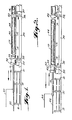
- Figure 1 is a side cutaway view of a testing tool according to the present invention inserted to the far end of a tested pipe segment.
- Figure 2 is a side cutaway view of a testing apparatus according to the present invention with the testing tool inserted to a front end of a tested pipe segment.
- The apparatus and method of the present invention will be described with reference to drawing figures 1 and 2. The
testing tool 10 is comprised of amain body portion 12 which is approximately 12-40 feet in length. The main body portion hashigh pressure seals 14 located on each end thereof. These seals are of the type disclosed in U.S. Patent 3,038,542. The seals used in the packer assembly disclosed in U.S. Patent 3,038,542 have since been developed so as to be capable of withstanding pressures exceeding 25,000 PSI exerted from within the segmented pipe length being tested. -
Main body portion 12 has adrawbar 16 attached to rearward end thereof. This drawbar comprises a smaller diameter tubular length which extends from the main body portion of the testing tool and allows the testing tool to be inserted into a pipe length which substantially exceeds the length of themain body portion 12 of the testing tool. Both themain body portion 12 and thedrawbar 16 are tubular in construction and accommodate therein passages for fluids which pressurize theseals 14 and theannular cavity 44. These internal pressure passages are attached topressure line 20 which in turn is connected to a high pressure fluid pumping apparatus (not shown). - The internal sealing of the pipe segment to the tool can be accomplished by one of three methods depending on the test pressure range being used. If the desired test pressure range is 0-10,000 PSI, a seal pressurizing system known as the "orifice" method is generally employed. To use this method, the body portion is equipped with one or two small orifices (each approximately 1/16 inch across) along its length (not shown). Pressurized fluid is pumped into the internal passage of
main body portion 12 so as to simultaneously pressure charge seals 14 and begin fillingannular cavity 44. When the seals have been sufficiently charged with pressure, the accumulated pressure in the seals forces the pumping fluid to exit even more rapidly through the orifice(s) into the surrounding annular cavity. - The second system of pressurizing the seals and annular cavity is used for test pressure ranges exceeding 10,000 psi. This second method is called the "portsub" system. This sytem includes a check valve along the internal pressure line or
main body portion 12 which pressurizes the seals in the range of 900-1200 psi before allowing fluid to pass through an orifice into the annular cavity. The pressurizing fluid is pumped against this check valve throughout the pressurizing phase. Hence, the pressurizing step takes longer than with the orifice system because of the sustained higher pumping pressures. However, this "portsub" method is more suited to higher pressure testing wherein extremely secure sealing of theseals 14 is more critical. A third method of sealingseals 14 is also used in low pressure pipe testing. This third method is known as the "cup packer" method and involves simply forcing theseals 14 into a pipe segment using liberal coatings of lubricant. This third method is used where the inside diameter of a pipe segment is variable to the extent that an inflatable seal could not fit through narrow portions of the pipe and yet still expand sufficiently to seal other larger portions thereof. - The
testing tool 10 is propelled into and withdrawn frompipe segment 40 by drawingmechanism 22. This drawing mechanism may be of any convenient design which enables the positive pushing or pulling of the testing tool in an out of the pipe segments. A preferable construction of the drawing mechanism is a cog driven chain positioned parallel to the path of the testing tool as it is withdrawn and inserted into pipe segments. - The testing tool rides on tool rack support stands 31. These support stands may be equipped with rollers or other slidable bearing apparatus so as to enable the testing tool to slide in and out of a pipe segment.
-
Pipe segment 40 rests on pipe rack stands 30. These pipe rack stands may be of any suitable configuration which can carry the weight of the pipe, testing tool composite, associated test fluids, and also allow movement of the pipe segment laterally across the rack when testing is completed. Between the forward most and the rearward most pipe rack stands there is positioned a pair ofhydraulic cinches 32.Hydraulic cinches 32 are connected to cinch straps or clamps 33 which wrap around andsecure pipe segment 40 againstpipe rack stand 30. In this manner, the pipe segment is securely fastened and restrained against the pipe rack stand should any failure of the pipe take place during testing. - A trough 23 is positioned directly beneath the pipe segment testing area of the
pipe rack stand 30.Trough 34 enables the retrieval and recycling of the fluid which is used to pressurize the pipe segment during testing. - The
main body portion 12 anddrawbar 16 of the testing tool are preferably covered with a rubber jacket so as to prevent damage to the pipe segments as the testing tool is inserted and withdrawn during a testing procedure. Further, atool guide 42 is placed on the front end of atest pipe segment 40 so as to prevent damage to the front end of a pipe segment upon initial insertion therein of the testing tool. - One reason for the success of the present invention is the reduced pressure area available against the testing tool pressure seals 14 on each end of the
main body member 12. The main body portion of the testing tool is substantially similar in outer diameter to a given pipe segment inside diameter. The difference between the respective outside and inside diameters being made up for by the diameter of theseals 14 mounted on each end of themain body portion 12. In this manner, the area of arespective seal 14 against which fluid pressure acts during a testing operation is only the difference in area between the cross sectional area of a pipe segment and the cross sectional area of the main body portion of the testing tool. Hence, instead of opposing several hundred tons of force as required in the prior art testing methods discussed above, the seals of the present testing tool must resist only a fraction of the pressure withstood by the prior art testing apparatus. As such, the present testing apparatus and method is far safer with regard to catastrophic failure of the testing tool and associated seals than the prior art testing methods. Also, the reduced forces allow for a far more compact and simplified apparatus and procedure. - In operation, a pipe segment is placed in approximate horizontal alignment with the testing tool which is resting on the
tool rack 31 and associated rollers. The pipe segment is wrapped by cinch straps or clamps 33 and securely positioned byhydraulic cinches 32 onpipe rack 30.Tool guide 42 is then placed over the front end of the pipe segment so as to protect the front end against damage from the inserted testing tool. The testing tool is liberally coated with piping dope so as to lubricate the testing tool and ease the insertion thereof into the pipe segment. The testing apparatus may also incorporate other means of easing the insertion thereof into the pipe such as small externally biased wheels mounted along the length of themain body portion 12. - Once the pipe segment is secured in position and prepared for insertion of the testing tool, the
drawing mechanism 22 is activated so as to propeldrawbar 16 and the attached testing tool horizontally into thepipe segment 40. The testing tool is inserted until a front end thereof is proximate to a back end of the pipe segment. Once the testing tool is in this initial position, the tool is securely sealed to the surrounding pipe segment by one of the "orifice", "portsub", or "cup packer" sealing methods previously described. After the seals have been sufficiently sealed to create a fluid tight seal aroundmain body portion 12,pressure line 20 is either initially activated (if using the cup packer method) or continues to pump fluid (if using either of the portsub or orifice methods) throughdrawbar 16 andmain body portion 12 into theannular cavity 44 existing between the outside diameter of the testing tool and the inside diameter ofpipe segment 40. During the annular cavity filling stage, air trapped in theannular cavity 44 can be forced past one of theseals 14 by the pressurized fluid filling the annular cavity. This forced venting process occurs until substantially all of the air trapped inannular cavity 44 is forced to exit from the pipe segment. To assist in allowing the air to exit at a particular end of the pipe segment, the pipe segment may be slightly tipped either forward or rearward so as to allow exiting air to naturally travel to theseal 14 located at the upward end of the pipe segment. To complete the test,pressure line 20 continues to bring the testing pressure up to predetermined level suitable for testing the particular pipe segment in question. - Once the operating personnel are satisfied that a particular pipe segment is sufficiently tested (usually an interval of several seconds to several minutes), the pressure is lowered in
annular cavity 44 and seals 14 are depressurized so as to permit withdrawal of the testing tool from within the pipe segment. If the pipe segment is of sufficient length to require an overlapping testing procedure, the testing procedure is repeated throughout segmented lengths of a pipe segment until, through overlapping tests, the entire pipe length has been pressure tested. Usually, a standard pipe length requires no more than two overlapping tests to complete the pressure testing thereof. - In moving the testing tool along segments of
pipe 40, not all of the fluid contained incavity 44 needs to be released therefrom. In this manner, by displacing a certain portion of the pressure fluid with the testing tool along the segments of the pipe segment, only moderate repumping of fluid into the annular cavity is necessary so as to complete subsequent segment tests. - The advantages of the present apparatus and method are several. The pipe segment does not need to be threaded prior to testing so that the expense of threading defective pipe segments can be avoided. If already threaded, the pipe segment threads are not subjected to wear and/or damage resulting from being threaded and unthreaded several times, over the course of its use, merely for pressure testing procedures. Further, a large bulky apparatus for suitably testing the stronger lengths of pipe is not required. By contrast, the apparatus of the present invention is portable to the extent that a particular onsite location can accommodate a pipe length and the length of testing tool in horizontal alignment so as to perform the testing procedure. In certain instances this may be accommodated even on offshore well drilling platforms.
- While we have described our invention in connection with a specific embodiment thereof, it is to be clearly understood that this is done only by way of example, and not as a limitation to the scope of our invention as set forth and in the appended claims.
Claims (10)
arranging a pipe segment in a substantially horizontal plane,
securing said segment of pipe in said substantially horizontal plane,
inserting a pressure tool having front and back end seals into a first end of said pipe until said front end seal of said testing tool is proximate to a second end of said pipe,
sealing said tool inside said pipe segment at said front end and back end seals of said tool,
pumping fluid into the annular space between said tool and an inner surface of said pipe,
pressurizing said fluid in said annular space to a predetermined pressure,
releasing said fluid pressure and said seals between said pipe and said testing tool,
drawing said tool from said pipe until said first end seal of said tool is proximate said front end of said pipe,
sealing said tool inside said pipe segment at said front and back end seals of said tool,
pumping fluid into the annular space between said tool and an inner surface of said pipe
pressurizing said fluid in said annular space to a predetermined pressure,
releasing said fluid pressure and said seals between said pipe and said tool, and
withdrawing said tool from said pipe segment.
said pressurizing steps include pressures in the range of 2000 to in excess of 25,000 psi.
said pressure tool is liberally coated with lubricant prior to insertion into a pipe segment.
a tool guiding collar is placed around said first end of said pipe prior to insertion therein of said pressure tool.
a tubular body portion having first and second ends and having high pressure seal means proximate to each end of said first body portion for sealing said body portion to an inner surface of a surrounding pipe segment
said first end having draw bar means connected thereto for inserting and extracting said tubular body portion from a pipe segment, and
said drawbar means and said tubular body portion having fluid feed lines located therein for pressurizing said seals and for directing fluid outside of said body portion into an annular cavity between said body portion and an inner surface of a surrounding pipe.
said body portion is coated with elastic jacket means for protecting a pipe segment from damage during testing.
said body portion is of fixed length.
said high pressure seal means are capable of withstanding pressures in the range of 0-10,000 psi.
said high pressure seal means are capable of withstanding pressures in excess of 10,000 psi.
arranging a pipe segment in a substantially horizontal plane,
securing said segment of pipe in said substantially horizontal plane,
inserting a pressure tool having front and back end seals into a first end of said pipe until said front end seal of said testing tool is proximate to a second end of said pipe,
sealing said tool inside said pipe segment at said front end and back end seals of said tool,
pumping fluid into the annular space between said tool and an inner surface of said pipe,
pressurizing said fluid in said annular space to a predetermined pressure,
releasing said fluid pressure and said seals between said pipe and said testing tool,
successively repeating the sealing, pumping, pressurizing, and releasing steps and drawing said tool along said pipe until said first end seal of said tool is proximate said front end of said pipe,
sealing said tool inside said pipe segment at said front and back end seals of said tool,
pumping fluid into the annular space between said tool and an inner surface of said pipe
pressurizing said fluid in said annular space to a predetermined pressure,
releasing said fluid pressure and said seals between said pipe and said tool, and
withdrawing said tool from said pipe segment.
Applications Claiming Priority (2)
| Application Number | Priority Date | Filing Date | Title |
|---|---|---|---|
| US07/185,662 US4852393A (en) | 1988-04-25 | 1988-04-25 | Pipe segment pressure tester and process of use |
| US185662 | 1988-04-25 |
Publications (2)
| Publication Number | Publication Date |
|---|---|
| EP0340060A1 true EP0340060A1 (en) | 1989-11-02 |
| EP0340060B1 EP0340060B1 (en) | 1993-01-13 |
Family
ID=22681936
Family Applications (1)
| Application Number | Title | Priority Date | Filing Date |
|---|---|---|---|
| EP89400940A Expired - Lifetime EP0340060B1 (en) | 1988-04-25 | 1989-04-05 | Pipe segment pressure tester and process of use |
Country Status (5)
| Country | Link |
|---|---|
| US (1) | US4852393A (en) |
| EP (1) | EP0340060B1 (en) |
| JP (1) | JPH0249137A (en) |
| CA (1) | CA1330890C (en) |
| DE (1) | DE68904345T2 (en) |
Families Citing this family (13)
| Publication number | Priority date | Publication date | Assignee | Title |
|---|---|---|---|---|
| US5563336A (en) * | 1995-09-13 | 1996-10-08 | Mallet; Ronald J. | Appparatus for pressure testing of tubulars |
| US7845211B2 (en) * | 2004-03-02 | 2010-12-07 | Car-Ber Investments Inc. | Apparatus and method for forming and testing lengths of pipe |
| US6997044B1 (en) * | 2004-09-20 | 2006-02-14 | The United States Of America As Represented By The Secretary Of The Navy | Test system for a flexible tube |
| FR2882823B1 (en) * | 2005-03-04 | 2007-05-11 | Vallourec Mannesmann Oil Gas F | INSTALLATION AND METHOD FOR MECHANICAL SAMPLE SOLICITATION USING A PACKER |
| RU2387967C2 (en) * | 2005-04-14 | 2010-04-27 | Эксонмобил Апстрим Рисерч Компани | Device for pressure test of pipeline |
| US7628056B2 (en) * | 2006-03-22 | 2009-12-08 | Karl-Heinz Krah Gmbh | Internal pressure testing apparatus and method for pipe |
| CN104315349A (en) * | 2014-10-20 | 2015-01-28 | 成都创源油气技术开发有限公司 | Detection accuracy improvement-based system |
| CN105401934B (en) * | 2015-11-25 | 2018-06-01 | 中国石油天然气股份有限公司 | A Visible Simulated Wellbore Experimental Device |
| CN109060257A (en) * | 2018-07-10 | 2018-12-21 | 湖北金牛管业有限公司 | Water test device is closed between a kind of PE wrapped tube and flared pipe fitting |
| CN108918285B (en) * | 2018-08-30 | 2024-03-19 | 番禺珠江钢管(珠海)有限公司 | A pipe segment crushing device and its test method |
| JP7269767B2 (en) * | 2019-03-25 | 2023-05-09 | 株式会社クボタ | watertight test equipment |
| JP7344818B2 (en) * | 2020-03-16 | 2023-09-14 | 株式会社クボタ | Watertightness test equipment and watertightness test method |
| CN115655899A (en) * | 2022-10-27 | 2023-01-31 | 沪东重机有限公司 | Multi-fluid joint body pressure experiment method |
Citations (6)
| Publication number | Priority date | Publication date | Assignee | Title |
|---|---|---|---|---|
| US3712115A (en) * | 1970-10-09 | 1973-01-23 | Lofaso G | Pipe testing apparatus |
| JPS522592A (en) * | 1975-06-24 | 1977-01-10 | Kawaragi Tadashi | Leakage detecting device of fluid tube |
| US4081990A (en) * | 1976-12-29 | 1978-04-04 | Chatagnier John C | Hydraulic pipe testing apparatus |
| US4152924A (en) * | 1978-07-17 | 1979-05-08 | Mayo John H | Sub-sea equipment test and isolation tool |
| SU728009A1 (en) * | 1978-03-16 | 1980-04-15 | Всесоюзный научно-исследовательский институт разработки и эксплуатации нефтепромысловых труб | Stand for hydraulic testing of tubes |
| WO1984004387A1 (en) * | 1983-04-28 | 1984-11-08 | Charles D Hailey | Apparatus and method for internally testing a plurality of interconnected pipe sections |
Family Cites Families (4)
| Publication number | Priority date | Publication date | Assignee | Title |
|---|---|---|---|---|
| US2481013A (en) * | 1947-03-24 | 1949-09-06 | Henderson Elting | Pipe-joint test plug |
| SU845058A1 (en) * | 1979-08-07 | 1981-07-07 | Харьковский Отдел Всесоюзного Научно- Исследовательского Института Водо-Снабжения,Канализации,Гидротехническихсооружений И Инженерной Гидрогеологии"Водгео" | Apparatus for testing tubes by hydrostatic pressure |
| DE2932280A1 (en) * | 1979-08-09 | 1981-02-26 | Baumann & Burmeister | Tube testing system - uses inserted cylinder forming test chamber between inflated sealing rings and leaving free inner passage |
| US4557139A (en) * | 1984-07-31 | 1985-12-10 | Loomis International Inc. | Leak detection method and apparatus |
-
1988
- 1988-04-25 US US07/185,662 patent/US4852393A/en not_active Expired - Lifetime
-
1989
- 1989-04-05 EP EP89400940A patent/EP0340060B1/en not_active Expired - Lifetime
- 1989-04-05 DE DE8989400940T patent/DE68904345T2/en not_active Expired - Fee Related
- 1989-04-24 CA CA000597601A patent/CA1330890C/en not_active Expired - Lifetime
- 1989-04-24 JP JP1101828A patent/JPH0249137A/en active Pending
Patent Citations (6)
| Publication number | Priority date | Publication date | Assignee | Title |
|---|---|---|---|---|
| US3712115A (en) * | 1970-10-09 | 1973-01-23 | Lofaso G | Pipe testing apparatus |
| JPS522592A (en) * | 1975-06-24 | 1977-01-10 | Kawaragi Tadashi | Leakage detecting device of fluid tube |
| US4081990A (en) * | 1976-12-29 | 1978-04-04 | Chatagnier John C | Hydraulic pipe testing apparatus |
| SU728009A1 (en) * | 1978-03-16 | 1980-04-15 | Всесоюзный научно-исследовательский институт разработки и эксплуатации нефтепромысловых труб | Stand for hydraulic testing of tubes |
| US4152924A (en) * | 1978-07-17 | 1979-05-08 | Mayo John H | Sub-sea equipment test and isolation tool |
| WO1984004387A1 (en) * | 1983-04-28 | 1984-11-08 | Charles D Hailey | Apparatus and method for internally testing a plurality of interconnected pipe sections |
Non-Patent Citations (2)
| Title |
|---|
| PATENT ABSTRACTS OF JAPAN vol. 001, no. 007 (E - 77)<157> 15 March 1977 (1977-03-15) * |
| SOVIET INVENTIONS ILLUSTRATED Week C48, 14 January 1984 Derwent World Patents Index; AN L5375, S02 * |
Also Published As
| Publication number | Publication date |
|---|---|
| EP0340060B1 (en) | 1993-01-13 |
| JPH0249137A (en) | 1990-02-19 |
| DE68904345D1 (en) | 1993-02-25 |
| US4852393A (en) | 1989-08-01 |
| CA1330890C (en) | 1994-07-26 |
| DE68904345T2 (en) | 1993-07-15 |
Similar Documents
| Publication | Publication Date | Title |
|---|---|---|
| US4852393A (en) | Pipe segment pressure tester and process of use | |
| US4858464A (en) | Portable pipe testing apparatus | |
| US3165920A (en) | Tool for testing pipe with water and gas simultaneously | |
| EP0126648B1 (en) | Apparatus for sealing joints and leaks | |
| AU661951B2 (en) | Deployment/retrieval method and apparatus for well tools used with coiled tubing | |
| US7475591B2 (en) | Methods and systems for hydrostatic testing a pipeline | |
| US5984582A (en) | Method of extracting a hollow unit laid in the ground | |
| DE2212330B2 (en) | Device for finding, testing and sealing leaks in pipes | |
| NO317032B1 (en) | Method and equipment for fluid transport using coiled tubing, for use in drill string testing | |
| CN101754822A (en) | Device and method for expanding tubular elements | |
| US4377185A (en) | Hydrotest apparatus | |
| US4458522A (en) | Hydrostatic pipe tester and method | |
| EP0150189A1 (en) | Apparatus and method for internally testing a plurality of interconnected pipe sections | |
| US4733554A (en) | Hydro pressure thread tester | |
| RU2155945C2 (en) | Process testing stop valves | |
| CN113530924A (en) | Detection table of hydraulic equipment and use method thereof | |
| EP1974124B1 (en) | Fluid recovery | |
| US8683848B1 (en) | Oil well tubing pressure testing system and method of use | |
| US4617823A (en) | Hydro pressure thread tester | |
| DE3931340A1 (en) | Pneumatically testing sheath of heavy current cable - by sending natural gas under pressure along certain length between sheath and insulation | |
| GB2267352A (en) | Pressure testing gas-lift wells | |
| JPH0492189A (en) | Pipeline repair method and equipment | |
| RU58217U1 (en) | INSTALLATION FOR HYDRAULIC TESTING OF THREADED OIL SORTMENT PIPES | |
| RU2381468C1 (en) | Installation for crushing test of pipes by external hydraulic pressure | |
| CA1063644A (en) | Pipe couplings |
Legal Events
| Date | Code | Title | Description |
|---|---|---|---|
| PUAI | Public reference made under article 153(3) epc to a published international application that has entered the european phase |
Free format text: ORIGINAL CODE: 0009012 |
|
| AK | Designated contracting states |
Kind code of ref document: A1 Designated state(s): DE FR GB IT NL SE |
|
| 17P | Request for examination filed |
Effective date: 19900409 |
|
| 17Q | First examination report despatched |
Effective date: 19910419 |
|
| GRAA | (expected) grant |
Free format text: ORIGINAL CODE: 0009210 |
|
| AK | Designated contracting states |
Kind code of ref document: B1 Designated state(s): DE FR GB IT NL SE |
|
| PG25 | Lapsed in a contracting state [announced via postgrant information from national office to epo] |
Ref country code: IT Free format text: LAPSE BECAUSE OF FAILURE TO SUBMIT A TRANSLATION OF THE DESCRIPTION OR TO PAY THE FEE WITHIN THE PRE;WARNING: LAPSES OF ITALIAN PATENTS WITH EFFECTIVE DATE BEFORE 2007 MAY HAVE OCCURRED AT ANY TIME BEFORE 2007. THE CORRECT EFFECTIVE DATE MAY BE DIFFERENT FROM THE ONE RECORDED.SCRIBED TIME-LIMIT Effective date: 19930113 Ref country code: NL Effective date: 19930113 Ref country code: SE Effective date: 19930113 |
|
| REF | Corresponds to: |
Ref document number: 68904345 Country of ref document: DE Date of ref document: 19930225 |
|
| EN | Fr: translation not filed | ||
| PG25 | Lapsed in a contracting state [announced via postgrant information from national office to epo] |
Ref country code: FR Effective date: 19930604 |
|
| NLV1 | Nl: lapsed or annulled due to failure to fulfill the requirements of art. 29p and 29m of the patents act | ||
| PLBE | No opposition filed within time limit |
Free format text: ORIGINAL CODE: 0009261 |
|
| STAA | Information on the status of an ep patent application or granted ep patent |
Free format text: STATUS: NO OPPOSITION FILED WITHIN TIME LIMIT |
|
| 26N | No opposition filed | ||
| REG | Reference to a national code |
Ref country code: FR Ref legal event code: ST |
|
| REG | Reference to a national code |
Ref country code: GB Ref legal event code: IF02 |
|
| PGFP | Annual fee paid to national office [announced via postgrant information from national office to epo] |
Ref country code: GB Payment date: 20030402 Year of fee payment: 15 |
|
| PGFP | Annual fee paid to national office [announced via postgrant information from national office to epo] |
Ref country code: DE Payment date: 20030417 Year of fee payment: 15 |
|
| PG25 | Lapsed in a contracting state [announced via postgrant information from national office to epo] |
Ref country code: GB Free format text: LAPSE BECAUSE OF NON-PAYMENT OF DUE FEES Effective date: 20040405 |
|
| PG25 | Lapsed in a contracting state [announced via postgrant information from national office to epo] |
Ref country code: DE Free format text: LAPSE BECAUSE OF NON-PAYMENT OF DUE FEES Effective date: 20041103 |
|
| GBPC | Gb: european patent ceased through non-payment of renewal fee |