EP0339690A2 - Smoking article - Google Patents
Smoking article Download PDFInfo
- Publication number
- EP0339690A2 EP0339690A2 EP89110769A EP89110769A EP0339690A2 EP 0339690 A2 EP0339690 A2 EP 0339690A2 EP 89110769 A EP89110769 A EP 89110769A EP 89110769 A EP89110769 A EP 89110769A EP 0339690 A2 EP0339690 A2 EP 0339690A2
- Authority
- EP
- European Patent Office
- Prior art keywords
- article according
- fuel element
- generating means
- article
- aerosol generating
- Prior art date
- Legal status (The legal status is an assumption and is not a legal conclusion. Google has not performed a legal analysis and makes no representation as to the accuracy of the status listed.)
- Granted
Links
Images


Classifications
-
- A—HUMAN NECESSITIES
- A24—TOBACCO; CIGARS; CIGARETTES; SIMULATED SMOKING DEVICES; SMOKERS' REQUISITES
- A24F—SMOKERS' REQUISITES; MATCH BOXES; SIMULATED SMOKING DEVICES
- A24F40/00—Electrically operated smoking devices; Component parts thereof; Manufacture thereof; Maintenance or testing thereof; Charging means specially adapted therefor
- A24F40/40—Constructional details, e.g. connection of cartridges and battery parts
-
- A—HUMAN NECESSITIES
- A24—TOBACCO; CIGARS; CIGARETTES; SIMULATED SMOKING DEVICES; SMOKERS' REQUISITES
- A24B—MANUFACTURE OR PREPARATION OF TOBACCO FOR SMOKING OR CHEWING; TOBACCO; SNUFF
- A24B15/00—Chemical features or treatment of tobacco; Tobacco substitutes, e.g. in liquid form
- A24B15/10—Chemical features of tobacco products or tobacco substitutes
- A24B15/16—Chemical features of tobacco products or tobacco substitutes of tobacco substitutes
- A24B15/165—Chemical features of tobacco products or tobacco substitutes of tobacco substitutes comprising as heat source a carbon fuel or an oxidized or thermally degraded carbonaceous fuel, e.g. carbohydrates, cellulosic material
-
- A—HUMAN NECESSITIES
- A24—TOBACCO; CIGARS; CIGARETTES; SIMULATED SMOKING DEVICES; SMOKERS' REQUISITES
- A24B—MANUFACTURE OR PREPARATION OF TOBACCO FOR SMOKING OR CHEWING; TOBACCO; SNUFF
- A24B15/00—Chemical features or treatment of tobacco; Tobacco substitutes, e.g. in liquid form
- A24B15/10—Chemical features of tobacco products or tobacco substitutes
- A24B15/16—Chemical features of tobacco products or tobacco substitutes of tobacco substitutes
-
- A—HUMAN NECESSITIES
- A24—TOBACCO; CIGARS; CIGARETTES; SIMULATED SMOKING DEVICES; SMOKERS' REQUISITES
- A24D—CIGARS; CIGARETTES; TOBACCO SMOKE FILTERS; MOUTHPIECES FOR CIGARS OR CIGARETTES; MANUFACTURE OF TOBACCO SMOKE FILTERS OR MOUTHPIECES
- A24D1/00—Cigars; Cigarettes
- A24D1/04—Cigars; Cigarettes with mouthpieces or filter-tips
- A24D1/042—Cigars; Cigarettes with mouthpieces or filter-tips with mouthpieces
-
- A—HUMAN NECESSITIES
- A24—TOBACCO; CIGARS; CIGARETTES; SIMULATED SMOKING DEVICES; SMOKERS' REQUISITES
- A24D—CIGARS; CIGARETTES; TOBACCO SMOKE FILTERS; MOUTHPIECES FOR CIGARS OR CIGARETTES; MANUFACTURE OF TOBACCO SMOKE FILTERS OR MOUTHPIECES
- A24D1/00—Cigars; Cigarettes
- A24D1/18—Selection of materials, other than tobacco, suitable for smoking
-
- A—HUMAN NECESSITIES
- A24—TOBACCO; CIGARS; CIGARETTES; SIMULATED SMOKING DEVICES; SMOKERS' REQUISITES
- A24D—CIGARS; CIGARETTES; TOBACCO SMOKE FILTERS; MOUTHPIECES FOR CIGARS OR CIGARETTES; MANUFACTURE OF TOBACCO SMOKE FILTERS OR MOUTHPIECES
- A24D1/00—Cigars; Cigarettes
- A24D1/22—Cigarettes with integrated combustible heat sources, e.g. with carbonaceous heat sources
-
- A—HUMAN NECESSITIES
- A24—TOBACCO; CIGARS; CIGARETTES; SIMULATED SMOKING DEVICES; SMOKERS' REQUISITES
- A24F—SMOKERS' REQUISITES; MATCH BOXES; SIMULATED SMOKING DEVICES
- A24F42/00—Simulated smoking devices other than electrically operated; Component parts thereof; Manufacture or testing thereof
- A24F42/60—Constructional details
Definitions
- the present invention relates to a smoking article which produces an aerosol that resembles tobacco smoke, and which contains no more than a minimal amount of incomplete combustion or pyrolysis products.
- EP-A-0 117 355 (Hearn et al.), describes a proposed cigarette smoking article having a carbon heat source with an axial passageway and a separate flavor generator.
- the heat source (page 2, line 23 to page 7, line 14) is formed by pyrolyzing a preformed, tube-shaped ligno-cellulosic material of e.g. 90 mm or 65 mm length (see Comparative Example 1 and Example 4, respectively) under specified conditions, followed by at least one additional specified process step.
- the purported flavor generator (page 8, lines 8-27) comprises a substrate material, which may be tobacco, alumina, etc., adjacent the mouth end, which is impregnated with or inherently contains at least one thermally releasable flavorant.
- the flavor generator also may comprise a flavored, foamed core inside the heat source. A conventional filter may be placed after the flavor generator.
- the purported formation of an aerosol during use is described from page 8, line 28 to page 9, line 8.
- a smoking article comprising:
- a smoking article comprising:
- a cigarette type smoking article comprising a fuel element and an inorganic fiber insulating member at least 0.5 mm thick surrounding at least a portion of tne fuel element and a paper overwrap for the insulating member, the article including an aerosol forming material physically separate from the fuel element and arranged to receive heat from the fuel element both during puff and during smolder.
- a cigarette type smoking article comprising a fuel element less than 30 mm in length prior to smoking and an inorganic fiber insulating member at least 0.5 mm thick surrounding at least a portion of the fuel element, the article including an aerosol forming material physically separate from the fuel element and arranged to receive heat from the fuel element both during puff and during smolder.
- a smoking article comprising:
- the present invention relates to a smoking article which is capable of producing substantial quantities of aerosol, both initially and over the useful life of the product, without significant thermal degradation of the aerosol former and without the presence of substantial pyrolysis or incomplete combustion products, and preferably without substantial quantities of sidestream smoke.
- Smoking articles in accordance with the present invention are capable of providing the user with the sensations and benefits of cigarette smoking, without burning tobacco.
- an elongated, cigarette type smoking article which utilizes a combustible fuel element, preferably of a carbonaceous material, in conjunction with a pysically separate aerosol generating means which is in conductive heat exchange relationship with the fuel element.
- a combustible fuel element preferably of a carbonaceous material
- aerosol generating means which is in conductive heat exchange relationship with the fuel element.
- the fuel element Upon lighting, the fuel element generates heat which is used to volatilize the aerosol forming substance or substances in the aerosol generating means. These volatile materials are then drawn toward the mouth end, especially during puffing, and into the user's mouth, akin to the smoke of a conventional cigarette.
- the fuel element is less than about 30 mm in length, more preferably less than 15 mm in length, has a density of at least 0.5 g/cc, and is provided with one or more longitudinal passages.
- the aerosol generating means includes a heat stable substrate including one or more aerosol forming substances.
- the heat exchange relationship between the fuel and the aerosol generator is achieved by providing a heat conducting member, such as a metal foil, which efficiently conducts or transfers heat from the burning fuel element to the aerosol generating means. This heat conducting member preferably contacts the fuel element and the aerosol generating means around at least a portion of their peripheral surfaces.
- At least a part of the fuel element is preferably provided with a peripheral insulating member, such as a jacket of insulating fibers, the jacket being preferably resilient and at least 0.5 mm thick, which reduces radial heat loss and assists in retaining and directing heat from the fuel element toward the aerosol generating means.
- the insulating member preferably overwraps at least part of the fuel element, and advantageously at least part of the aerosol generating means.
- the hot, burning fire cone is always close to the aerosol generating means, which maximizes heat transfer thereto and maximizes the resultant production of aerosol, especially in embodiments which are provided with a heat conducting member.
- the preferred use of a relatively short, low mass substrate or carrier as the aerosol generating means, in close proximity to the short fuel element, also increases aerosol production by minimizing the heat sink effect of the substrate. Because the aerosol forming substance is physically separate from the fuel element, it is exposed to substantially lower temperatures than are present in the burning fire cone, thereby minimizing the possibility of thermal degradation of the aerosol former.
- the especially preferred use of a carbonaceous fuel element which is substantially free of volatile organic material eliminates the presence of substantial pyrolysis or incomplete combustion products and eliminates the generation of substantial sidestream smoke.
- the smoking article of the present invention normally is provided with a mouthend piece including means, such as a longitudinal passage, for delivering the volatile material produced by the aerosol generating means to the user.
- a mouthend piece including means, such as a longitudinal passage, for delivering the volatile material produced by the aerosol generating means to the user.
- the article has the same overall dimensions as a conventional cigarette, and as a result, the mouthend piece and the aerosol delivery means usually extend over more than half the length of the article.
- the fuel element and the aerosol generating means may be produced without a built-in mouthend piece or aerosol delivery means, for use with a separate, disposable or reusable mouthend piece.
- the smoking article of the present invention also may include a charge or plug of tobacco which may be used to add a tobacco flavor to the aerosol.
- the tobacco is placed at the mouth end of the aerosol generating means, or it may be mixed with the carrier for the aerosol forming substance.
- Flavoring agents also may be incorporated into the article to flavor the aerosol delivered to the user.
- Preferred embodiments of the invention are capable of delivering at least 0.6 mg of aerosol, measured as wet total particulate matter, in the first 3 puffs, when smoked under FTC smoking conditions.
- FTC smoking conditions consist of two seconds of puffing (35 ml total volume) separated by 58 seconds of smolder).
- More preferred embodiments of the invention are capable of delivering 1.5 mg or more of aerosol in the first 3 puffs.
- embodiments of the invention are capable of delivering 3 mg or more of aerosol in the first 3 puffs when smoked under FTC smoking conditions.
- preferred embodiments of the invention deliver an average of at least about 0.8 mg of wet total particulate matter per puff for at least about 6 puffs, preferably at least about 10 puffs, under FTC smoking conditions.
- the smoking article of the present invention also is capable of providing an aerosol which is chemically simple, consisting essentially of oxides of carbon, air, water, and the aerosol which carries any desired flavorants or other desired volatile materials, and trace amounts of other materials.
- the aerosol preferably has no significant mutagenic activity according to the Ames test discussed hereinafter.
- the article may be made virtually ashless so that the user does not have to remove any ash during use.
- aerosol is defined to include vapors, gases, particles, and the like, both visible and invisible, and especially those components perceived by the user to be “smoke-like,” generated by action of the heat from the burning fuel element upon substances contained within the aerosol generating means, or elsewhere in the article.
- aerosol also includes volatile flavoring agents and/or pharmacologically or physiologically active agents, irrespective of whether they produce a visible aerosol.
- conductive heat exchange relationship is defined as a physical arrangement of the aerosol generating means and the fuel element whereby heat is transferred by conduction from the burning fuel element to the aerosol generating means substantially throughout the burning period of the fuel element.
- Conductive heat exchange relationships can be achieved by locating the aerosol generating means in contact with the fuel element and in close proximity to the burning portion of the fuel element, and/or by utilizing a conductive member to carry heat from the burning fuel to the aerosol generating means. Preferably both methods of providing conductive heat transfer are used.
- carbonaceous means primarily comprising carbon
- the term "insulating means" applies to all materials which act primarily as insulators. Preferably, these materials do not burn during use, but they may include slow burning carbons and like materials, as well as materials which fuse during use, such as low temperature grades of glass fibers.
- the insulators have a thermal conductivity in g-cal/(sec) (cm2)( o C/cm), of less than about 0.05, preferably less than about 0.02, most preferably less than about 0.005. See, Hackh's Chemical Dictionary , 34 (4th ed., 1969) and Lange's Handbook of Chemistry , 10, 272-274 (11th ed., 1973).
- the invention relates to a smoking article comprising a carbonaceous fuel element, a physically separate areosol generating means including a substrate bearing an aerosol forming material, and a mouthend piece, wherein the fuel element and the substrate being arranged in a conductive heat exchange relationship such that the heat stable substrate receives conductive heat transfer substantially throughout the time of buring of the fuel element.
- the fuel element is less than about 30 mm in length.
- An advantageous embodiment of the invention comprises a combustible fuel element less than about 30 mm in length, and having a density of at least 0.5 g/cc, an aerosol generating means in conductive heat exchange relationship with the fuel element, and means for delivering the aerosol produced by the aerosol generating means to the user.
- a preferred embodiment comprises a fuel element, a physically separate aerosol generating means including an aerosol forming material and an insulating member surrounding at least a portion of the fuel element.
- the fuel element and the aerosol generating means are in a conductive heat exchange relationship.
- Preferred embodiments of the invention are designed such that the article produces wet total particulate matter having no mutagenic activity, as measured by the Ames test.
- the insulating member comprises a fibrous material.
- the insulating member further surrounds at least a portion of the aerosol generating means.
- the fuel element is a carbonaceous material and is less than 20 mm in length.
- the fuel element is less than 15 mm in length.
- a preferred embodiment of the inventive article comprises a heat conducting member which contacts both the fuel element and the aerosol generator means.
- the heat conducting member is metallic. It is then proposed to use as said metallic member a metallic foil which encompasses at least a portion of both the fuel element and the aerosol generator means.
- a metallic member which encloses a substrate bearing the aerosol forming material.
- the metallic member is a metallic rod embedded within at least a portion of both the fuel element and the aerosol generator means.
- the aerosol generating means may be advantageous to have the aerosol generating means at least partially contained within a cavity in the fuel element.
- the aerosol generating means comprises a porous, nonparticulate substrate, having a longitudinal passageway at least partially therethrough.
- Preferred embodiments of the inventive article are designed such that they deliver at least about 0.6 mg of wet total particulate matter in the first three puffs under FTC smoking conditions.
- the article delivers at least about 1.5 mg of wet total particulate matter in the first three puffs under FTC smoking conditions. It is proposed to design the article such that it delivers an average of at least about 0.8 mg per puff of wet total particulate matter under FTC smoking conditions, for at least six puffs.
- the aerosol generating means contains a substrate loaded with from about 35 mg to 85 mg of aerosol former.
- at least about 15 weight percent of the aerosol former is delivered as wet total particulate matter under FTC smoking conditions.
- a preferred embodiment of the inventive article comprises a charge of tobacco located between the mouth end of the fuel element and the mouth end of the article.
- Preferred embodiments of the inventive article are designed such that the fuel element produces substantially no visible sidestream smoke during smolder.
- the fuel element comprises carbon-containing material.
- the length of the fuel element is less than 20 mm and more advantageously less than 15 mm.
- a preferred embodiment of an elongate inventive smoking article comprises a fuel element less than 30 mm in length, a physically separate aerosol generating means including a carrier bearing an aerosol forming material, means for conducting heat from the fuel element to the aerosol generating means, and an insulating member which surrounds at least a portion of the fuel element.
- the heat conducting means comprises a heat conducting member which contacts both the fuel element and the aerosol generating means, and more advantageously the heat conducting member encloses the carrier for the aerosol forming material. It is suggested to use an insulating member which is resilient and at least 0.5 mm thick.
- a fuel element which comprises a carbon-containing material it is preferred to use a fuel element which comprises a carbon-containing material. It is advangeous to use a fuel element which is carbonaceous. In all these cases it is suggested to use a fuel element which is less than 15 mm in length.
- this article should be designed such that it delivers an average of at least 0.8 mg per puff of wet total particulate matter under FTC smoking conditions, for at least six puffs.
- the embodiment of the invention illustrated in Figure 1 which preferably has the diameter of a conventional cigarette, includes a short, combustible carbonaceous fuel element 10, an abutting aerosol generating means 12, and a foil lined paper tube 14, which forms the mouthend piece 15 of the article.
- fuel element 10 is a "blowpipe" charcoal, i.e. carbonized wood, which is provided with five longitudinally extending holes 16. See Figure 1A.
- Aerosol generating means 12 includes a plurality of glass beads 20 coated with an aerosol forming substance or substances, such as glycerin.
- the glass beads are held in place by a porous disc 22, which may be made of cellulose acetate. This disc may be provided with a series of peripheral grooves 24 which provide passages between the disc and the foil lined tube 14.
- the foil lined paper tube 14 which forms the mouthend piece of the article, surrounds aerosol generating means 12 and the rear, non-lighting end of fuel element 10.
- the tube also forms an aerosol delivery passage 26 between the aerosol generating means 12 and mouth end 15 of the article.
- foil lined tube 14 which couples the nonlighting end of fuel 10 to aerosol generator 12, also increases heat transfer to the aerosol generator.
- the foil also helps to extinguish the fire cone. When only a small amount of the unburned fuel remains, heat loss through the foil acts as a heat sink which helps to extinguish the fire cone.
- the foil used in this article is typically an aluminum foil of 0.35 mils (0.0089 mm) in thickness, but the thickness and/or the type of metal employed may be varied to achieve any desired degree of heat transfer.
- Other types of heat conducting members such as Grafoil, available from Union Carbide, also may be employed.
- the article illustrated in Figure 1 also includes an optional mass or plug of tobacco 28 to contribute flavor to the aerosol.
- This tobacco charge 28 may be placed at the mouth end of disc 22, as shown in Figure 1, or it may be placed between glass beads 20 and disc 22. It also may be placed in passage 26 at a location spaced from aerosol generator 12.
- the short fuel element 10 is a pressed carbon rod or plug, about 20 mm long, which is provided with an axial hole 16.
- the fuel may be formed from carbonized fibers and preferably also provided with an axial passageway corresponding to hole 16.
- aerosol generating means 12 includes a thermally stable conductive carbonaceous substrate 30, such as a plug of porous carbon, which is impregnated with an aerosol forming substance or substances.
- This substrate may be provided with an optional axial passageway 32, as is shown in Figure 2.
- This embodiment also includes a mass of tobacco 28 which is preferably placed at the mouth end of substrate 30.
- this article also includes an optional high porosity cellulose acetate filter 34, which may be provided with peripheral grooves 36 to provide passages for the aerosol forming substance between filter 34 and foil tube 14.
- an optional high porosity cellulose acetate filter 34 may be provided with peripheral grooves 36 to provide passages for the aerosol forming substance between filter 34 and foil tube 14.
- the lighting end 11 of the fuel element may be tapered to improve lightability.
- the embodiment of the invention illustrated in Figure 3 includes a short combustible carbonaceous fuel element 10, connected to aerosol generating means 12 by a heat conductive rod 99 and by a foil lined paper tube 14, which also leads to the mouth end 15 of the article.
- fuel element 10 may be blowpipe charcoal or a pressed or extruded carbon rod or plug or other carbonaceous fuel source.
- Aerosol generating means 12 includes a thermally stable carbonaceous substrate 30, such as a plug of porous carbon, which is impregnated with an aerosol forming substance or substances.
- This embodiment includes a void space 97 between the fuel element 10 and the substrate 30.
- the portion of the foil lined tube 14 surrounding this void space includes a plurality of peripheral holes 100 which permit sufficient air to enter the void space to provide appropriate pressure drop.
- the heat conducting means includes a conductive rod 99 and the foil lined tube 14.
- the rod 99 preferably formed of aluminum, has at least one, preferably from 2 to 5, peripheral grooves 96 therein, to allow air passage through the substrate.
- the article of Figure 3 has the advantage that the air introduced into the void space 97 contains less carbon oxidation products because it is not drawn through the burning fuel.
- the embodiment illustrated in Figure 4 includes a fibrous carbon fuel element 10, such as carbonized cotton or rayon.
- the fuel element includes a single axial hole 16.
- the substrate 38 of the aerosol generator is a granular, thermally stable carbon.
- a mass of tobacco 28 is located immediately behind the substrate.
- This article is provided with a cellulose acetate tube 40, in place of the foil lined tube of previous embodiments.
- This tube 40 includes an annular section 42 of cellulose acetate tow surrounding an optional plastic, e.g., polypropylene tube 44.
- the entire length of the article is wrapped in cigarette-type paper 46.
- a cork or white ink coating 48 may be used on the mouth end to simulate tipping.
- a foil strip 50 is located on the inside of the paper, toward the fuel end of the article. This strip preferably extends from the rear portion of the fuel element to the mouth end of the tobacco charge 28. It may be integral with the paper or it may be a separate piece applied before the paper overwrap.
- the aerosol generating means 12 is formed by an aluminum macrocapsule 52 which is filled with a granular substrate or, as shown in the drawing, a mixture of a granular substrate 54, and tobacco 56.
- the macrocapsule 52 is crimped at its ends 58, 60 to enclose the material and to inhibit migration of the aerosol former.
- the crimped end 58, at the fuel end preferably abuts the rear end of the fuel element to provide for conductive heat transfer.
- a void space 62 formed by end 58 also helps to inhibit migration of the aerosol former to the fuel.
- Longitudinal passageways 59 and 61 are provided to permit the passage of air and the aerosol forming substance.
- Macrocapsule 52 and fuel element 10 may be united by a conventional cigarette paper 47, as illustrated in the drawing, by a perforated ceramic paper, or a foil strip. If cigarette paper is used, a strip 64 near the rear end of the fuel should be printed or treated with sodium silicate or other known materials which cause the paper to extinguish. The entire length of the article is overwrapped with conventional cigarette paper 46.
- Figure 6 illustrates another embodiment having a pressed carbon fuel plug 10.
- the fuel element has a tapered lighting end 11 for easier lighting and a tapered rear end 9 for easy fitting into a tubular foil wrapper 66.
- Abutting the rear end of the fuel element is an aluminum disc 68 with a center hole 70.
- a second, optional aluminum disc 72 with hole 74 is located at the mouth end of the aerosol generator 12.
- In between is a zone 76 of a particulate substrate and a zone 78 of tobacco.
- the foil wrapper 66 in which the fuel element is mounted extends back beyond the second aluminum disc 72.
- This embodiment also includes a hollow cellulose acetate rod 42 with an internal polypropylene tube 44, and a cellulose acetate filter plug 45. The entire length of the article is preferably wrapped with cigarette paper 46.
- the embodiment shown in Figure 7 illustrates the use of a substrate 80 embedded within a large cavity 82 in fuel element 10.
- the fuel element preferably is formed from an extruded carbon, and the substrate 80 usually is a relatively rigid, porous material.
- the entire length of the article is wrapped with conventional cigarette paper 46.
- This embodiment may also include a foil strip 84 to couple fuel element 10 to the cellulose acetate tube 40 and to help extinguish the fuel.
- inventions shown in Figures 8 and 9 include a nonburning insulating jacket 86 around fuel element 10 to insulate and concentrate the heat in the fuel element. These embodiments also help to reduce any fire causing potential of the burning fire cone.
- both fuel element 10 and substrate 30 are located within an annular jacket or tube 86 of insulating fibers, such as ceramic (e.g., glass) fibers. Nonburning carbon or graphite fibers may be used in place of ceramic fibers.
- Fuel element 10 is preferably an extruded carbon plug having a hole 16. In the illustrated embodiment, the lighting end 11 extends slightly beyond the edge of jacket 86 for ease of lighting.
- Substrate 30 is a solid porous carbon material, although other types of substrates may be used. The substrate and the rear portion of the fuel element are surrounded by a piece of aluminum foil 87.
- this jacketed fuel/substrate unit is coupled to a mouthend piece, such as the elongated cellulose acetate tube 40 shown in the drawing, with an overwrap of conventional cigarette paper 46.
- the jacket 86 extends to the mouth end of substrate 30, but may replace cellulose acetate rod 42.
- an aluminum macrocapsule 52 of the type shown in Figure 5 is used to enclose a granular substrate 54 and tobacco 56.
- This macrocapsule is preferably positioned entirely within the insulator jacket 86.
- the lighting end 11 of fuel element 10 does not protrude beyond the forward end of jacket 86.
- the macrocapsule and the rear portion of the fuel element are surrounded by a piece of aluminum foil in a manner similar to that shown in Figure 8.
- the aluminum foil 52 which surrounds the substrate is only crimped at the mouth end.
- the rear end of the fuel element may be inserted into one end of the foil and a polypropylene tube may be fitted over or placed in abutment with the mouth end of the foil.
- the entire assembly is overwrapped with fiberglass to a diameter of a conventional cigarette.
- the fuel element Upon lighting any of the aforesaid embodiments, the fuel element burns, generating the heat used to volatilize the aerosol forming substance or substances present in the aerosol generating means. These volatile materials are then drawn toward the mouthend, especially during puffing, and into the user's mouth, akin to the smoke of a conventional cigarette.
- the hot, burning fire cone is always close to the aerosol generating body, which maximizes heat transfer to the aerosol generating means, and resultant production of aerosol, especially when the preferred heat conducting member is used.
- the preferred insulating member tends to confine, direct, and concentrate the heat toward the central core of the article, thereby increasing the heat transferred to the aerosol forming substance.
- the aerosol forming substance is physically separate from the fuel element, it is exposed to substantially lower temperatures than are present in the burning fire cone. This minimizes the possibility of thermal degradation of the aerosol former. This also results in aerosol production during puffing, but little or no aerosol production during smolder.
- the use of the preferred carbonaceous fuel elements and a physically separate aerosol generating means eliminates the presence of substantial pyrolysis or incomplete combustion products and avoids the production of substantial sidestream smoke.
- the fuel element Because of the small size and burning characteristics of the preferred carbonaceous fuel element employed in the present invention, the fuel element usually begins burning over substantially all of its exposed length within a few puffs. Thus, the portion of the fuel element adjacent to the aerosol generating means becomes hot quickly, which significantly increases heat transfer to the aerosol generating means, especially during the early and middle puffs. Because the preferred fuel element is short, there is never a long section of nonburning fuel to act as a heat sink, as was common in previous thermal aerosol articles. Heat transfer, and therefor aerosol delivery, also is enhanced by the use of holes through the fuel, which draw hot air to the aerosol generator, especially during puffing.
- the short carbonaceous fuel element, heat conducting member, insulating means, and passages in the fuel cooperate with the aerosol generator to provide a system which is capable of producing substantial quantities of aerosol, on virtually every puff.
- the aerosol generating means is maintained at a relatively high temperature between puffs, and that the additional heat delivered during puffs, which is significantly increased by the hole or holes in the fuel element, is primarily utilized to vaporize the aerosol forming substance.
- This increased heat transfer makes more efficient use of the available fuel energy, reduces the amount of fuel needed, and helps deliver early aerosol.
- the conductive heat transfer utilized in the present invention is believed to reduce the carbon fuel combustion temperature which, it is further believed, reduces the CO/CO2 ratio in the combustion products produced by the fuel. See, e.g., G. Hagg, General Inorganic Chemistry , at p. 592 (John Wiley & Sons, 1969).
- the appropriate selection of the fuel element, the insulating jacket, the paper overwrap, and the heat conducting means it is possible to control the burn properties of the fuel source. This provides opportunities for control of heat transfer to the aerosol generator, which in turn, alters the number of puffs and/or the amount of aerosol delivered to the user.
- the combustible fuel elements which may be employed in practicing the invention are less than about 30 mm long.
- the fuel element is about 20 mm or less, preferably about 15 mm or less in length.
- the diameter of the fuel element is between about 3 and 8 mm, preferably about 4 to 5 mm.
- the density of the fuel elements employed herein has ranged from about 0.5 g/cc to about 1.5 g/cc.
- the density is greater than 0.7 g/cc., more preferably greater than 0.8 g/cc.
- the fuel is provided with one or more longitudinally extending holes, such as holes 11 in Figures 1 through 5. These holes provide porosity and increase early heat transfer to the substrate by increasing the amount of hot gases which reach the substrate.
- the preferred fuel elements employed herein are primarily formed of a carbonaceous material.
- Carbonaceous fuel elements are preferably from about 5 to 15 mm, more preferably, from about 8 to 12 mm in length. Carbonaceous fuel elements having these characteristics are sufficient to provide fuel for at least about 7 to 10 puffs, the normal number of puffs generally obtained by smoking a conventional cigarette under FTC conditions.
- the carbon content of such a fuel element is at least 60 - 70%, most preferably at least about 80% or more by weight. Excellent results have been achieved with fuel elements having a carbon content of above above about 85% by weight. High carbon content fuels are preferred because they produce minimal pyrolysis and incomplete combustion products, little or no visible sidestream smoke, and minimal ash and have high heat capacity. However, lower carbon content fuel elements, e.g., about 50 - 65 weight percent, are within the scope of this invention, especially where a nonburning inert filler is used.
- other fuel materials may be employed, such as tobacco, tobacco substitutes and the like, provided that they they generate and conduct sufficient heat to the aerosol generating means to produce the desired level of aerosol from the aerosol forming material, as discussed above.
- the density of the fuel used should be above about 0.5g/cc., preferably above about 0.7 g/cc., which is higher than the densities normally used in conventional smoking articles.
- it is much preferred to include carbon in the fuel preferably in amounts of at least about 20 - 40% by weight, more preferably at least about 50% by weight, and most preferably at least about 65 -70% by weight, the balance being being the other fuel components, including any binder, burn modifiers, moisture, etc.
- the carbonaceous materials used in or as the preferred fuel may be derived from virtually any of the numerous carbon sources known to those skilled in the art.
- the carbonaceous material is obtained by the pyrolysis or carbonization of cellulosic materials, such as wood, cotton, rayon, tobacco, coconut, paper, and the like, although carbonaceous materials from other sources may be used.
- the carbonaceous fuel element should be capable of being ignited by a conventional cigarette lighter without the use of an oxidizing agent.
- Burning characteristics of this type may generally be obtained from a cellulosic material which has been pyrolyzed at temperatures between about 400 o C to about 1000 o C, preferably between about 500 o C to about 950 o C, in an inert atmosphere or under a vacuum.
- the pyrolysis time is not believed to be critical, as long as the temperature at the center of the pyrolyzed mass has reached the aforesaid temperature range for at least a few minutes.
- a slow pyrolysis employing gradually increasing temperatures over several hours is believed to produce a more uniform material with a higher carbon yield.
- carbonaceous fuel elements which require the addition of an oxidizing agent to render them ignitable by a cigarette lighter are within the scope of this invention, as are carbonaceous materials which require the use of a glow retardant or other type of combustion modifying agent.
- combustion modifying agents are disclosed in many patents and publications and are known to those of ordinary skill in the art.
- the most preferred carbonaceous fuel elements used in practicing the invention are substantially free of volatile organic material.
- the fuel element is not purposely impregnated or mixed with substantial amounts of volatile organic materials, such as volatile aerosol forming or flavoring agents, which could degrade in the burning fuel.
- volatile organic materials such as volatile aerosol forming or flavoring agents, which could degrade in the burning fuel.
- small amounts of water, which are naturally adsorbed by the fuel may be present therein.
- small amounts of aerosol forming substances may migrate from the aerosol generating means and thus may also be present in the fuel element.
- a preferred carbonaceous fuel element is a pressed or extruded carbon mass prepared from carbon and a binder, by conventional pressure forming or extrusion techniques.
- a preferred activated carbon for such a fuel element is PCB-G, and a preferred non-activated carbon is PXC, both available from Calgon Carbon Corporation, Pittsburgh, PA.
- Other preferred carbons for pressure forming and/or extrusion are prepared from pyrolyzed cotton or pyrolyzed papers.
- binders which may be used in preparing such a fuel element are well known in the art.
- a preferred binder is sodium carboxymethylcellulose (SCMC), which may be used alone, which is preferred, or in conjunction with materials such as sodium chloride, vermiculite, bentonite, calcium carbonate, and the like.
- SCMC sodium carboxymethylcellulose
- Other useful binders include gums, such as guar gum, and other cellulose derivatives, such as methylcellulose and carboxymethylcellulose (CMC).
- binder concentrations can be utilized.
- the amount of binder is limited to minimize contribution of the binder to undesirable combustion products.
- sufficient binder must be included to hold the fuel element together during manufacture and use. The amount used will thus depend on the cohesiveness of the carbon in the fuel element.
- the aforesaid fuel elements may be pyrolyzed after formation, for example, to about 650 o C for two hours, to convert the binder to carbon thereby forming a virtually 100% carbon fuel element.
- the fuel elements employed in the present invention also may contain one or more additives to improve burning, such as up to about 5 weight percent sodium chloride to improve smoldering characteristics and as a glow retardant. Also, up to about 5, preferably 1 to 2, weight percent of potassium carbonate may be included to improve lightability. Additives to improve physical characteristics, such as clays like kaolins, serpentines, attapulgites, and the like also may be used.
- Another carbonaceous fuel element is a carbon fiber fuel, which may be prepared by carbonizing a fibrous precursor, such as cotton, rayon, paper, polyacrylonitile, and the like. Generally, pyrolysis at from about 650 o C to 1000 o , preferably at about 950 o , for about 30 minutes, in an inert atmosphere or vacuum, is sufficient to produce a suitable carbon fiber with good burning characteristics. Combustion modifying additives also may be added to these fibrous fuels.
- the aerosol generating means used in practicing the invention is physically separate from the fuel element.
- physically separate it is meant that the substrate, container or chamber which contains the aerosol forming materials is not mixed with, or a part of, the burning fuel element.
- this arrangement helps reduce or eliminate thermal degradation of the aerosol forming substance and the presence of sidestream smoke.
- the aerosol generating means is in a conductive heat exchange relationship with the fuel element, and preferably abuts or is adjacent to the fuel element.
- the aerosol generating means includes one or more thermally stable materials which carry one or more aerosol forming substances.
- a thermally stable material is one capable of withstanding the high temperatures, e.g., 400 o C - 600 o C, which exist near the fuel without decomposition or burning. The use of such material is believed to help maintain the simple "smoke" chemistry of the aerosol, as evidenced by the lack of Ames activity in the preferred embodiments.
- other aerosol generating means such as heat rupturable microcapsules, or solid aerosol forming substances, are within the scope of the invention, provided they are capable of releasing sufficient aerosol forming vapors to satisfactorily resemble tobacco smoke.
- Thermally stable materials which may be used as a substrate or carrier for the aerosol forming substance are well known to those skilled in the art.
- Useful substrates should be porous and must be capable of retaining an aerosol forming compound when not in use and capable of releasing a potential aerosol forming vapor upon heating by the fuel element.
- thermally stable materials include thermally stable adsorbent carbons, such as porous grade carbons, graphite, activated, or nonactivated carbons, and the like.
- suitable materials include inorganic solids such as ceramics, glass, alumina, vermiculite, clays such as bentonite, and the like.
- the currently preferred substrate materials are carbon felts, fibers, and mats, activated carbons, and porous carbons such as PC-25 and PG-60 available from Union Carbide, as well as SGL carbon available from Calgon.
- composition and configuration thereof may generally be selected from particulate, fibrous, porous blocks, solid blocks with one or more axially extending passageways therethrough, and the like.
- Substrates, especially particulates may be placed within a container, preferably formed from a metallic foil.
- the aerosol generating means used in the invention is usually located no more than about 60 mm, preferably no more than 30 mm, most preferably no more than 15 mm from the lighting end of the fuel element.
- the aerosol generator may vary in length from about 2 mm to about 60 mm, preferably from about 5 mm to 40 mm, and most preferably from about 20 mm to 35 mm. If a non-particulate substrate is used, it may be provided with one or more holes, to increase the surface area of the substrate, and to increase air flow and heat transfer.
- the aerosol forming substance or substances used in the invention must be capable of forming an aerosol at the temperatures present in the aerosol generating means when heated by the burning fuel element.
- Such substances preferably will be composed of carbon, hydrogen and oxygen, but they may include other materials.
- the aerosol forming substances can be in solid, semisolid, or liquid form.
- the boiling point of the substance and/or the mixture of substances can range up to about 500 o C.
- Substances having these characteristics include polyhydric alcohols, such as glycerin and propylene glycol, as well as aliphatic esters of mono-, di-, or poly-carboxylic acids, such as methyl stearate, dodecandioate, dimethyl tetradodecandioate, and others.
- the aerosol forming substances will include a mixture of a high boiling, low vapor pressure substance and a low boiling, high vapor pressure substance.
- the low boiling substance will provide most of the initial aerosol, while, when the temperature in the aerosol generator increases, the high boiling substance will provide most of the aerosol.
- the preferred aerosol forming substances are polyhydric alcohols, or mixtures of polyhydric alcohols.
- Especially preferred aerosol formers are selected from glycerin, propylene glycol, triethylene glycol, or mixtures thereof.
- the aerosol forming substance may be dispersed on or within the aerosol generating means in a concentration sufficient to permeate or coat the substrate, carrier, or container.
- the aerosol forming substance may be applied full strength or in a dilute solution by dipping, spraying, vapor deposition, or similar techniques.
- Solid aerosol forming components may be admixed with the substrate and distributed evenly throughout prior to formation.
- the amount of liquid aerosol forming substances may generally vary from about 20 mg to about 120 mg, preferably from about 35 mg to about 85 mg, and most preferably from about 45 mg to about 65 mg.
- the aerosol former carried on the aerosol generating means should be delivered to the user as WTPM.
- WTPM weight percent
- the aerosol former carried on the aerosol generating means is delivered to the user as WTPM.
- the aerosol generating means also may include one or more volatile flavoring agents, such as menthol, vanillin, artificial coffee, tobacco extracts, nicotine, caffeine, liquors, and other agents which impart flavor to the aerosol. It also may include any other desirable volatile solid or liquid materials.
- volatile flavoring agents such as menthol, vanillin, artificial coffee, tobacco extracts, nicotine, caffeine, liquors, and other agents which impart flavor to the aerosol. It also may include any other desirable volatile solid or liquid materials.
- the smoking article of the present invention also may include a charge or plug of tobacco which may be used to add a tobacco flavor to the aerosol.
- the tobacco is placed at the mouth end of the aerosol generating means, or it may be mixed with the carrier for the aerosol forming substance.
- Flavoring agents also may be incorporated into the article to flavor the aerosol delivered to the user.
- these optional agents may be placed between the aerosol generating means and the mouthend, such as in a separate substrate or chamber in the passage which leads from the aerosol generating means to the mouthend, or in the optional tobacco charge.
- these volatile agents may be used in lieu of part, or all, of the aerosol forming substance, so that the article delivers a nonaerosol flavor or other material to the user.
- Articles of the type disclosed herein may be used or may be modified for use as drug delivery articles, for delivery of volatile pharmacologically or physiologically active materials such as ephedrine, metaproterenol, terbutaline or the like.
- the heat conducting member preferably employed in practicing this invention is typically a metallic foil, such as aluminum foil, varying in thickness from less than about 0.01 mm to about 0.1 mm, or more.
- the thickness and/or the type of conducting material may be varied to achieve virtually any desired degree of heat transfer.
- the heat conducting member preferably contacts or overlaps a portion of the fuel element and the aerosol generating means, and may form the container which encloses the aerosol forming substance.
- Insulating members which may be used in accordance with the present invention generally comprise inorganic or organic fibers such as those made out of glass, alumina, silica, vitreous materials, mineral wool, carbons, silicons, boron, organic polymers, cellulosics, and the like, including mixtures of these materials.
- Nonfibrous insulating materials such as silica aerogel, pearlite, glass, and the like, formed in mats, strips or other shapes, may also be used.
- Preferred insulating members are resilient, to help simulate the feel of a conventional cigarette. These materials act primarily as an insulating jacket, retaining and directing a significant portion of the heat formed by the burning fuel element to the aerosol generating means. Because the insulating jacket becomes hot adjacent to the burning fuel element, to a limited extent, it also may conduct heat toward the aerosol generating means.
- insulating materials include ceramic fibers, such as glass fibers.
- Two especially preferred glass fibers are available from the Manning Paper Company of Troy, New York, under the designations, Manniglas 1000 and Manniglas 1200.
- the insulating fiber is wrapped over at least a portion of the fuel element and any other desired portion of the article, to a final diameter of from about 7 to 8 mm.
- the preferred thickness of the insulating layer is from about 0.5 mm to 2.5 mm, preferably, from about 1 mm to 2 mm.
- glass fiber materials having a low softening point e.g., below about 650 o C, are preferred.
- barrier means at the mouth end of the article.
- One such barrier means comprises an annular member of high density cellulose acetate tow which abutts the fibrous insulating means and which is sealed, preferably at the mouth end, with, for example, glue, to block air flow through the tow.
- the fuel/aerosol generating means combination will be attached to a mouthend piece, such as a foil lined paper or cellulose acetate/plastic tubes illustrated in the figures, although a mouthend piece may be provided separately, e.g., in the form of a cigarette holder.
- a mouthend piece such as a foil lined paper or cellulose acetate/plastic tubes illustrated in the figures, although a mouthend piece may be provided separately, e.g., in the form of a cigarette holder.
- This element of the article provides the passageway which channels the vaporized aerosol forming substance into the mouth of the user. Due to its length, preferably about 50 to 60 mm or more, it also keeps the hot fire cone away from the mouth and fingers of the user.
- Suitable mouthend pieces should be inert with respect to the aerosol forming substances, should have a water or liquid proof inner layer, should offer minimum aerosol loss by condensation or filtration, and should be capable of withstanding the temperature at the interface with the other elements of the article.
- Preferred mouthend pieces include the foil lined tube of Figures 1 - 3 and the cellulose-acetate tube employed in the embodiments of Figures 4 - 9. Other suitable mouthend pieces will be apparent to those of ordinary skill in the art.
- the mouthend pieces of the invention may include an optional "filter” tip, which is used to give the article the appearance of the conventional filtered cigarette.
- filters include low density cellulose acetate filters and hollow or baffled plastic filters, such as those made of polypropylene.
- the entire length of article or any portion thereof may be overwrapped with cigarette paper.
- the aerosol produced by the preferred articles of the present invention is chemically simple, consisting essentially of air, oxides of carbon, the aerosol which carries any desired flavorants or other desired volatile materials, water, and trace amounts of other materials.
- the wet total particulate matter (WTPM) produced by the preferred articles of this invention has no mutagenic activity as measured by the Ames test, i.e., there is no significant dose response relationship between the WTPM of the present invention and the number of revertants occurring in standard test microorganisms exposed to such products. According to the proponents of the Ames test, a significant dose dependent response indicates the presence of mutagenic materials in the products tested. See Ames et al ., Mut . Res. , 31:347-364 (1975); Nagas et al ., Mut . Res. , 42:335 (1977).
- a further benefit from the preferred embodiments of the present invention is the relative lack of ash produced during use in comparison to ash from a conventional cigarette.
- the preferred carbon fuel source As the preferred carbon fuel source is burned, it is essentially converted to oxides of carbon, with relatively little ash generation, and thus there is no need to dispose of ashes while using the article.
- the smoking article of the present invention will be further illustrated with reference to the following examples which aid in the understanding of the present invention, but which are not to be construed as limitations thereof. All percentages reported herein, unless otherwise specified, are percent by weight. All temperatures are expressed in degrees Celsius and are uncorrected. In all instances, the smoking articles have a diameter of about 7 to 8 mm, the diameter of a conventional cigarette.
- a smoking article was constructed in accordance with the embodiment of Figure 1.
- the fuel element was a 25 mm long piece of blow pipe charcoal, with five 0.040 in. (1.02 mm) longitudinal passageways made with a number 60 drill bit.
- the charcoal weighed 0.375 g.
- the fuel element was wrapped with conventional treated cigarette paper.
- the substrate was 500 mg of glass beads (0.64 in. [1.63 mm] average diameter) having two drops, approximately 50 mg, of glycerol coated on their surface. When packed into the tube, this substrate was about 6.5 mm long.
- the foil lined tube consisted of a 0.35 mil (0.0089 mm) layer of aluminum foil inside a 4.25 mil (0.108 mm) layer of white spirally wound paper. This tube surrounded the rear 5 mm of the fuel element.
- a short (8 mm) piece of cellulose acetate with four grooves around the periphery was used to hold the glass beads against the fuel source.
- An additional grooved cellulose acetate filter piece of 8 mm length was inserted into the mouth end of the tube to give the appearance of a conventional cigarette.
- the overall length of the article was about 70 mm.
- Models of this type delivered considerable aerosol on the lighting puff, reduced amounts of aerosol on puffs 2 and 3, and good delivery of aerosol on puffs 4 through 9.
- Models of this type generally yielded about 5-7 mg of wet total particulate matter (WTPM) when machine smoked under FTC smoking procedures of a 35 ml puff volume, a two second puff duration, and a 60 second puff frequency.
- WTPM wet total particulate matter
- Four smoking articles were constructed with 10 mm long pressed carbon fuel elements and glass bead substrates.
- the fuel elements were formed from 90% PCB-G and 10% SCMC, at about 5000 pounds (2273 kg) of applied load with the tapered lighting end illustrated in Figure 2A.
- a single 0.040 in (1.02 mm) hole was formed down the center of each element.
- Three of the four fuel sources were wrapped with 8 mm wide strips of conventional cigarette paper. The fuel elements were inserted about 2 mm into 70 mm long sections of the foil lined tube described in Example 1.
- Example 2A Three smoking articles similar to those described in Example 2A were constructed with 20 mm long blowpipe charcoal fuel elements of the type described in Example 1. These articles were machine smoked under FTC smoking conditions, and the WTPM was collected on a series of Cambridge pads. The results of these tests are reported in Table II. TABLE II WTPM (mg)/Puffs Glass Beads (wt) Aerosol Former (wt) 1-3 4-6 7-9 10-12 Total E 402.4 mg 60.6 mg 0.1 5.4 6.2 0.6 12.3 F* 404.7 mg 63.1 mg 0.5 0.9 2.2 3.1 7.0 G 500.0 mg 50.0 mg 0.3 2.9 3.0 0 6.2 *The fuel rod in this model was not wrapped with cigarette paper.
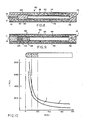
- FIG. 2 Four smoking articles were constructed as shown in Figure 2 with a 10 mm pressed carbon fuel element having the tapered lighting end illustrated in Figure 2A.
- the fuel element was made from 90% PCB-G carbon and 10% SCMC, at about 5000 pounds (2273 kg) of applied load.
- a 0.040 in. (1.02 mm) hole was drilled down the center of the element.
- the substrate for the aerosol former was cut and machined to shape from PC-25, a porous carbon sold by Union Carbide Corporation, Danbury, CT.
- the substrate in each article was about 2.5 mm long, and about 8 mm in diameter. It was loaded with an average of about 27 mg of a 1:1 propylene glycol-glycerol mixture.
- the foil lined tube mouthend piece enclosed the rear 2 mm of the fuel element and the substrate.
- a plug of Burley tobacco, about 100 mg was placed against the mouth end of the substrate.
- a short, about 5-9 mm, baffled polypropylene filter piece was placed in the mouth end of the foil lined tube.
- a 32 mm length of a cellulose acetate filter with a hollow polypropylene tube in the core was placed between the tobacco and the filter piece.
- the overall length of each article was about 78 mm.
- Example 3A Six additional articles were constructed substantially as in Example 3A, but the substrate length was increased to 5 mm, and a 0.040 in (1.02 mm) hole was drilled through the substrate. In addition, these articles did not have a cellulose acetate/polypropylene tube. About 42 mg of the propylene glycol-glycerol mixture was applied to the substrate. In addition, two plugs of Burley tobacco, about 100-150 mg each, were used. The first was placed against the mouth end of the substrate, and the second one was placed against the filter piece.
- Example 3A Four additional articles were constructed substantially as in Example 3A, except that an approximately 100 mg plug of flue-cured tobacco containing about six percent by weight of diammonium monohydrogen phosphate was used in lieu of the plug of Burley tobacco.
- the smoking articles from Examples 3A-C were tested using the standard Ames Test. See Ames, et al ., Mut . Res ., 31:347-364 (1975), as modified by Nagas et al ., Mut . Res ., 42:335 (1977), and 113:173-215 (1983).
- the samples 3A and C were "smoked" on a conventional cigarette smoking machine using the conditions of a 35 ml puff volume, a two second puff duration, and a 30 second puff frequency, for ten puffs.
- the smoking articles of Example 3B were smoked in the same manner except that a 60 second puff frequency was used. Only one filter pad was used for each group of articles. This afforded the following wet total particulate matter (WTPM) for the indicated groups of articles:
- the filter pad for each of the above examples containing the collected WTPM was shaken for 30 minutes in DMSO to dissolve the WTPM. Each sample was then diluted to a concentration of 1 mg/ml and used "as is" in the Ames assay.
- 1 mg/ml concentrations of WTPM were admixed with the S-9 activating system, plus the standard Ames bacterial cells, and incubated at 37 o C for twenty minutes.
- the bacterial strain used in this Ames assay was Salmonella typhimurium , TA 98. See Purchase et al ., Nature , 264:624-627 (1976).
- Example 3A Dose (ug WTPM/Plate) Mean Revertants/Plate S.D.* Control 0 49.3 3.4 33 51.3 9.1 66 50.5 7.0 99 50.8 5.2 132 51.5 5.3 165 53.8 10.1 198 48.3 4.6
- Example 3B Dose (ug WTPM/Plate) Mean Revertants/Plate S.D.* Control 0 56 10.5 31.5 40 7.8 63 48.3 6.3 94.5 54.0 8.4 126 39 4.7 157.5 42.5 9.3 189 43 9.1
- Example 3C Dose (ug WTPM/Plate) Mean Revertants/Plate S.D.* Control 0 48.3 5.7 36 50.3 9.9 72 49.0 3.9 108 55.3 4.5 144 43.0 6.4 180 42.3 8.8 216 44.3 7.8 *Standard Deviation
- Each smoking article had a 10 mm pressed carbon fuel source as described in Example 3A.
- This fuel element was inserted 3 mm into one end of a 70 mm long aluminum foil lined tube of the type described in Example 1.
- a 5 mm long carbon felt substrate cut from rayon carbon felt sold by Fiber Materials, Inc., was butted against the fuel source.
- This substrate was loaded with an average of about 97 mg of a 1:1 mixture of glycerin and propylene glycol, about 3 mg of nicotine, and about 0.1 mg of a mixture of flavorants.
- a 5 mm long section of blended tobacco was butted against the mouth end of the substrate.
- a 5 mm long cellulose acetate filter piece was placed in the mouth end of the foil lined tube.
- a smoking article was built as shown in Figure 2 with a 10 mm pressed carbon fuel plug having the configuration shown in Figure 2A, but with no tobacco.
- the fuel element was made from a mixture of 90% PCB-G activated carbon and 10% SCMC as a binder at about 5000 pounds (2273 kg) of applied load.
- the fuel element was provided with a 0.040 in (1.02 mm) longitudinal passageway.
- the substrate was a 10 mm long porous carbon plug made from Union Carbide's PC-25. It was provided with a 0.029 in. (0.74 mm) drilled axial hole, and was loaded with 40 mg of a (1:1) mixture of propylene glycol and glycerol.
- the foil lined tube, as in Example 1, encircled the rear 2 mm of the fuel element and formed the mouthend piece.
- the article did not have a filter tip, but was overwrapped with conventional cigarette paper.
- the total length of the article was 80 mm.
- a smoking article was constructed in accordance with the embodiment of Figure 3.
- the fuel element was a 19 mm long piece of blowpipe charcoal, with no longitudinal passageways. Embedded 15 mm into the fuel element was a 1/8 in. (3.2 mm) diameter aluminum rod, 28 mm in length. Four 9 mm x 0.025 in. (0.64 mm) peripheral grooves, spaced 90 o apart were cut into the portion of the aluminum rod which pierced the substrate.
- the substrate was Union Carbide PC-25 carbon 8 mm in length. The grooves in the aluminum rod extended about 0.5 mm beyond the end of the substrate toward the fuel.
- the substrate was loaded with 150 mg of glycerol.
- the foil lined tube which was the same as in Example 1, enclosed a portion of the rear of the fuel element. A gap was left between the non-burning end of the fuel element and the substrate. A series of holes were cut through the foil lined tube in this gap region to allow for air flow.
- a similar smoking article was constructed with a pressed carbon fuel plug
- a smoking article was constructed as shown in Figure 4 with a fuel source of carbonized cotton fiber.
- Four slivers of cotton were tightly braided together with cotton string to form a rope with a diameter of about 0.4 in. (10.2 mm).
- This material was placed in a nitrogen atmosphere furnace which was heated to 950 o C. It took about 1 1/2 hours to reach that temperature, which was then held for 1/2 hour.
- a 16 mm piece was cut from this pyrolyzed material to be used as the fuel element.
- a 2 mm axial hole 16 was made through the element with a probe.
- the fuel element was inserted 2 mm into a 20 mm long foil lined tube of the type described in Example 1.
- a smoking article was constructed as shown in Figure 5 with a 15 mm long fibrous fuel element substantially as described in Example 7.
- the macrocapsule 52 was formed from a 15 mm long piece of 4 mil (0.10 mm) thick aluminum foil, which was crimped to form a 12 mm long capsule.
- This macrocapsule was loosely filled with 100 mg of granulated PC-60, a carbon obtained from Union Carbide, and 50 mg of blended tobacco.
- the granular carbon was impregnated with 60 mg of a 1:1 mixture of propylene glycol and glycerol.
- the macrocapsule, the fuel element, and the mouthend piece were united by an 85 mm long piece of conventional cigarette paper.
- a smoking article was constructed in accordance with the embodiment of Figure 6 with a 7 mm long pressed carbon fuel element containing 90% PXC carbon and 10% SCMC.
- the longitudinal passageway was 0.040 in. (1.02 mm) in diameter.
- This fuel plug was inserted into a 17 mm long aluminum foil lined tube so that 3 mm of the fuel element was inside the tube.
- Union Carbide PG-60 carbon was granulated and sieved to a particle size of -6 to +10 mesh. 80 mg of this material was used as the substrate, and 80 mg of a 1:1 mixture of glycerin and propylene glycol was loaded on this substrate. The impregnated granules were inserted into the foil tube and rested against the foil disk on the end of the fuel source. 50 mg of blended tobacco was loosely placed against the substrate granules. An additional foil disk with a 0.049 in. (1.24 mm) central hole was inserted into the foil tube on the mouth end of the tobacco. A long hollow cellulose acetate rod with a hollow polypropylene tube as described in Example 7 was inserted 3 mm into the foil lined tube. A second foil lined tube was inserted over the cellulose acetate rod against the end of the 17 mm foil lined tube.
- This model delivered 11.0 mg of aerosol in the first three puffs when "smoked" under FTC conditions. Total aerosol delivery for nine puffs was 24.9 mg.
- a smoking article having the fuel element and substrate configuration of Figure 7 was made using a 15 mm long annular pressed carbon fuel element with an inner diameter of about 4 mm and an outer diameter of about 8 mm.
- the fuel was made from 90% PCB-G activated carbon and 10% SCMC.
- the substrate was a 10 mm long piece formed of Union Carbide PC-25 carbon with an external diameter of about 4 mm.
- the substrate loaded with 55 mg of a 1:1 glycerin/propylene glycol mixture, was inserted within the end of the fuel closer to the mouth end of the article.
- This fuel/substrate combination was inserted 7 mm into a 70 mm foil lined tube which had a short cellulose acetate filter at the mouthend.
- the length of the article was about 77 mm.
- the article delivered substantial amounts of aerosol on the first three puffs, and over the useful life of the fuel element.
- a modified version of the smoking article of Figure 9 was made as follows: A 9.5 mm long carbon fuel source with a 4.5 mm diameter and a 1 mm diameter longitudinal passageway was extruded from a mixture of 10% SCMC, 5% potassium carbonate, and 85% carbonized paper mixed with 10% water. The mixture had a dough-like consistency and was fed into an extruder. The extruded material was cut to length after drying at 80 o C overnight. The macrocapsule was made from a 22 mm long piece of 0.0089 mm thick aluminum formed into a cylinder of 4.5 mm I.D.
- the macrocapsule was filled with (a) 70 mg of vermiculite containing 50 mg of a 1:1 mixture of propylene glycol and glycerin, and (b) 30 mg of burley tobacco to which 6% glycerin and 6% propylene glycol had been added.
- the fuel source and macrocapsule were joined by inserting the fuel source about 2 mm into the end of the macrocapsule.
- a 35 mm long polypropylene tube of 4.5 mm I.D. was inserted in the other end of the macrocapsule.
- the fuel source, macrocapsule and polypropylene tube were thus joined to form a 65 mm long, 4.5 mm diameter segment. This segment was wrapped with several layers of Manniglas 1000 from Manning Paper Company until a circumference of 24.7 mm was reached.
- the unit was then combined with a 5 mm long cellulose acetate filter and wrapped with cigarette paper.
- the article delivered 8 mg of WTPM over the initial three puffs; 7 mg WTPM over puffs 4-6; and 5 mg WTPM over puffs 7-9.
- Total aerosol delivery over the 9 puffs was 20 mg.
- the article did not ignite or even scorch the tissue paper.
Abstract
Description
- The present invention relates to a smoking article which produces an aerosol that resembles tobacco smoke, and which contains no more than a minimal amount of incomplete combustion or pyrolysis products.
- Many smoking articles have been proposed through the years, especially over the last 20 to 30 years, but none of these products has ever realized any commercial success.
- EP-A-0 117 355 (Hearn et al.), describes a proposed cigarette smoking article having a carbon heat source with an axial passageway and a separate flavor generator. The heat source (page 2, line 23 to page 7, line 14) is formed by pyrolyzing a preformed, tube-shaped ligno-cellulosic material of e.g. 90 mm or 65 mm length (see Comparative Example 1 and Example 4, respectively) under specified conditions, followed by at least one additional specified process step. The purported flavor generator (page 8, lines 8-27) comprises a substrate material, which may be tobacco, alumina, etc., adjacent the mouth end, which is impregnated with or inherently contains at least one thermally releasable flavorant. The flavor generator also may comprise a flavored, foamed core inside the heat source. A conventional filter may be placed after the flavor generator. The purported formation of an aerosol during use is described from page 8,
line 28 topage 9, line 8. - Despite decades of interest and effort, there is still no smoking article on the market which provides the benefits and advantages associated with conventional cigarette smoking, without delivering considerable quantities of incomplete combustion and pyrolysis products.
- It is the object of the present invention to provide a smoking article of the type having a fuel element and a separate aerosol generator which is more efficient during smoking.
- According to subject invention this object is achieved by each of the following articles:
- A smoking article comprising:
- (a) a fuel element;
- (b) a physically separate aerosol generating means including at least one aerosol forming material;
- (c) a resilient insulating member, surrounding at least a portion of the fuel element and comprising inorganic fibers and being at least 0.5 mm thick; and
- (d) a paper overwrap for the insulating member.
- A smoking article comprising:
- (a) a fuel element;
- (b) a physically separate aerosol generating means including at least one aerosol forming material; and
- (c) a resilient insulating member comprising inorganic fibers which fuse during use and circumscribing at least a portion of the periphery of the fuel element.
- A cigarette type smoking article comprising a fuel element and an inorganic fiber insulating member at least 0.5 mm thick surrounding at least a portion of tne fuel element and a paper overwrap for the insulating member, the article including an aerosol forming material physically separate from the fuel element and arranged to receive heat from the fuel element both during puff and during smolder.
- A cigarette type smoking article comprising a fuel element less than 30 mm in length prior to smoking and an inorganic fiber insulating member at least 0.5 mm thick surrounding at least a portion of the fuel element, the article including an aerosol forming material physically separate from the fuel element and arranged to receive heat from the fuel element both during puff and during smolder.
- A smoking article comprising:
- (a) a fuel element;
- (b) a physically separate aerosol generating means including at least one aerosol forming material; and
- (c) a resilient insulating member circumscribing at least a portion of the fuel element and comprising inorganic fibers and being about 1 mm to 2.5 mm thick.
- In all of the aforesaid articles the heat generated by the fuel element during smoking is more efficiently used for producing an aerosol resembling the smoke of a conventional smoking article.
- Further advantageous features are subject of enclosed Claims 6 to 96.
- The present invention relates to a smoking article which is capable of producing substantial quantities of aerosol, both initially and over the useful life of the product, without significant thermal degradation of the aerosol former and without the presence of substantial pyrolysis or incomplete combustion products, and preferably without substantial quantities of sidestream smoke. Smoking articles in accordance with the present invention are capable of providing the user with the sensations and benefits of cigarette smoking, without burning tobacco.
- Preferably, these and other advantages are obtained by providing an elongated, cigarette type smoking article which utilizes a combustible fuel element, preferably of a carbonaceous material, in conjunction with a pysically separate aerosol generating means which is in conductive heat exchange relationship with the fuel element. Upon lighting, the fuel element generates heat which is used to volatilize the aerosol forming substance or substances in the aerosol generating means. These volatile materials are then drawn toward the mouth end, especially during puffing, and into the user's mouth, akin to the smoke of a conventional cigarette.
- Preferably, the fuel element is less than about 30 mm in length, more preferably less than 15 mm in length, has a density of at least 0.5 g/cc, and is provided with one or more longitudinal passages. Advantageously, the aerosol generating means includes a heat stable substrate including one or more aerosol forming substances. Preferably, the heat exchange relationship between the fuel and the aerosol generator is achieved by providing a heat conducting member, such as a metal foil, which efficiently conducts or transfers heat from the burning fuel element to the aerosol generating means. This heat conducting member preferably contacts the fuel element and the aerosol generating means around at least a portion of their peripheral surfaces. In addition, at least a part of the fuel element is preferably provided with a peripheral insulating member, such as a jacket of insulating fibers, the jacket being preferably resilient and at least 0.5 mm thick, which reduces radial heat loss and assists in retaining and directing heat from the fuel element toward the aerosol generating means. The insulating member preferably overwraps at least part of the fuel element, and advantageously at least part of the aerosol generating means.
- Because the preferred fuel element is relatively short, the hot, burning fire cone is always close to the aerosol generating means, which maximizes heat transfer thereto and maximizes the resultant production of aerosol, especially in embodiments which are provided with a heat conducting member. The preferred use of a relatively short, low mass substrate or carrier as the aerosol generating means, in close proximity to the short fuel element, also increases aerosol production by minimizing the heat sink effect of the substrate. Because the aerosol forming substance is physically separate from the fuel element, it is exposed to substantially lower temperatures than are present in the burning fire cone, thereby minimizing the possibility of thermal degradation of the aerosol former. Moreover, the especially preferred use of a carbonaceous fuel element which is substantially free of volatile organic material eliminates the presence of substantial pyrolysis or incomplete combustion products and eliminates the generation of substantial sidestream smoke.
- The smoking article of the present invention normally is provided with a mouthend piece including means, such as a longitudinal passage, for delivering the volatile material produced by the aerosol generating means to the user. Advantageously, the article has the same overall dimensions as a conventional cigarette, and as a result, the mouthend piece and the aerosol delivery means usually extend over more than half the length of the article. Alternatively, the fuel element and the aerosol generating means may be produced without a built-in mouthend piece or aerosol delivery means, for use with a separate, disposable or reusable mouthend piece.
- The smoking article of the present invention also may include a charge or plug of tobacco which may be used to add a tobacco flavor to the aerosol. Preferably, the tobacco is placed at the mouth end of the aerosol generating means, or it may be mixed with the carrier for the aerosol forming substance. Flavoring agents also may be incorporated into the article to flavor the aerosol delivered to the user.
- Preferred embodiments of the invention are capable of delivering at least 0.6 mg of aerosol, measured as wet total particulate matter, in the first 3 puffs, when smoked under FTC smoking conditions. (FTC smoking conditions consist of two seconds of puffing (35 ml total volume) separated by 58 seconds of smolder). More preferred embodiments of the invention are capable of delivering 1.5 mg or more of aerosol in the first 3 puffs. Most preferably, embodiments of the invention are capable of delivering 3 mg or more of aerosol in the first 3 puffs when smoked under FTC smoking conditions. Moreover, preferred embodiments of the invention deliver an average of at least about 0.8 mg of wet total particulate matter per puff for at least about 6 puffs, preferably at least about 10 puffs, under FTC smoking conditions.
- The smoking article of the present invention also is capable of providing an aerosol which is chemically simple, consisting essentially of oxides of carbon, air, water, and the aerosol which carries any desired flavorants or other desired volatile materials, and trace amounts of other materials. The aerosol preferably has no significant mutagenic activity according to the Ames test discussed hereinafter. In addition, the article may be made virtually ashless so that the user does not have to remove any ash during use.
- As used herein, and only for the purposes of this application, "aerosol" is defined to include vapors, gases, particles, and the like, both visible and invisible, and especially those components perceived by the user to be "smoke-like," generated by action of the heat from the burning fuel element upon substances contained within the aerosol generating means, or elsewhere in the article. As so defined, the term "aerosol" also includes volatile flavoring agents and/or pharmacologically or physiologically active agents, irrespective of whether they produce a visible aerosol.
- As used herein, the phrase "conductive heat exchange relationship" is defined as a physical arrangement of the aerosol generating means and the fuel element whereby heat is transferred by conduction from the burning fuel element to the aerosol generating means substantially throughout the burning period of the fuel element. Conductive heat exchange relationships can be achieved by locating the aerosol generating means in contact with the fuel element and in close proximity to the burning portion of the fuel element, and/or by utilizing a conductive member to carry heat from the burning fuel to the aerosol generating means. Preferably both methods of providing conductive heat transfer are used.
- As used herein, the term "carbonaceous" means primarily comprising carbon.
- As used herein, the term "insulating means" applies to all materials which act primarily as insulators. Preferably, these materials do not burn during use, but they may include slow burning carbons and like materials, as well as materials which fuse during use, such as low temperature grades of glass fibers. The insulators have a thermal conductivity in g-cal/(sec) (cm²)(oC/cm), of less than about 0.05, preferably less than about 0.02, most preferably less than about 0.005. See, Hackh's Chemical Dictionary, 34 (4th ed., 1969) and Lange's Handbook of Chemistry, 10, 272-274 (11th ed., 1973).
- Therefore, the invention relates to a smoking article comprising a carbonaceous fuel element, a physically separate areosol generating means including a substrate bearing an aerosol forming material, and a mouthend piece, wherein the fuel element and the substrate being arranged in a conductive heat exchange relationship such that the heat stable substrate receives conductive heat transfer substantially throughout the time of buring of the fuel element. Advantageously, the fuel element is less than about 30 mm in length.
- An advantageous embodiment of the invention comprises a combustible fuel element less than about 30 mm in length, and having a density of at least 0.5 g/cc, an aerosol generating means in conductive heat exchange relationship with the fuel element, and means for delivering the aerosol produced by the aerosol generating means to the user.
- A preferred embodiment comprises a fuel element, a physically separate aerosol generating means including an aerosol forming material and an insulating member surrounding at least a portion of the fuel element. Preferably, the fuel element and the aerosol generating means are in a conductive heat exchange relationship. Also for this embodiment, it is suggested to use a fuel element which is less than 30 mm in length.
- Preferred embodiments of the invention are designed such that the article produces wet total particulate matter having no mutagenic activity, as measured by the Ames test.
- In the embodiment comprising an insulating member it is preferred to design the latter such that it is resilient and at least 0.5 mm thick.
- Preferably, the insulating member comprises a fibrous material. Advantageously, the insulating member further surrounds at least a portion of the aerosol generating means.
- In an advantageous embodiment the fuel element is a carbonaceous material and is less than 20 mm in length.
- Preferably, the fuel element is less than 15 mm in length.
- It is suggested to use a fuel element which has a plurality of longitudinally extending passages therethrough.
- A preferred embodiment of the inventive article comprises a heat conducting member which contacts both the fuel element and the aerosol generator means. Preferably, the heat conducting member is metallic. It is then proposed to use as said metallic member a metallic foil which encompasses at least a portion of both the fuel element and the aerosol generator means. For such an article it is proposed to use a metallic member which encloses a substrate bearing the aerosol forming material. In an alternative embodiment the metallic member is a metallic rod embedded within at least a portion of both the fuel element and the aerosol generator means.
- It may be advantageous to have the aerosol generating means at least partially contained within a cavity in the fuel element.
- Preferably, the aerosol generating means comprises a porous, nonparticulate substrate, having a longitudinal passageway at least partially therethrough.
- Preferred embodiments of the inventive article are designed such that they deliver at least about 0.6 mg of wet total particulate matter in the first three puffs under FTC smoking conditions. Preferably, the article delivers at least about 1.5 mg of wet total particulate matter in the first three puffs under FTC smoking conditions. It is proposed to design the article such that it delivers an average of at least about 0.8 mg per puff of wet total particulate matter under FTC smoking conditions, for at least six puffs.
- In a preferred embodiment the aerosol generating means contains a substrate loaded with from about 35 mg to 85 mg of aerosol former. Preferably, at least about 15 weight percent of the aerosol former is delivered as wet total particulate matter under FTC smoking conditions.
- A preferred embodiment of the inventive article comprises a charge of tobacco located between the mouth end of the fuel element and the mouth end of the article.
- Preferred embodiments of the inventive article are designed such that the fuel element produces substantially no visible sidestream smoke during smolder.
- Preferably, the fuel element comprises carbon-containing material. Preferably, also in this case the length of the fuel element is less than 20 mm and more advantageously less than 15 mm.
- A preferred embodiment of an elongate inventive smoking article comprises a fuel element less than 30 mm in length, a physically separate aerosol generating means including a carrier bearing an aerosol forming material, means for conducting heat from the fuel element to the aerosol generating means, and an insulating member which surrounds at least a portion of the fuel element. Preferably, the heat conducting means comprises a heat conducting member which contacts both the fuel element and the aerosol generating means, and more advantageously the heat conducting member encloses the carrier for the aerosol forming material. It is suggested to use an insulating member which is resilient and at least 0.5 mm thick.
- Also in this case it is preferred to use a fuel element which comprises a carbon-containing material. It is advangeous to use a fuel element which is carbonaceous. In all these cases it is suggested to use a fuel element which is less than 15 mm in length.
- Also this article should be designed such that it delivers an average of at least 0.8 mg per puff of wet total particulate matter under FTC smoking conditions, for at least six puffs.
- It is also suggested to design the article such that it produces wet total particulate matter having no mutagenic activity, as measured by the Ames test.
- The smoking article of the present invention is described in greater detail in the accompanying drawings and in the detailed description of the invention which follow.
-
- Figures 1 through 9 are longitudinal views of various embodiments of the invention;
- Figure 1A is a sectional view of the embodiment of Figure 1, taken along lines 1A-1A in Figure 1;
- Figure 2A is a longitudinal view of a modified, tapered fuel element of the embodiment of Figure 2;
- Figure 3A is a sectional view of the embodiment of Figure 3, taken along
lines 3A-3A in Figure 3; and - Figure 10 depicts the average peak temperature profile of the smoking article of Example 5 during use.
- The embodiment of the invention illustrated in Figure 1, which preferably has the diameter of a conventional cigarette, includes a short, combustible
carbonaceous fuel element 10, an abutting aerosol generating means 12, and a foil linedpaper tube 14, which forms themouthend piece 15 of the article. In this embodiment,fuel element 10 is a "blowpipe" charcoal, i.e. carbonized wood, which is provided with five longitudinally extendingholes 16. See Figure 1A. Thefuel element 10, which is about 20 mm long, optionally may be wrapped with cigarette paper to improve lighting of the charcoal fuel. This paper may be treated with known burn additives. - Aerosol generating means 12 includes a plurality of
glass beads 20 coated with an aerosol forming substance or substances, such as glycerin. The glass beads are held in place by aporous disc 22, which may be made of cellulose acetate. This disc may be provided with a series ofperipheral grooves 24 which provide passages between the disc and the foil linedtube 14. - The foil lined
paper tube 14, which forms the mouthend piece of the article, surrounds aerosol generating means 12 and the rear, non-lighting end offuel element 10. The tube also forms anaerosol delivery passage 26 between the aerosol generating means 12 and mouth end 15 of the article. - The presence of foil lined
tube 14, which couples the nonlighting end offuel 10 toaerosol generator 12, also increases heat transfer to the aerosol generator. The foil also helps to extinguish the fire cone. When only a small amount of the unburned fuel remains, heat loss through the foil acts as a heat sink which helps to extinguish the fire cone. - The foil used in this article is typically an aluminum foil of 0.35 mils (0.0089 mm) in thickness, but the thickness and/or the type of metal employed may be varied to achieve any desired degree of heat transfer. Other types of heat conducting members such as Grafoil, available from Union Carbide, also may be employed.
- The article illustrated in Figure 1 also includes an optional mass or plug of
tobacco 28 to contribute flavor to the aerosol. Thistobacco charge 28 may be placed at the mouth end ofdisc 22, as shown in Figure 1, or it may be placed betweenglass beads 20 anddisc 22. It also may be placed inpassage 26 at a location spaced fromaerosol generator 12. - In the embodiment shown in Figure 2, the
short fuel element 10 is a pressed carbon rod or plug, about 20 mm long, which is provided with anaxial hole 16. Alternatively, the fuel may be formed from carbonized fibers and preferably also provided with an axial passageway corresponding to hole 16. In this embodiment, aerosol generating means 12 includes a thermally stable conductivecarbonaceous substrate 30, such as a plug of porous carbon, which is impregnated with an aerosol forming substance or substances. This substrate may be provided with an optionalaxial passageway 32, as is shown in Figure 2. This embodiment also includes a mass oftobacco 28 which is preferably placed at the mouth end ofsubstrate 30. For appearance sake, this article also includes an optional high porositycellulose acetate filter 34, which may be provided withperipheral grooves 36 to provide passages for the aerosol forming substance betweenfilter 34 andfoil tube 14. Optionally, as shown in Figure 2A, thelighting end 11 of the fuel element may be tapered to improve lightability. - The embodiment of the invention illustrated in Figure 3, includes a short combustible
carbonaceous fuel element 10, connected to aerosol generating means 12 by a heatconductive rod 99 and by a foil linedpaper tube 14, which also leads to the mouth end 15 of the article. In this embodiment,fuel element 10 may be blowpipe charcoal or a pressed or extruded carbon rod or plug or other carbonaceous fuel source. - Aerosol generating means 12 includes a thermally stable
carbonaceous substrate 30, such as a plug of porous carbon, which is impregnated with an aerosol forming substance or substances. This embodiment includes avoid space 97 between thefuel element 10 and thesubstrate 30. The portion of the foil linedtube 14 surrounding this void space includes a plurality ofperipheral holes 100 which permit sufficient air to enter the void space to provide appropriate pressure drop. - As shown in Figures 3 and 3A, the heat conducting means includes a
conductive rod 99 and the foil linedtube 14. Therod 99, preferably formed of aluminum, has at least one, preferably from 2 to 5,peripheral grooves 96 therein, to allow air passage through the substrate. The article of Figure 3 has the advantage that the air introduced into thevoid space 97 contains less carbon oxidation products because it is not drawn through the burning fuel. - The embodiment illustrated in Figure 4 includes a fibrous
carbon fuel element 10, such as carbonized cotton or rayon. The fuel element includes a singleaxial hole 16. Thesubstrate 38 of the aerosol generator is a granular, thermally stable carbon. A mass oftobacco 28 is located immediately behind the substrate. This article is provided with acellulose acetate tube 40, in place of the foil lined tube of previous embodiments. Thistube 40 includes anannular section 42 of cellulose acetate tow surrounding an optional plastic, e.g.,polypropylene tube 44. At the mouth end 15 of this element there is a low efficiency celluloseacetate filter plug 45. The entire length of the article is wrapped in cigarette-type paper 46. A cork orwhite ink coating 48 may be used on the mouth end to simulate tipping. Afoil strip 50 is located on the inside of the paper, toward the fuel end of the article. This strip preferably extends from the rear portion of the fuel element to the mouth end of thetobacco charge 28. It may be integral with the paper or it may be a separate piece applied before the paper overwrap. - The embodiment of Figure 5 is similar to that of Figure 4. In this embodiment, the aerosol generating means 12 is formed by an
aluminum macrocapsule 52 which is filled with a granular substrate or, as shown in the drawing, a mixture of agranular substrate 54, andtobacco 56. Themacrocapsule 52 is crimped at itsends crimped end 58, at the fuel end, preferably abuts the rear end of the fuel element to provide for conductive heat transfer. Avoid space 62 formed byend 58 also helps to inhibit migration of the aerosol former to the fuel.Longitudinal passageways fuel element 10 may be united by aconventional cigarette paper 47, as illustrated in the drawing, by a perforated ceramic paper, or a foil strip. If cigarette paper is used, astrip 64 near the rear end of the fuel should be printed or treated with sodium silicate or other known materials which cause the paper to extinguish. The entire length of the article is overwrapped withconventional cigarette paper 46. - Figure 6 illustrates another embodiment having a pressed
carbon fuel plug 10. In this embodiment, the fuel element has a taperedlighting end 11 for easier lighting and a taperedrear end 9 for easy fitting into atubular foil wrapper 66. Abutting the rear end of the fuel element is analuminum disc 68 with acenter hole 70. A second,optional aluminum disc 72 withhole 74 is located at the mouth end of theaerosol generator 12. In between is azone 76 of a particulate substrate and azone 78 of tobacco. Thefoil wrapper 66 in which the fuel element is mounted extends back beyond thesecond aluminum disc 72. This embodiment also includes a hollowcellulose acetate rod 42 with aninternal polypropylene tube 44, and a celluloseacetate filter plug 45. The entire length of the article is preferably wrapped withcigarette paper 46. - The embodiment shown in Figure 7 illustrates the use of a
substrate 80 embedded within alarge cavity 82 infuel element 10. In this embodiment, the fuel element preferably is formed from an extruded carbon, and thesubstrate 80 usually is a relatively rigid, porous material. The entire length of the article is wrapped withconventional cigarette paper 46. This embodiment may also include afoil strip 84 to couplefuel element 10 to thecellulose acetate tube 40 and to help extinguish the fuel. - The embodiments shown in Figures 8 and 9 include a nonburning insulating
jacket 86 aroundfuel element 10 to insulate and concentrate the heat in the fuel element. These embodiments also help to reduce any fire causing potential of the burning fire cone. - In the embodiment shown in Figure 8, both
fuel element 10 andsubstrate 30 are located within an annular jacket ortube 86 of insulating fibers, such as ceramic (e.g., glass) fibers. Nonburning carbon or graphite fibers may be used in place of ceramic fibers.Fuel element 10 is preferably an extruded carbon plug having ahole 16. In the illustrated embodiment, thelighting end 11 extends slightly beyond the edge ofjacket 86 for ease of lighting.Substrate 30 is a solid porous carbon material, although other types of substrates may be used. The substrate and the rear portion of the fuel element are surrounded by a piece ofaluminum foil 87. As illustrated, this jacketed fuel/substrate unit is coupled to a mouthend piece, such as the elongatedcellulose acetate tube 40 shown in the drawing, with an overwrap ofconventional cigarette paper 46. Thejacket 86 extends to the mouth end ofsubstrate 30, but may replacecellulose acetate rod 42. - In the embodiment shown in Figure 9, an
aluminum macrocapsule 52 of the type shown in Figure 5 is used to enclose agranular substrate 54 andtobacco 56. This macrocapsule is preferably positioned entirely within theinsulator jacket 86. In addition, thelighting end 11 offuel element 10 does not protrude beyond the forward end ofjacket 86. Preferably, the macrocapsule and the rear portion of the fuel element are surrounded by a piece of aluminum foil in a manner similar to that shown in Figure 8. - Alternatively, the
aluminum foil 52 which surrounds the substrate is only crimped at the mouth end. In such an embodiment, the rear end of the fuel element may be inserted into one end of the foil and a polypropylene tube may be fitted over or placed in abutment with the mouth end of the foil. The entire assembly is overwrapped with fiberglass to a diameter of a conventional cigarette. - Upon lighting any of the aforesaid embodiments, the fuel element burns, generating the heat used to volatilize the aerosol forming substance or substances present in the aerosol generating means. These volatile materials are then drawn toward the mouthend, especially during puffing, and into the user's mouth, akin to the smoke of a conventional cigarette.
- Because the fuel element preferably is relatively short, the hot, burning fire cone is always close to the aerosol generating body, which maximizes heat transfer to the aerosol generating means, and resultant production of aerosol, especially when the preferred heat conducting member is used. In addition, the preferred insulating member tends to confine, direct, and concentrate the heat toward the central core of the article, thereby increasing the heat transferred to the aerosol forming substance.
- Because the aerosol forming substance is physically separate from the fuel element, it is exposed to substantially lower temperatures than are present in the burning fire cone. This minimizes the possibility of thermal degradation of the aerosol former. This also results in aerosol production during puffing, but little or no aerosol production during smolder. In addition, the use of the preferred carbonaceous fuel elements and a physically separate aerosol generating means eliminates the presence of substantial pyrolysis or incomplete combustion products and avoids the production of substantial sidestream smoke.
- Because of the small size and burning characteristics of the preferred carbonaceous fuel element employed in the present invention, the fuel element usually begins burning over substantially all of its exposed length within a few puffs. Thus, the portion of the fuel element adjacent to the aerosol generating means becomes hot quickly, which significantly increases heat transfer to the aerosol generating means, especially during the early and middle puffs. Because the preferred fuel element is short, there is never a long section of nonburning fuel to act as a heat sink, as was common in previous thermal aerosol articles. Heat transfer, and therefor aerosol delivery, also is enhanced by the use of holes through the fuel, which draw hot air to the aerosol generator, especially during puffing.
- In the preferred embodiments of the invention, the short carbonaceous fuel element, heat conducting member, insulating means, and passages in the fuel cooperate with the aerosol generator to provide a system which is capable of producing substantial quantities of aerosol, on virtually every puff. The close proximity of the fire cone to the aerosol generator after a few puffs, together with the insulating means, results in high heat delivery both during puffing and during the relatively long period of smolder between puffs.
- While not wishing to be bound by theory, it is believed that the aerosol generating means is maintained at a relatively high temperature between puffs, and that the additional heat delivered during puffs, which is significantly increased by the hole or holes in the fuel element, is primarily utilized to vaporize the aerosol forming substance. This increased heat transfer makes more efficient use of the available fuel energy, reduces the amount of fuel needed, and helps deliver early aerosol. Further, the conductive heat transfer utilized in the present invention is believed to reduce the carbon fuel combustion temperature which, it is further believed, reduces the CO/CO₂ ratio in the combustion products produced by the fuel. See, e.g., G. Hagg, General Inorganic Chemistry, at p. 592 (John Wiley & Sons, 1969).
- Furthermore, by the appropriate selection of the fuel element, the insulating jacket, the paper overwrap, and the heat conducting means, it is possible to control the burn properties of the fuel source. This provides opportunities for control of heat transfer to the aerosol generator, which in turn, alters the number of puffs and/or the amount of aerosol delivered to the user.
- In general, the combustible fuel elements which may be employed in practicing the invention are less than about 30 mm long. Advantageously the fuel element is about 20 mm or less, preferably about 15 mm or less in length. Advantageously, the diameter of the fuel element is between about 3 and 8 mm, preferably about 4 to 5 mm. The density of the fuel elements employed herein has ranged from about 0.5 g/cc to about 1.5 g/cc. Preferably, the density is greater than 0.7 g/cc., more preferably greater than 0.8 g/cc. Preferably, the fuel is provided with one or more longitudinally extending holes, such as
holes 11 in Figures 1 through 5. These holes provide porosity and increase early heat transfer to the substrate by increasing the amount of hot gases which reach the substrate. - The preferred fuel elements employed herein are primarily formed of a carbonaceous material. Carbonaceous fuel elements are preferably from about 5 to 15 mm, more preferably, from about 8 to 12 mm in length. Carbonaceous fuel elements having these characteristics are sufficient to provide fuel for at least about 7 to 10 puffs, the normal number of puffs generally obtained by smoking a conventional cigarette under FTC conditions.
- Preferably, the carbon content of such a fuel element is at least 60 - 70%, most preferably at least about 80% or more by weight. Excellent results have been achieved with fuel elements having a carbon content of above above about 85% by weight. High carbon content fuels are preferred because they produce minimal pyrolysis and incomplete combustion products, little or no visible sidestream smoke, and minimal ash and have high heat capacity. However, lower carbon content fuel elements, e.g., about 50 - 65 weight percent, are within the scope of this invention, especially where a nonburning inert filler is used.
- Also, while not preferred, other fuel materials may be employed, such as tobacco, tobacco substitutes and the like, provided that they they generate and conduct sufficient heat to the aerosol generating means to produce the desired level of aerosol from the aerosol forming material, as discussed above. The density of the fuel used should be above about 0.5g/cc., preferably above about 0.7 g/cc., which is higher than the densities normally used in conventional smoking articles. Where such other materials are used, it is much preferred to include carbon in the fuel, preferably in amounts of at least about 20 - 40% by weight, more preferably at least about 50% by weight, and most preferably at least about 65 -70% by weight, the balance being being the other fuel components, including any binder, burn modifiers, moisture, etc.
- The carbonaceous materials used in or as the preferred fuel may be derived from virtually any of the numerous carbon sources known to those skilled in the art. Preferably, the carbonaceous material is obtained by the pyrolysis or carbonization of cellulosic materials, such as wood, cotton, rayon, tobacco, coconut, paper, and the like, although carbonaceous materials from other sources may be used.
- In most instances, the carbonaceous fuel element should be capable of being ignited by a conventional cigarette lighter without the use of an oxidizing agent. Burning characteristics of this type may generally be obtained from a cellulosic material which has been pyrolyzed at temperatures between about 400oC to about 1000oC, preferably between about 500oC to about 950oC, in an inert atmosphere or under a vacuum. The pyrolysis time is not believed to be critical, as long as the temperature at the center of the pyrolyzed mass has reached the aforesaid temperature range for at least a few minutes. However, a slow pyrolysis, employing gradually increasing temperatures over several hours is believed to produce a more uniform material with a higher carbon yield.
- While undesirable in most cases, carbonaceous fuel elements which require the addition of an oxidizing agent to render them ignitable by a cigarette lighter are within the scope of this invention, as are carbonaceous materials which require the use of a glow retardant or other type of combustion modifying agent. Such combustion modifying agents are disclosed in many patents and publications and are known to those of ordinary skill in the art.
- The most preferred carbonaceous fuel elements used in practicing the invention are substantially free of volatile organic material. By that, it is meant that the fuel element is not purposely impregnated or mixed with substantial amounts of volatile organic materials, such as volatile aerosol forming or flavoring agents, which could degrade in the burning fuel. However, small amounts of water, which are naturally adsorbed by the fuel, may be present therein. Similarly, small amounts of aerosol forming substances may migrate from the aerosol generating means and thus may also be present in the fuel element.
- A preferred carbonaceous fuel element is a pressed or extruded carbon mass prepared from carbon and a binder, by conventional pressure forming or extrusion techniques. A preferred activated carbon for such a fuel element is PCB-G, and a preferred non-activated carbon is PXC, both available from Calgon Carbon Corporation, Pittsburgh, PA. Other preferred carbons for pressure forming and/or extrusion are prepared from pyrolyzed cotton or pyrolyzed papers.
- The binders which may be used in preparing such a fuel element are well known in the art. A preferred binder is sodium carboxymethylcellulose (SCMC), which may be used alone, which is preferred, or in conjunction with materials such as sodium chloride, vermiculite, bentonite, calcium carbonate, and the like. Other useful binders include gums, such as guar gum, and other cellulose derivatives, such as methylcellulose and carboxymethylcellulose (CMC).
- A wide range of binder concentrations can be utilized. Preferably, the amount of binder is limited to minimize contribution of the binder to undesirable combustion products. On the other hand, sufficient binder must be included to hold the fuel element together during manufacture and use. The amount used will thus depend on the cohesiveness of the carbon in the fuel element.
- If desired, the aforesaid fuel elements may be pyrolyzed after formation, for example, to about 650oC for two hours, to convert the binder to carbon thereby forming a virtually 100% carbon fuel element.
- The fuel elements employed in the present invention also may contain one or more additives to improve burning, such as up to about 5 weight percent sodium chloride to improve smoldering characteristics and as a glow retardant. Also, up to about 5, preferably 1 to 2, weight percent of potassium carbonate may be included to improve lightability. Additives to improve physical characteristics, such as clays like kaolins, serpentines, attapulgites, and the like also may be used.
- Another carbonaceous fuel element is a carbon fiber fuel, which may be prepared by carbonizing a fibrous precursor, such as cotton, rayon, paper, polyacrylonitile, and the like. Generally, pyrolysis at from about 650oC to 1000o, preferably at about 950o, for about 30 minutes, in an inert atmosphere or vacuum, is sufficient to produce a suitable carbon fiber with good burning characteristics. Combustion modifying additives also may be added to these fibrous fuels.
- The aerosol generating means used in practicing the invention is physically separate from the fuel element. By physically separate it is meant that the substrate, container or chamber which contains the aerosol forming materials is not mixed with, or a part of, the burning fuel element. As noted previously, this arrangement helps reduce or eliminate thermal degradation of the aerosol forming substance and the presence of sidestream smoke. While not a part of the fuel, the aerosol generating means is in a conductive heat exchange relationship with the fuel element, and preferably abuts or is adjacent to the fuel element.
- Preferably, the aerosol generating means includes one or more thermally stable materials which carry one or more aerosol forming substances. As used herein, a thermally stable material is one capable of withstanding the high temperatures, e.g., 400oC - 600oC, which exist near the fuel without decomposition or burning. The use of such material is believed to help maintain the simple "smoke" chemistry of the aerosol, as evidenced by the lack of Ames activity in the preferred embodiments. While not preferred, other aerosol generating means, such as heat rupturable microcapsules, or solid aerosol forming substances, are within the scope of the invention, provided they are capable of releasing sufficient aerosol forming vapors to satisfactorily resemble tobacco smoke.
- Thermally stable materials which may be used as a substrate or carrier for the aerosol forming substance are well known to those skilled in the art. Useful substrates should be porous and must be capable of retaining an aerosol forming compound when not in use and capable of releasing a potential aerosol forming vapor upon heating by the fuel element.
- Useful thermally stable materials include thermally stable adsorbent carbons, such as porous grade carbons, graphite, activated, or nonactivated carbons, and the like. Other suitable materials include inorganic solids such as ceramics, glass, alumina, vermiculite, clays such as bentonite, and the like. The currently preferred substrate materials are carbon felts, fibers, and mats, activated carbons, and porous carbons such as PC-25 and PG-60 available from Union Carbide, as well as SGL carbon available from Calgon.
- Depending upon the particular aerosol generating means employed herein, the composition and configuration thereof may generally be selected from particulate, fibrous, porous blocks, solid blocks with one or more axially extending passageways therethrough, and the like. Substrates, especially particulates, may be placed within a container, preferably formed from a metallic foil.
- The aerosol generating means used in the invention is usually located no more than about 60 mm, preferably no more than 30 mm, most preferably no more than 15 mm from the lighting end of the fuel element. The aerosol generator may vary in length from about 2 mm to about 60 mm, preferably from about 5 mm to 40 mm, and most preferably from about 20 mm to 35 mm. If a non-particulate substrate is used, it may be provided with one or more holes, to increase the surface area of the substrate, and to increase air flow and heat transfer.
- The aerosol forming substance or substances used in the invention must be capable of forming an aerosol at the temperatures present in the aerosol generating means when heated by the burning fuel element. Such substances preferably will be composed of carbon, hydrogen and oxygen, but they may include other materials. The aerosol forming substances can be in solid, semisolid, or liquid form. The boiling point of the substance and/or the mixture of substances can range up to about 500oC. Substances having these characteristics include polyhydric alcohols, such as glycerin and propylene glycol, as well as aliphatic esters of mono-, di-, or poly-carboxylic acids, such as methyl stearate, dodecandioate, dimethyl tetradodecandioate, and others.
- Preferably, the aerosol forming substances will include a mixture of a high boiling, low vapor pressure substance and a low boiling, high vapor pressure substance. Thus, on early puffs, the low boiling substance will provide most of the initial aerosol, while, when the temperature in the aerosol generator increases, the high boiling substance will provide most of the aerosol.
- The preferred aerosol forming substances are polyhydric alcohols, or mixtures of polyhydric alcohols. Especially preferred aerosol formers are selected from glycerin, propylene glycol, triethylene glycol, or mixtures thereof.
- The aerosol forming substance may be dispersed on or within the aerosol generating means in a concentration sufficient to permeate or coat the substrate, carrier, or container. For example, the aerosol forming substance may be applied full strength or in a dilute solution by dipping, spraying, vapor deposition, or similar techniques. Solid aerosol forming components may be admixed with the substrate and distributed evenly throughout prior to formation.
- While the loading of the aerosol forming substance will vary from carrier to carrier and from aerosol forming substance to aerosol forming substance, the amount of liquid aerosol forming substances may generally vary from about 20 mg to about 120 mg, preferably from about 35 mg to about 85 mg, and most preferably from about 45 mg to about 65 mg. As much as possible of the aerosol former carried on the aerosol generating means should be delivered to the user as WTPM. Preferably, above about 2 weight percent, more preferably above about 15 weight percent, and most preferably above about 20 weight percent of the aerosol former carried on the aerosol generating means is delivered to the user as WTPM.
- The aerosol generating means also may include one or more volatile flavoring agents, such as menthol, vanillin, artificial coffee, tobacco extracts, nicotine, caffeine, liquors, and other agents which impart flavor to the aerosol. It also may include any other desirable volatile solid or liquid materials.
- As previously pointed out, the smoking article of the present invention also may include a charge or plug of tobacco which may be used to add a tobacco flavor to the aerosol. Preferably, the tobacco is placed at the mouth end of the aerosol generating means, or it may be mixed with the carrier for the aerosol forming substance. Flavoring agents also may be incorporated into the article to flavor the aerosol delivered to the user.
- If a charge of tobacco is employed, hot vapors are swept through the bed of tobacco to extract and vaporize the volatile components in the tobacco, without the need for tobacco combustion. Thus the user of this smoking article receives an aerosol which contains the qualities and flavors of natural tobacco without the combustion products produced by a conventional cigarette.
- Alternatively, these optional agents may be placed between the aerosol generating means and the mouthend, such as in a separate substrate or chamber in the passage which leads from the aerosol generating means to the mouthend, or in the optional tobacco charge. If desired, these volatile agents may be used in lieu of part, or all, of the aerosol forming substance, so that the article delivers a nonaerosol flavor or other material to the user.
- Articles of the type disclosed herein may be used or may be modified for use as drug delivery articles, for delivery of volatile pharmacologically or physiologically active materials such as ephedrine, metaproterenol, terbutaline or the like.
- The heat conducting member preferably employed in practicing this invention is typically a metallic foil, such as aluminum foil, varying in thickness from less than about 0.01 mm to about 0.1 mm, or more. The thickness and/or the type of conducting material may be varied to achieve virtually any desired degree of heat transfer. As shown in the illustrated embodiments, the heat conducting member preferably contacts or overlaps a portion of the fuel element and the aerosol generating means, and may form the container which encloses the aerosol forming substance.
- Insulating members which may be used in accordance with the present invention generally comprise inorganic or organic fibers such as those made out of glass, alumina, silica, vitreous materials, mineral wool, carbons, silicons, boron, organic polymers, cellulosics, and the like, including mixtures of these materials. Nonfibrous insulating materials, such as silica aerogel, pearlite, glass, and the like, formed in mats, strips or other shapes, may also be used. Preferred insulating members are resilient, to help simulate the feel of a conventional cigarette. These materials act primarily as an insulating jacket, retaining and directing a significant portion of the heat formed by the burning fuel element to the aerosol generating means. Because the insulating jacket becomes hot adjacent to the burning fuel element, to a limited extent, it also may conduct heat toward the aerosol generating means.
- Currently preferred insulating materials include ceramic fibers, such as glass fibers. Two especially preferred glass fibers are available from the Manning Paper Company of Troy, New York, under the designations, Manniglas 1000 and Manniglas 1200. Generally the insulating fiber is wrapped over at least a portion of the fuel element and any other desired portion of the article, to a final diameter of from about 7 to 8 mm. Thus, the preferred thickness of the insulating layer is from about 0.5 mm to 2.5 mm, preferably, from about 1 mm to 2 mm. When possible, glass fiber materials having a low softening point, e.g., below about 650oC, are preferred.
- When the insulating means is fibrous, there is preferably employed a barrier means at the mouth end of the article. One such barrier means comprises an annular member of high density cellulose acetate tow which abutts the fibrous insulating means and which is sealed, preferably at the mouth end, with, for example, glue, to block air flow through the tow.
- In most embodiments of the invention, the fuel/aerosol generating means combination will be attached to a mouthend piece, such as a foil lined paper or cellulose acetate/plastic tubes illustrated in the figures, although a mouthend piece may be provided separately, e.g., in the form of a cigarette holder. This element of the article provides the passageway which channels the vaporized aerosol forming substance into the mouth of the user. Due to its length, preferably about 50 to 60 mm or more, it also keeps the hot fire cone away from the mouth and fingers of the user.
- Suitable mouthend pieces should be inert with respect to the aerosol forming substances, should have a water or liquid proof inner layer, should offer minimum aerosol loss by condensation or filtration, and should be capable of withstanding the temperature at the interface with the other elements of the article. Preferred mouthend pieces include the foil lined tube of Figures 1 - 3 and the cellulose-acetate tube employed in the embodiments of Figures 4 - 9. Other suitable mouthend pieces will be apparent to those of ordinary skill in the art.
- The mouthend pieces of the invention may include an optional "filter" tip, which is used to give the article the appearance of the conventional filtered cigarette. Such filters include low density cellulose acetate filters and hollow or baffled plastic filters, such as those made of polypropylene. In addition, the entire length of article or any portion thereof may be overwrapped with cigarette paper.
- The aerosol produced by the preferred articles of the present invention is chemically simple, consisting essentially of air, oxides of carbon, the aerosol which carries any desired flavorants or other desired volatile materials, water, and trace amounts of other materials. The wet total particulate matter (WTPM) produced by the preferred articles of this invention has no mutagenic activity as measured by the Ames test, i.e., there is no significant dose response relationship between the WTPM of the present invention and the number of revertants occurring in standard test microorganisms exposed to such products. According to the proponents of the Ames test, a significant dose dependent response indicates the presence of mutagenic materials in the products tested. See Ames et al., Mut. Res., 31:347-364 (1975); Nagas et al., Mut. Res., 42:335 (1977).
- A further benefit from the preferred embodiments of the present invention is the relative lack of ash produced during use in comparison to ash from a conventional cigarette. As the preferred carbon fuel source is burned, it is essentially converted to oxides of carbon, with relatively little ash generation, and thus there is no need to dispose of ashes while using the article.
- The smoking article of the present invention will be further illustrated with reference to the following examples which aid in the understanding of the present invention, but which are not to be construed as limitations thereof. All percentages reported herein, unless otherwise specified, are percent by weight. All temperatures are expressed in degrees Celsius and are uncorrected. In all instances, the smoking articles have a diameter of about 7 to 8 mm, the diameter of a conventional cigarette.
- A smoking article was constructed in accordance with the embodiment of Figure 1. The fuel element was a 25 mm long piece of blow pipe charcoal, with five 0.040 in. (1.02 mm) longitudinal passageways made with a
number 60 drill bit. The charcoal weighed 0.375 g. The fuel element was wrapped with conventional treated cigarette paper. The substrate was 500 mg of glass beads (0.64 in. [1.63 mm] average diameter) having two drops, approximately 50 mg, of glycerol coated on their surface. When packed into the tube, this substrate was about 6.5 mm long. The foil lined tube consisted of a 0.35 mil (0.0089 mm) layer of aluminum foil inside a 4.25 mil (0.108 mm) layer of white spirally wound paper. This tube surrounded the rear 5 mm of the fuel element. A short (8 mm) piece of cellulose acetate with four grooves around the periphery was used to hold the glass beads against the fuel source. An additional grooved cellulose acetate filter piece of 8 mm length was inserted into the mouth end of the tube to give the appearance of a conventional cigarette. The overall length of the article was about 70 mm. - Models of this type delivered considerable aerosol on the lighting puff, reduced amounts of aerosol on puffs 2 and 3, and good delivery of aerosol on puffs 4 through 9. Models of this type generally yielded about 5-7 mg of wet total particulate matter (WTPM) when machine smoked under FTC smoking procedures of a 35 ml puff volume, a two second puff duration, and a 60 second puff frequency.
- A. Four smoking articles were constructed with 10 mm long pressed carbon fuel elements and glass bead substrates. The fuel elements were formed from 90% PCB-G and 10% SCMC, at about 5000 pounds (2273 kg) of applied load with the tapered lighting end illustrated in Figure 2A. A single 0.040 in (1.02 mm) hole was formed down the center of each element. Three of the four fuel sources were wrapped with 8 mm wide strips of conventional cigarette paper. The fuel elements were inserted about 2 mm into 70 mm long sections of the foil lined tube described in Example 1. Glass beads, coated with the amount of glycerol indicated in the following table, were inserted into the open end of the foil lined tube and were held against the fuel element by 5 mm long foamed polypropylene filters having a series of longitudinally extending peripheral grooves. A 5 mm long low efficiency cellulose acetate filter piece was inserted into the mouth end of each article. These articles were machine smoked under FTC smoking conditions and the wet total particulate matter (WTPM) was collected on a series of Cambridge pads. The results of these experiments are reported in Table I.
TABLE I WTPM (mg)/Puffs Glass Beads (wt) Aerosol Former (wt) 1-3 4-6 7-9 10-12 Total A 400.4 mg 40.5 mg 8.1 4.5 0.9 0 13.5 B* 405.6 mg 59.4 mg 10.2 1.9 0.7 0 12.8 C 404.0 mg 60.6 mg 7.6 6.9 0.4 0 14.9 D 803.8 mg 81.0 mg 5.9 2.5 3.7 0.9 13.0 *The fuel rod in this model was not wrapped with cigarette paper. - B. Three smoking articles similar to those described in Example 2A were constructed with 20 mm long blowpipe charcoal fuel elements of the type described in Example 1. These articles were machine smoked under FTC smoking conditions, and the WTPM was collected on a series of Cambridge pads. The results of these tests are reported in Table II.
TABLE II WTPM (mg)/Puffs Glass Beads (wt) Aerosol Former (wt) 1-3 4-6 7-9 10-12 Total E 402.4 mg 60.6 mg 0.1 5.4 6.2 0.6 12.3 F* 404.7 mg 63.1 mg 0.5 0.9 2.2 3.1 7.0 G 500.0 mg 50.0 mg 0.3 2.9 3.0 0 6.2 *The fuel rod in this model was not wrapped with cigarette paper. - A. Four smoking articles were constructed as shown in Figure 2 with a 10 mm pressed carbon fuel element having the tapered lighting end illustrated in Figure 2A. The fuel element was made from 90% PCB-G carbon and 10% SCMC, at about 5000 pounds (2273 kg) of applied load. A 0.040 in. (1.02 mm) hole was drilled down the center of the element. The substrate for the aerosol former was cut and machined to shape from PC-25, a porous carbon sold by Union Carbide Corporation, Danbury, CT. The substrate in each article was about 2.5 mm long, and about 8 mm in diameter. It was loaded with an average of about 27 mg of a 1:1 propylene glycol-glycerol mixture. The foil lined tube mouthend piece, of the same type as used in Example 1, enclosed the rear 2 mm of the fuel element and the substrate. A plug of Burley tobacco, about 100 mg was placed against the mouth end of the substrate. A short, about 5-9 mm, baffled polypropylene filter piece was placed in the mouth end of the foil lined tube. A 32 mm length of a cellulose acetate filter with a hollow polypropylene tube in the core was placed between the tobacco and the filter piece. The overall length of each article was about 78 mm.
- B. Six additional articles were constructed substantially as in Example 3A, but the substrate length was increased to 5 mm, and a 0.040 in (1.02 mm) hole was drilled through the substrate. In addition, these articles did not have a cellulose acetate/polypropylene tube. About 42 mg of the propylene glycol-glycerol mixture was applied to the substrate. In addition, two plugs of Burley tobacco, about 100-150 mg each, were used. The first was placed against the mouth end of the substrate, and the second one was placed against the filter piece.
- C. Four additional articles were constructed substantially as in Example 3A, except that an approximately 100 mg plug of flue-cured tobacco containing about six percent by weight of diammonium monohydrogen phosphate was used in lieu of the plug of Burley tobacco.
- D. The smoking articles from Examples 3A-C were tested using the standard Ames Test. See Ames, et al., Mut. Res., 31:347-364 (1975), as modified by Nagas et al., Mut. Res., 42:335 (1977), and 113:173-215 (1983). The
samples 3A and C were "smoked" on a conventional cigarette smoking machine using the conditions of a 35 ml puff volume, a two second puff duration, and a 30 second puff frequency, for ten puffs. The smoking articles of Example 3B were smoked in the same manner except that a 60 second puff frequency was used. Only one filter pad was used for each group of articles. This afforded the following wet total particulate matter (WTPM) for the indicated groups of articles:
- The filter pad for each of the above examples containing the collected WTPM was shaken for 30 minutes in DMSO to dissolve the WTPM. Each sample was then diluted to a concentration of 1 mg/ml and used "as is" in the Ames assay. Using the procedure of Nagas et al., Mut. Res., 42:335-342 (1977), 1 mg/ml concentrations of WTPM were admixed with the S-9 activating system, plus the standard Ames bacterial cells, and incubated at 37oC for twenty minutes. The bacterial strain used in this Ames assay was Salmonella typhimurium, TA 98. See Purchase et al., Nature, 264:624-627 (1976). Agar was then added to the mixture, and plates were prepared. The agar plates were incubated for two days at 37oC, and the resulting cultures were counted. Four plates were run for each dilution and the standard deviations of the colonies were compared against a pure DMSO control culture. As shown in Table III, there was no mutagenic activity caused by the WTPM obtained from any of the smoking articles tested. This can be ascertained by comparison of the mean number of revertants per plate with the mean number of revertants obtained from the control (0 ug WTPM/Plate). For mutagenic samples, the mean number of revertants per plate will increase with increasing doses.
TABLE III Example 3A Dose (ug WTPM/Plate) Mean Revertants/Plate S.D.* Control 0 49.3 3.4 33 51.3 9.1 66 50.5 7.0 99 50.8 5.2 132 51.5 5.3 165 53.8 10.1 198 48.3 4.6 Example 3B Dose (ug WTPM/Plate) Mean Revertants/Plate S.D.* Control 0 56 10.5 31.5 40 7.8 63 48.3 6.3 94.5 54.0 8.4 126 39 4.7 157.5 42.5 9.3 189 43 9.1 Example 3C Dose (ug WTPM/Plate) Mean Revertants/Plate S.D.* Control 0 48.3 5.7 36 50.3 9.9 72 49.0 3.9 108 55.3 4.5 144 43.0 6.4 180 42.3 8.8 216 44.3 7.8 *Standard Deviation - Five smoking articles were constructed as shown in Figure 2. Each article had a 10 mm pressed carbon fuel source as described in Example 3A. This fuel element was inserted 3 mm into one end of a 70 mm long aluminum foil lined tube of the type described in Example 1. A 5 mm long carbon felt substrate, cut from rayon carbon felt sold by Fiber Materials, Inc., was butted against the fuel source. This substrate was loaded with an average of about 97 mg of a 1:1 mixture of glycerin and propylene glycol, about 3 mg of nicotine, and about 0.1 mg of a mixture of flavorants. A 5 mm long section of blended tobacco was butted against the mouth end of the substrate. A 5 mm long cellulose acetate filter piece was placed in the mouth end of the foil lined tube.
- These articles were machine smoked under the FTC conditions. The aerosol from these articles was collected on a single Cambridge pad (133.3 mg WTPM), diluted in DMSO to a final concentration of 1 mg WTPM per ml and tested for Ames activity as described in Example 3D using each of the following strains:
Salmonella typhimurium TA 1535, 1537, 1538, 98, and 100. As shown in Table IV there was no mutagenic activity caused by the WTPM collected from the articles tested.TABLE IV TA 1535 TA 1537 Dose* Mean Revertants Dose* Mean Revertants Control 0 16 Control 0 14 25 13 25 13 50 14 50 14 75 17 75 11 100 14 100 13 125 13 125 13 150 12 150 14 TA 1538 TA 1537 Dose* Mean Revertants Dose* Mean Revertants Control 0 15 Control 0 61 25 13 25 62 50 22 50 47 75 16 75 42 100 20 100 44 125 19 125 39 150 19 150 40 TA 100Dose* Mean Revertants Control 0 110 25 109 50 105 75 99 100 107 125 108 150 109 *ug WTPM/Plate - A smoking article was built as shown in Figure 2 with a 10 mm pressed carbon fuel plug having the configuration shown in Figure 2A, but with no tobacco. The fuel element was made from a mixture of 90% PCB-G activated carbon and 10% SCMC as a binder at about 5000 pounds (2273 kg) of applied load. The fuel element was provided with a 0.040 in (1.02 mm) longitudinal passageway. The substrate was a 10 mm long porous carbon plug made from Union Carbide's PC-25. It was provided with a 0.029 in. (0.74 mm) drilled axial hole, and was loaded with 40 mg of a (1:1) mixture of propylene glycol and glycerol. The foil lined tube, as in Example 1, encircled the rear 2 mm of the fuel element and formed the mouthend piece. The article did not have a filter tip, but was overwrapped with conventional cigarette paper. The total length of the article was 80 mm.
- The average peak temperatures for this article are shown for both "puff" and "smolder" in Figure 10. As shown, the temperature declines steadily between the rear end of the fuel element and mouthend. This assures the user of no unpleasant burning sensation when using a product of this invention.
- A smoking article was constructed in accordance with the embodiment of Figure 3. The fuel element was a 19 mm long piece of blowpipe charcoal, with no longitudinal passageways. Embedded 15 mm into the fuel element was a 1/8 in. (3.2 mm) diameter aluminum rod, 28 mm in length. Four 9 mm x 0.025 in. (0.64 mm) peripheral grooves, spaced 90o apart were cut into the portion of the aluminum rod which pierced the substrate. The substrate was Union Carbide PC-25 carbon 8 mm in length. The grooves in the aluminum rod extended about 0.5 mm beyond the end of the substrate toward the fuel. The substrate was loaded with 150 mg of glycerol. The foil lined tube, which was the same as in Example 1, enclosed a portion of the rear of the fuel element. A gap was left between the non-burning end of the fuel element and the substrate. A series of holes were cut through the foil lined tube in this gap region to allow for air flow. A similar smoking article was constructed with a pressed carbon fuel plug.
- A smoking article was constructed as shown in Figure 4 with a fuel source of carbonized cotton fiber. Four slivers of cotton were tightly braided together with cotton string to form a rope with a diameter of about 0.4 in. (10.2 mm). This material was placed in a nitrogen atmosphere furnace which was heated to 950oC. It took about 1 1/2 hours to reach that temperature, which was then held for 1/2 hour. A 16 mm piece was cut from this pyrolyzed material to be used as the fuel element. A 2 mm
axial hole 16 was made through the element with a probe. The fuel element was inserted 2 mm into a 20 mm long foil lined tube of the type described in Example 1. 100 mg of Union Carbide PC-25, in granular form, containing 60 mg of a 1:1 propylene glycol-glycerol mixture, was inserted into the foil lined tube. A 5mm long plug of tobacco, about 60 mg, was located immediately behind the granular substrate in the foil lined tube. A 48 mm long annular cellulose acetate tube with an internal 4.5 mm I.D. polypropylene tube was inserted about 3 mm into the foil lined tube. A second foil lined tube, 50 mm in length, was inserted over the cellulose acetate tube until it abutted against the 20 mm foil lined tube. A 5 mm long cellulose acetate filter plug was inserted into the end of this second foil lined tube. The overall length was 84 mm. When lit, this article produced substantial amounts of aerosol throughout the first six puffs with a tobacco flavor. - A smoking article was constructed as shown in Figure 5 with a 15 mm long fibrous fuel element substantially as described in Example 7. The
macrocapsule 52 was formed from a 15 mm long piece of 4 mil (0.10 mm) thick aluminum foil, which was crimped to form a 12 mm long capsule. This macrocapsule was loosely filled with 100 mg of granulated PC-60, a carbon obtained from Union Carbide, and 50 mg of blended tobacco. The granular carbon was impregnated with 60 mg of a 1:1 mixture of propylene glycol and glycerol. The macrocapsule, the fuel element, and the mouthend piece were united by an 85 mm long piece of conventional cigarette paper. - A smoking article was constructed in accordance with the embodiment of Figure 6 with a 7 mm long pressed carbon fuel element containing 90% PXC carbon and 10% SCMC. The longitudinal passageway was 0.040 in. (1.02 mm) in diameter. This fuel plug was inserted into a 17 mm long aluminum foil lined tube so that 3 mm of the fuel element was inside the tube. An 8 mm diameter disc of 3.5 mil (0.089 mm) aluminum foil, with a 0.049 in. (1.24 mm) diameter center hole, was inserted into the other end of the tube and butted against the end of the fuel source.
- Union Carbide PG-60 carbon was granulated and sieved to a particle size of -6 to +10 mesh. 80 mg of this material was used as the substrate, and 80 mg of a 1:1 mixture of glycerin and propylene glycol was loaded on this substrate. The impregnated granules were inserted into the foil tube and rested against the foil disk on the end of the fuel source. 50 mg of blended tobacco was loosely placed against the substrate granules. An additional foil disk with a 0.049 in. (1.24 mm) central hole was inserted into the foil tube on the mouth end of the tobacco. A long hollow cellulose acetate rod with a hollow polypropylene tube as described in Example 7 was inserted 3 mm into the foil lined tube. A second foil lined tube was inserted over the cellulose acetate rod against the end of the 17 mm foil lined tube.
- This model delivered 11.0 mg of aerosol in the first three puffs when "smoked" under FTC conditions. Total aerosol delivery for nine puffs was 24.9 mg.
- A smoking article having the fuel element and substrate configuration of Figure 7 was made using a 15 mm long annular pressed carbon fuel element with an inner diameter of about 4 mm and an outer diameter of about 8 mm. The fuel was made from 90% PCB-G activated carbon and 10% SCMC. The substrate was a 10 mm long piece formed of Union Carbide PC-25 carbon with an external diameter of about 4 mm. The substrate, loaded with 55 mg of a 1:1 glycerin/propylene glycol mixture, was inserted within the end of the fuel closer to the mouth end of the article. This fuel/substrate combination was inserted 7 mm into a 70 mm foil lined tube which had a short cellulose acetate filter at the mouthend. The length of the article was about 77 mm.
- The article delivered substantial amounts of aerosol on the first three puffs, and over the useful life of the fuel element.
- A modified version of the smoking article of Figure 9 was made as follows: A 9.5 mm long carbon fuel source with a 4.5 mm diameter and a 1 mm diameter longitudinal passageway was extruded from a mixture of 10% SCMC, 5% potassium carbonate, and 85% carbonized paper mixed with 10% water. The mixture had a dough-like consistency and was fed into an extruder. The extruded material was cut to length after drying at 80oC overnight. The macrocapsule was made from a 22 mm long piece of 0.0089 mm thick aluminum formed into a cylinder of 4.5 mm I.D. The macrocapsule was filled with (a) 70 mg of vermiculite containing 50 mg of a 1:1 mixture of propylene glycol and glycerin, and (b) 30 mg of burley tobacco to which 6% glycerin and 6% propylene glycol had been added. The fuel source and macrocapsule were joined by inserting the fuel source about 2 mm into the end of the macrocapsule. A 35 mm long polypropylene tube of 4.5 mm I.D. was inserted in the other end of the macrocapsule. The fuel source, macrocapsule and polypropylene tube were thus joined to form a 65 mm long, 4.5 mm diameter segment. This segment was wrapped with several layers of Manniglas 1000 from Manning Paper Company until a circumference of 24.7 mm was reached. The unit was then combined with a 5 mm long cellulose acetate filter and wrapped with cigarette paper. When smoked under FTC conditions, the article delivered 8 mg of WTPM over the initial three puffs; 7 mg WTPM over puffs 4-6; and 5 mg WTPM over puffs 7-9. Total aerosol delivery over the 9 puffs was 20 mg. When placed horizontally on a piece of tissue paper, the article did not ignite or even scorch the tissue paper.
Claims (96)
Applications Claiming Priority (5)
| Application Number | Priority Date | Filing Date | Title |
|---|---|---|---|
| US06/650,604 US4793365A (en) | 1984-09-14 | 1984-09-14 | Smoking article |
| US650604 | 1984-09-14 | ||
| US68453784A | 1984-12-21 | 1984-12-21 | |
| US684537 | 1984-12-21 | ||
| EP85111467A EP0174645A3 (en) | 1984-09-14 | 1985-09-11 | Smoking article |
Related Parent Applications (1)
| Application Number | Title | Priority Date | Filing Date |
|---|---|---|---|
| EP85111467.8 Division | 1985-09-11 |
Publications (3)
| Publication Number | Publication Date |
|---|---|
| EP0339690A2 true EP0339690A2 (en) | 1989-11-02 |
| EP0339690A3 EP0339690A3 (en) | 1990-03-28 |
| EP0339690B1 EP0339690B1 (en) | 1994-08-31 |
Family
ID=27095906
Family Applications (7)
| Application Number | Title | Priority Date | Filing Date |
|---|---|---|---|
| EP89110771A Expired - Lifetime EP0337508B1 (en) | 1984-09-14 | 1985-09-11 | A carbonaceous fuel element for a smoking article |
| EP19890110765 Withdrawn EP0337507A3 (en) | 1984-09-14 | 1985-09-11 | Method of preparing a fuel element for a smoking article and smoking article havin a fuel element produced by this method |
| EP89110769A Expired - Lifetime EP0339690B1 (en) | 1984-09-14 | 1985-09-11 | Smoking article |
| EP89110766A Expired - Lifetime EP0339689B1 (en) | 1984-09-14 | 1985-09-11 | Smoking article |
| EP89110764A Expired - Lifetime EP0337506B1 (en) | 1984-09-14 | 1985-09-11 | Smoking article |
| EP85111467A Withdrawn EP0174645A3 (en) | 1984-09-14 | 1985-09-11 | Smoking article |
| EP89110768A Expired - Lifetime EP0336458B1 (en) | 1984-09-14 | 1985-09-11 | Smoking article |
Family Applications Before (2)
| Application Number | Title | Priority Date | Filing Date |
|---|---|---|---|
| EP89110771A Expired - Lifetime EP0337508B1 (en) | 1984-09-14 | 1985-09-11 | A carbonaceous fuel element for a smoking article |
| EP19890110765 Withdrawn EP0337507A3 (en) | 1984-09-14 | 1985-09-11 | Method of preparing a fuel element for a smoking article and smoking article havin a fuel element produced by this method |
Family Applications After (4)
| Application Number | Title | Priority Date | Filing Date |
|---|---|---|---|
| EP89110766A Expired - Lifetime EP0339689B1 (en) | 1984-09-14 | 1985-09-11 | Smoking article |
| EP89110764A Expired - Lifetime EP0337506B1 (en) | 1984-09-14 | 1985-09-11 | Smoking article |
| EP85111467A Withdrawn EP0174645A3 (en) | 1984-09-14 | 1985-09-11 | Smoking article |
| EP89110768A Expired - Lifetime EP0336458B1 (en) | 1984-09-14 | 1985-09-11 | Smoking article |
Country Status (32)
| Country | Link |
|---|---|
| EP (7) | EP0337508B1 (en) |
| JP (3) | JPH0390162A (en) |
| KR (1) | KR910008187B1 (en) |
| AT (5) | ATE114414T1 (en) |
| AU (2) | AU595483B2 (en) |
| BG (2) | BG46596A3 (en) |
| BR (1) | BR8504453A (en) |
| DE (5) | DE3587952T2 (en) |
| DK (3) | DK166560B1 (en) |
| EG (1) | EG16866A (en) |
| ES (3) | ES296359Y (en) |
| FI (4) | FI78228C (en) |
| GR (1) | GR852205B (en) |
| HK (5) | HK20095A (en) |
| HR (1) | HRP950147B1 (en) |
| HU (1) | HU202390B (en) |
| IE (5) | IE65680B1 (en) |
| IL (1) | IL76195A (en) |
| IN (1) | IN164988B (en) |
| MA (1) | MA20525A1 (en) |
| MT (1) | MTP969B (en) |
| MX (3) | MX173247B (en) |
| MY (1) | MY100640A (en) |
| NO (3) | NO169814C (en) |
| OA (1) | OA08160A (en) |
| PL (1) | PL154008B1 (en) |
| PT (1) | PT81127B (en) |
| RO (1) | RO93669A (en) |
| SG (2) | SG23620G (en) |
| SI (1) | SI8511441A8 (en) |
| YU (1) | YU43994B (en) |
| ZW (1) | ZW14685A1 (en) |
Cited By (4)
| Publication number | Priority date | Publication date | Assignee | Title |
|---|---|---|---|---|
| US5348027A (en) * | 1991-02-14 | 1994-09-20 | R. J. Reynolds Tobacco Company | Cigarette with improved substrate |
| US5551451A (en) * | 1993-04-07 | 1996-09-03 | R. J. Reynolds Tobacco Company | Fuel element composition |
| US5819751A (en) * | 1992-09-17 | 1998-10-13 | R. J. Reynolds Tobacco Company | Cigarette and method of making same |
| CN104519758A (en) * | 2012-07-04 | 2015-04-15 | 菲利普莫里斯生产公司 | Combustible heat source with improved binding agent |
Families Citing this family (102)
| Publication number | Priority date | Publication date | Assignee | Title |
|---|---|---|---|---|
| IT1183599B (en) * | 1985-05-10 | 1987-10-22 | Inphardial Spa | DEVICE TO DETERMINE THE QUANTITY OF PLASMATIC WATER REMOVED DURING AN EXTRA-BODY DIALYSIS SESSION |
| US4800903A (en) * | 1985-05-24 | 1989-01-31 | Ray Jon P | Nicotine dispenser with polymeric reservoir of nicotine |
| IN166122B (en) * | 1985-08-26 | 1990-03-17 | Reynolds Tobacco Co R | |
| US4989619A (en) * | 1985-08-26 | 1991-02-05 | R. J. Reynolds Tobacco Company | Smoking article with improved fuel element |
| US4938238A (en) * | 1985-08-26 | 1990-07-03 | R. J. Reynolds Tobacco Company | Smoking article with improved wrapper |
| US4708151A (en) * | 1986-03-14 | 1987-11-24 | R. J. Reynolds Tobacco Company | Pipe with replaceable cartridge |
| US5076297A (en) * | 1986-03-14 | 1991-12-31 | R. J. Reynolds Tobacco Company | Method for preparing carbon fuel for smoking articles and product produced thereby |
| US4732168A (en) * | 1986-05-15 | 1988-03-22 | R. J. Reynolds Tobacco Company | Smoking article employing heat conductive fingers |
| US4771795A (en) * | 1986-05-15 | 1988-09-20 | R. J. Reynolds Tobacco Company | Smoking article with dual burn rate fuel element |
| US4827950A (en) * | 1986-07-28 | 1989-05-09 | R. J. Reynolds Tobacco Company | Method for modifying a substrate material for use with smoking articles and product produced thereby |
| GB8622606D0 (en) * | 1986-09-19 | 1986-10-22 | Imp Tobacco Ltd | Smoking article |
| US4858630A (en) * | 1986-12-08 | 1989-08-22 | R. J. Reynolds Tobacco Company | Smoking article with improved aerosol forming substrate |
| IL84516A0 (en) * | 1986-12-12 | 1988-04-29 | Reynolds Tobacco Co R | Smoking articles comprising impact modifying agents |
| US4765348A (en) * | 1986-12-12 | 1988-08-23 | Brown & Williamson Tobacco Corporation | Non-combustible simulated cigarette device |
| US4819665A (en) * | 1987-01-23 | 1989-04-11 | R. J. Reynolds Tobacco Company | Aerosol delivery article |
| US5052413A (en) * | 1987-02-27 | 1991-10-01 | R. J. Reynolds Tobacco Company | Method for making a smoking article and components for use therein |
| US4779631A (en) * | 1987-03-06 | 1988-10-25 | Kimberly-Clark Corporation | Wrappers for specialty smoking devices |
| US4924883A (en) * | 1987-03-06 | 1990-05-15 | R. J. Reynolds Tobacco Company | Smoking article |
| DE3709749A1 (en) * | 1987-03-25 | 1988-10-13 | Wab Kosmetik Kuhs Ohg | REPLACEMENT CIGARETTE |
| GB8713645D0 (en) | 1987-06-11 | 1987-07-15 | Imp Tobacco Ltd | Smoking device |
| US4870748A (en) * | 1987-07-17 | 1989-10-03 | R. J. Reynolds Tobacco Co. | Apparatus for assembling elements of a smoking article |
| US5088507A (en) * | 1987-07-17 | 1992-02-18 | R. J. Reynolds Tobacco Company | Apparatus for assembling components of a smoking article |
| US5019122A (en) * | 1987-08-21 | 1991-05-28 | R. J. Reynolds Tobacco Company | Smoking article with an enclosed heat conductive capsule containing an aerosol forming substance |
| US4903714A (en) * | 1987-08-25 | 1990-02-27 | R. J. Reynolds Tobacco Company | Smoking article with improved mouthend piece |
| US5137034A (en) * | 1988-05-16 | 1992-08-11 | R. J. Reynolds Tobacco Company | Smoking article with improved means for delivering flavorants |
| US4881556A (en) * | 1988-06-06 | 1989-11-21 | R. J. Reynolds Tobacco Company | Low CO smoking article |
| US5159940A (en) * | 1988-07-22 | 1992-11-03 | Philip Morris Incorporated | Smoking article |
| US4981522A (en) * | 1988-07-22 | 1991-01-01 | Philip Morris Incorporated | Thermally releasable flavor source for smoking articles |
| US5076296A (en) * | 1988-07-22 | 1991-12-31 | Philip Morris Incorporated | Carbon heat source |
| US4991606A (en) * | 1988-07-22 | 1991-02-12 | Philip Morris Incorporated | Smoking article |
| US5345951A (en) | 1988-07-22 | 1994-09-13 | Philip Morris Incorporated | Smoking article |
| US4966171A (en) | 1988-07-22 | 1990-10-30 | Philip Morris Incorporated | Smoking article |
| GB8819291D0 (en) * | 1988-08-12 | 1988-09-14 | British American Tobacco Co | Improvements relating to smoking articles |
| US4947874A (en) * | 1988-09-08 | 1990-08-14 | R. J. Reynolds Tobacco Company | Smoking articles utilizing electrical energy |
| US5040551A (en) * | 1988-11-01 | 1991-08-20 | Catalytica, Inc. | Optimizing the oxidation of carbon monoxide |
| US4955399A (en) * | 1988-11-30 | 1990-09-11 | R. J. Reynolds Tobacco Company | Smoking article |
| US5211684A (en) * | 1989-01-10 | 1993-05-18 | R. J. Reynolds Tobacco Company | Catalyst containing smoking articles for reducing carbon monoxide |
| WO1990010394A1 (en) * | 1989-03-16 | 1990-09-20 | R.J. Reynolds Tobacco Company | Catalyst containing smoking articles for reducing carbon monoxide |
| US4913169A (en) * | 1989-03-17 | 1990-04-03 | Brown & Williamson Tobacco Corporation | Smoking article |
| US4961438A (en) * | 1989-04-03 | 1990-10-09 | Brown & Williamson Tobacco Corporation | Smoking device |
| GR890100237A (en) * | 1989-04-12 | 1991-09-27 | Reynolds Tobacco Co R | Catalyst containing smoking articles for reducing carbon monoxide |
| EP0399252A3 (en) * | 1989-05-22 | 1992-04-15 | R.J. Reynolds Tobacco Company | Smoking article with improved insulating material |
| US5188130A (en) | 1989-11-29 | 1993-02-23 | Philip Morris, Incorporated | Chemical heat source comprising metal nitride, metal oxide and carbon |
| US5185088A (en) * | 1991-04-22 | 1993-02-09 | The Procter & Gamble Company | Granular fabric softener compositions which form aqueous emulsion concentrates |
| CA2079495A1 (en) * | 1991-10-03 | 1993-04-04 | John H. Kolts | Smoking article with co oxidation catalyst |
| TR25593A (en) * | 1992-01-14 | 1993-07-01 | Inter Muehendislik Danismanlik | INFRARED ELECTROOPTIC COMMUNICATION DEVICE |
| CA2090918C (en) * | 1992-03-25 | 2006-01-17 | Robert Leonard Meiring | Components for smoking articles and process for making same |
| US5345955A (en) * | 1992-09-17 | 1994-09-13 | R. J. Reynolds Tobacco Company | Composite fuel element for smoking articles |
| US5944025A (en) * | 1996-12-30 | 1999-08-31 | Brown & Williamson Tobacco Company | Smokeless method and article utilizing catalytic heat source for controlling products of combustion |
| US5996589A (en) | 1998-03-03 | 1999-12-07 | Brown & Williamson Tobacco Corporation | Aerosol-delivery smoking article |
| US10188140B2 (en) | 2005-08-01 | 2019-01-29 | R.J. Reynolds Tobacco Company | Smoking article |
| US20070215167A1 (en) | 2006-03-16 | 2007-09-20 | Evon Llewellyn Crooks | Smoking article |
| US7647932B2 (en) * | 2005-08-01 | 2010-01-19 | R.J. Reynolds Tobacco Company | Smoking article |
| US10668058B2 (en) | 2007-03-30 | 2020-06-02 | Philip Morris Products S.A. | Device and method for delivery of a medicament |
| US8991402B2 (en) * | 2007-12-18 | 2015-03-31 | Pax Labs, Inc. | Aerosol devices and methods for inhaling a substance and uses thereof |
| WO2011081558A1 (en) * | 2009-08-21 | 2011-07-07 | Komissarov Jury Vladimirovich | Smoking device for giving up tobacco smoking |
| MX2012010170A (en) * | 2010-03-04 | 2013-03-21 | Lk Invest Aps | An inhalator. |
| PL2552246T3 (en) | 2010-03-26 | 2018-10-31 | Philip Morris Products S.A. | Smoking article with heat resistant sheet material |
| WO2011118024A1 (en) | 2010-03-26 | 2011-09-29 | 日本たばこ産業株式会社 | Smoking article |
| WO2012014490A1 (en) * | 2010-07-30 | 2012-02-02 | Japan Tobacco Inc. | Smokeless flavor inhalator |
| UA112440C2 (en) | 2011-06-02 | 2016-09-12 | Філіп Морріс Продактс С.А. | SMOKING SOURCE OF HEAT FOR SMOKING PRODUCTS |
| MX365212B (en) | 2011-11-15 | 2019-05-27 | Philip Morris Products Sa | Smoking article comprising a combustible heat source with a rear barrier coating. |
| RU2608274C2 (en) | 2011-12-29 | 2017-01-17 | Филип Моррис Продактс С.А. | Composite heat source for smoking article |
| TWI590769B (en) | 2012-02-13 | 2017-07-11 | 菲利浦莫里斯製品股份有限公司 | Smoking article including dual heat-conducting elements and method of adjusting the puff-by-puff aerosol delivery of a smoking article |
| TWI639391B (en) * | 2012-02-13 | 2018-11-01 | 菲利浦莫里斯製品股份有限公司 | Smoking article comprising an isolated combustible heat source |
| HUE029411T2 (en) * | 2012-04-02 | 2017-02-28 | Philip Morris Products Sa | Method of manufacturing a combustible heat source |
| KR102092622B1 (en) * | 2012-04-30 | 2020-03-25 | 필립모리스 프로덕츠 에스.에이. | Smoking article mouthpiece including aerogel |
| EP2676559A1 (en) | 2012-06-21 | 2013-12-25 | Philip Morris Products S.A. | Method of manufacturing a combustible heat source with a barrier |
| US20140261487A1 (en) * | 2013-03-14 | 2014-09-18 | R. J. Reynolds Tobacco Company | Electronic smoking article with improved storage and transport of aerosol precursor compositions |
| WO2014155378A1 (en) * | 2013-03-27 | 2014-10-02 | Ian Michael Solomon | Modified risk tobacco product |
| BR112016000833B1 (en) | 2013-08-13 | 2021-06-15 | Philip Morris Products S.A. | SMOKING ARTICLE THAT COMPRISES A BLINDER FUEL HEAT SOURCE |
| AR097315A1 (en) * | 2013-08-13 | 2016-03-09 | Philip Morris Products Sa | ARTICLE FOR SMOKING WITH TWO ELEMENTS OF HEAT AND IMPROVED AIR FLOW |
| CN103610230A (en) * | 2013-09-12 | 2014-03-05 | 湖北中烟工业有限责任公司 | Preparation method for cigarette generating smoke based on combination of combustion and distillation and processing device |
| TWI657755B (en) * | 2013-12-30 | 2019-05-01 | Philip Morris Products S. A. | Smoking article comprising an insulated combustible heat source |
| CN103750535B (en) * | 2014-01-22 | 2015-12-02 | 红云红河烟草(集团)有限责任公司 | A kind of preparation method heating non-combustion type cigarette block |
| GB201407642D0 (en) | 2014-04-30 | 2014-06-11 | British American Tobacco Co | Aerosol-cooling element and arrangements for apparatus for heating a smokable material |
| GB201418817D0 (en) | 2014-10-22 | 2014-12-03 | British American Tobacco Co | Apparatus and method for generating an inhalable medium, and a cartridge for use therewith |
| PL3261467T3 (en) | 2015-02-27 | 2022-07-18 | Nicoventures Trading Limited | Cartridge, components and methods for generating an inhalable medium |
| GB201503411D0 (en) | 2015-02-27 | 2015-04-15 | British American Tobacco Co | Apparatus and method for generating an inhalable medium, and a cartridge for use therewith |
| DE102015205768A1 (en) | 2015-03-31 | 2016-10-06 | Hauni Maschinenbau Gmbh | A method of making a first subunit of a HNB smoking article having a rod body and a cavity disposed thereon |
| ITUB20153803A1 (en) | 2015-09-22 | 2017-03-22 | Gd Spa | Machine for the production of cartridges for electronic cigarettes. |
| GB201517471D0 (en) | 2015-10-02 | 2015-11-18 | British American Tobacco Co | Apparatus for generating an inhalable medium |
| US20170265517A1 (en) * | 2016-03-15 | 2017-09-21 | Rai Strategic Holdings, Inc. | Multi-Layered Micro-Beads for Electronic Cigarettes |
| TW201801618A (en) | 2016-05-31 | 2018-01-16 | 菲利浦莫里斯製品股份有限公司 | Aerosol-generating article with an insulated heat source |
| GB201610220D0 (en) | 2016-06-13 | 2016-07-27 | Nicoventures Holdings Ltd | Aerosol delivery device |
| US10212964B2 (en) | 2016-07-07 | 2019-02-26 | Altria Client Services | Additive assembly for electronic vaping device |
| CN109561735A (en) | 2016-08-09 | 2019-04-02 | 英美烟草(投资)有限公司 | For generating receptacle, magazine, the device and method of inhalable medium |
| GB201618481D0 (en) | 2016-11-02 | 2016-12-14 | British American Tobacco Investments Ltd | Aerosol provision article |
| GB201700136D0 (en) | 2017-01-05 | 2017-02-22 | British American Tobacco Investments Ltd | Aerosol generating device and article |
| GB201700620D0 (en) | 2017-01-13 | 2017-03-01 | British American Tobacco Investments Ltd | Aerosol generating device and article |
| GB201720338D0 (en) | 2017-12-06 | 2018-01-17 | British American Tobacco Investments Ltd | Component for an aerosol-generating apparatus |
| JP7316280B2 (en) * | 2017-12-29 | 2023-07-27 | フィリップ・モーリス・プロダクツ・ソシエテ・アノニム | Aerosol generators and aerosol generating systems containing bimetallic elements |
| KR102583754B1 (en) * | 2018-05-21 | 2023-09-26 | 차이나 토바코 후난 인더스트리얼 코포레이션 리미티드 | Low-temperature smoking body and method of manufacturing the same |
| WO2020167808A1 (en) | 2019-02-11 | 2020-08-20 | Schweitzer-Mauduit International, Inc. | Reconstituted cannabis material for generating aerosols |
| KR20210126685A (en) | 2019-02-11 | 2021-10-20 | 에스더블유엠 룩셈부르크 | Cannabis wrappers for smoking articles |
| WO2020167807A1 (en) | 2019-02-11 | 2020-08-20 | Schweitzer-Mauduit International, Inc. | Cocoa wrapper for smoking articles |
| CN113490430A (en) * | 2019-03-11 | 2021-10-08 | 瑞恩·丹尼尔·塞尔比 | Improved smoking article |
| US20210015173A1 (en) * | 2019-07-18 | 2021-01-21 | R.J. Reynolds Tobacco Company | Aerosol delivery device with consumable cartridge |
| KR102433808B1 (en) * | 2019-08-08 | 2022-08-18 | 주식회사 케이티앤지 | Aerosol generating system |
| GB202013121D0 (en) * | 2020-08-21 | 2020-10-07 | Nicoventures Trading Ltd | A combustion retarding materials and uses thereof |
| CN113662242B (en) * | 2021-07-27 | 2023-10-20 | 常德市雄鹰科技有限责任公司 | Device and system for preparing and forming explosion beads in cigarette filter tip |
| CN113412970B (en) * | 2021-08-02 | 2023-10-20 | 云南喜科科技有限公司 | Detachable and reusable electromagnetic heating component and electromagnetic heating smoking set comprising same |
Citations (7)
| Publication number | Priority date | Publication date | Assignee | Title |
|---|---|---|---|---|
| US2907686A (en) * | 1954-12-23 | 1959-10-06 | Henry I Siegel | Cigarette substitute and method |
| US3258015A (en) * | 1964-02-04 | 1966-06-28 | Battelle Memorial Institute | Smoking device |
| US3356094A (en) * | 1965-09-22 | 1967-12-05 | Battelle Memorial Institute | Smoking devices |
| GB1431045A (en) * | 1972-04-20 | 1976-04-07 | Gallaher Ltd | Synthetic smoking product |
| US4340072A (en) * | 1979-11-16 | 1982-07-20 | Imperial Group Limited | Smokeable device |
| WO1984001274A1 (en) * | 1982-09-30 | 1984-04-12 | Pierre G Steiner | Smoking devices without absorption of tar |
| EP0117355A2 (en) * | 1982-12-16 | 1984-09-05 | Philip Morris Products Inc. | Process for making a carbon heat source and smoking article including the heat source and a flavor generator |
Family Cites Families (3)
| Publication number | Priority date | Publication date | Assignee | Title |
|---|---|---|---|---|
| GB1113979A (en) * | 1966-05-19 | 1968-05-15 | Ici Ltd | Modified carbohydrate material for smoking mixtures |
| GB1421045A (en) * | 1973-10-05 | 1976-01-14 | Kurpanek W H | Magnetomotive bista be switching devices |
| US4481958A (en) * | 1981-08-25 | 1984-11-13 | Philip Morris Incorporated | Combustible carbon filter and smoking product |
-
1985
- 1985-08-20 IE IE940574A patent/IE65680B1/en not_active IP Right Cessation
- 1985-08-20 IE IE940573A patent/IE65679B1/en not_active IP Right Cessation
- 1985-08-20 IE IE205085A patent/IE65637B1/en not_active IP Right Cessation
- 1985-08-20 IE IE950598A patent/IE80788B1/en not_active IP Right Cessation
- 1985-08-20 IE IE950597A patent/IE79075B1/en not_active IP Right Cessation
- 1985-08-26 IL IL76195A patent/IL76195A/en not_active IP Right Cessation
- 1985-09-02 AU AU46963/85A patent/AU595483B2/en not_active Ceased
- 1985-09-03 BG BG79769/87A patent/BG46596A3/en unknown
- 1985-09-04 ZW ZW146/85A patent/ZW14685A1/en unknown
- 1985-09-05 EG EG549/85A patent/EG16866A/en active
- 1985-09-10 OA OA58675A patent/OA08160A/en unknown
- 1985-09-11 DE DE3587952T patent/DE3587952T2/en not_active Expired - Lifetime
- 1985-09-11 DE DE3587954T patent/DE3587954T2/en not_active Expired - Lifetime
- 1985-09-11 DE DE3587920T patent/DE3587920T2/en not_active Expired - Lifetime
- 1985-09-11 AT AT89110764T patent/ATE114414T1/en not_active IP Right Cessation
- 1985-09-11 DE DE3587951T patent/DE3587951T2/en not_active Expired - Lifetime
- 1985-09-11 GR GR852205A patent/GR852205B/el unknown
- 1985-09-11 EP EP89110771A patent/EP0337508B1/en not_active Expired - Lifetime
- 1985-09-11 EP EP19890110765 patent/EP0337507A3/en not_active Withdrawn
- 1985-09-11 AT AT89110768T patent/ATE114413T1/en not_active IP Right Cessation
- 1985-09-11 SG SG1995904694A patent/SG23620G/en unknown
- 1985-09-11 EP EP89110769A patent/EP0339690B1/en not_active Expired - Lifetime
- 1985-09-11 AT AT89110766T patent/ATE114415T1/en not_active IP Right Cessation
- 1985-09-11 DE DE3588051T patent/DE3588051T2/en not_active Expired - Lifetime
- 1985-09-11 EP EP89110766A patent/EP0339689B1/en not_active Expired - Lifetime
- 1985-09-11 EP EP89110764A patent/EP0337506B1/en not_active Expired - Lifetime
- 1985-09-11 EP EP85111467A patent/EP0174645A3/en not_active Withdrawn
- 1985-09-11 AT AT89110771T patent/ATE126677T1/en not_active IP Right Cessation
- 1985-09-11 EP EP89110768A patent/EP0336458B1/en not_active Expired - Lifetime
- 1985-09-11 AT AT89110769T patent/ATE110534T1/en not_active IP Right Cessation
- 1985-09-12 MA MA20751A patent/MA20525A1/en unknown
- 1985-09-12 FI FI853486A patent/FI78228C/en not_active IP Right Cessation
- 1985-09-12 PL PL1985255348A patent/PL154008B1/en unknown
- 1985-09-13 MX MX023593A patent/MX173247B/en unknown
- 1985-09-13 YU YU1441/85A patent/YU43994B/en unknown
- 1985-09-13 BG BG8779768A patent/BG45382A3/xx unknown
- 1985-09-13 HU HU853467A patent/HU202390B/en unknown
- 1985-09-13 SI SI8511441A patent/SI8511441A8/en unknown
- 1985-09-13 KR KR1019850006707A patent/KR910008187B1/en not_active IP Right Cessation
- 1985-09-13 MX MX023592A patent/MX172444B/en unknown
- 1985-09-13 PT PT81127A patent/PT81127B/en not_active IP Right Cessation
- 1985-09-13 NO NO853599A patent/NO169814C/en not_active IP Right Cessation
- 1985-09-13 BR BR8504453A patent/BR8504453A/en not_active IP Right Cessation
- 1985-09-13 DK DK416785A patent/DK166560B1/en not_active IP Right Cessation
- 1985-09-13 MT MT969A patent/MTP969B/en unknown
- 1985-09-13 MX MX206616A patent/MX162549A/en unknown
- 1985-09-13 RO RO85120101A patent/RO93669A/en unknown
-
1987
- 1987-02-04 FI FI870466A patent/FI83382C/en not_active IP Right Cessation
- 1987-02-04 FI FI870467A patent/FI81949C/en not_active IP Right Cessation
- 1987-03-16 ES ES1987296359U patent/ES296359Y/en not_active Expired
- 1987-03-16 ES ES1987296360U patent/ES296360Y/en not_active Expired
- 1987-03-16 ES ES1987296358U patent/ES296358Y/en not_active Expired
- 1987-06-13 MY MYPI87000805A patent/MY100640A/en unknown
- 1987-10-16 IN IN809/CAL/87A patent/IN164988B/en unknown
-
1988
- 1988-07-21 FI FI883458A patent/FI82592C/en not_active IP Right Cessation
-
1990
- 1990-05-11 NO NO902096A patent/NO171823C/en not_active IP Right Cessation
- 1990-05-11 NO NO902097A patent/NO172522C/en not_active IP Right Cessation
- 1990-05-24 AU AU55955/90A patent/AU623260B2/en not_active Expired
- 1990-07-23 JP JP2193208A patent/JPH0390162A/en active Granted
- 1990-07-23 JP JP2193209A patent/JPH0626573B2/en not_active Expired - Lifetime
- 1990-07-23 JP JP2193207A patent/JPH0390161A/en active Granted
-
1991
- 1991-02-11 DK DK199100226A patent/DK173975B1/en not_active IP Right Cessation
- 1991-02-11 DK DK199100227A patent/DK174292B1/en not_active IP Right Cessation
-
1994
- 1994-12-20 SG SG178294A patent/SG178294G/en unknown
-
1995
- 1995-02-16 HK HK20095A patent/HK20095A/en not_active IP Right Cessation
- 1995-03-27 HR HR950147A patent/HRP950147B1/en not_active IP Right Cessation
- 1995-04-27 HK HK63095A patent/HK63095A/en not_active IP Right Cessation
-
1996
- 1996-03-07 HK HK40796A patent/HK40796A/en not_active IP Right Cessation
- 1996-03-07 HK HK40896A patent/HK40896A/en not_active IP Right Cessation
- 1996-08-22 HK HK158396A patent/HK158396A/en not_active IP Right Cessation
Patent Citations (7)
| Publication number | Priority date | Publication date | Assignee | Title |
|---|---|---|---|---|
| US2907686A (en) * | 1954-12-23 | 1959-10-06 | Henry I Siegel | Cigarette substitute and method |
| US3258015A (en) * | 1964-02-04 | 1966-06-28 | Battelle Memorial Institute | Smoking device |
| US3356094A (en) * | 1965-09-22 | 1967-12-05 | Battelle Memorial Institute | Smoking devices |
| GB1431045A (en) * | 1972-04-20 | 1976-04-07 | Gallaher Ltd | Synthetic smoking product |
| US4340072A (en) * | 1979-11-16 | 1982-07-20 | Imperial Group Limited | Smokeable device |
| WO1984001274A1 (en) * | 1982-09-30 | 1984-04-12 | Pierre G Steiner | Smoking devices without absorption of tar |
| EP0117355A2 (en) * | 1982-12-16 | 1984-09-05 | Philip Morris Products Inc. | Process for making a carbon heat source and smoking article including the heat source and a flavor generator |
Cited By (6)
| Publication number | Priority date | Publication date | Assignee | Title |
|---|---|---|---|---|
| US5348027A (en) * | 1991-02-14 | 1994-09-20 | R. J. Reynolds Tobacco Company | Cigarette with improved substrate |
| US5819751A (en) * | 1992-09-17 | 1998-10-13 | R. J. Reynolds Tobacco Company | Cigarette and method of making same |
| US5551451A (en) * | 1993-04-07 | 1996-09-03 | R. J. Reynolds Tobacco Company | Fuel element composition |
| CN104519758A (en) * | 2012-07-04 | 2015-04-15 | 菲利普莫里斯生产公司 | Combustible heat source with improved binding agent |
| CN104519758B (en) * | 2012-07-04 | 2020-03-10 | 菲利普莫里斯生产公司 | Combustible heat source with improved binder |
| US10676687B2 (en) | 2012-07-04 | 2020-06-09 | Philip Morris Products S.A. | Combustible heat source with improved binding agent |
Also Published As
Similar Documents
| Publication | Publication Date | Title |
|---|---|---|
| EP0337506B1 (en) | Smoking article | |
| US4854331A (en) | Smoking article | |
| US5105831A (en) | Smoking article with conductive aerosol chamber | |
| US5020548A (en) | Smoking article with improved fuel element | |
| US4793365A (en) | Smoking article | |
| US5067499A (en) | Smoking article | |
| US5027836A (en) | Insulated smoking article | |
| US4756318A (en) | Smoking article with tobacco jacket | |
| US5033483A (en) | Smoking article with tobacco jacket | |
| US4989619A (en) | Smoking article with improved fuel element | |
| US5119834A (en) | Smoking article with improved substrate | |
| US5060666A (en) | Smoking article with tobacco jacket | |
| EP0340808A2 (en) | Smoking article and fuel element therefor |
Legal Events
| Date | Code | Title | Description |
|---|---|---|---|
| PUAI | Public reference made under article 153(3) epc to a published international application that has entered the european phase |
Free format text: ORIGINAL CODE: 0009012 |
|
| AC | Divisional application: reference to earlier application |
Ref document number: 174645 Country of ref document: EP |
|
| AK | Designated contracting states |
Kind code of ref document: A2 Designated state(s): AT BE CH DE FR GB IT LI LU NL SE |
|
| PUAL | Search report despatched |
Free format text: ORIGINAL CODE: 0009013 |
|
| AK | Designated contracting states |
Kind code of ref document: A3 Designated state(s): AT BE CH DE FR GB IT LI LU NL SE |
|
| 17P | Request for examination filed |
Effective date: 19900918 |
|
| 17Q | First examination report despatched |
Effective date: 19911031 |
|
| GRAA | (expected) grant |
Free format text: ORIGINAL CODE: 0009210 |
|
| AC | Divisional application: reference to earlier application |
Ref document number: 174645 Country of ref document: EP |
|
| AK | Designated contracting states |
Kind code of ref document: B1 Designated state(s): AT BE CH DE FR GB IT LI LU NL SE |
|
| REF | Corresponds to: |
Ref document number: 110534 Country of ref document: AT Date of ref document: 19940915 Kind code of ref document: T |
|
| REF | Corresponds to: |
Ref document number: 3587920 Country of ref document: DE Date of ref document: 19941006 |
|
| ET | Fr: translation filed | ||
| ITF | It: translation for a ep patent filed |
Owner name: ING. C. GREGORJ S.P.A. |
|
| EAL | Se: european patent in force in sweden |
Ref document number: 89110769.0 |
|
| REG | Reference to a national code |
Ref country code: GB Ref legal event code: 727 |
|
| REG | Reference to a national code |
Ref country code: GB Ref legal event code: 727A |
|
| PLBE | No opposition filed within time limit |
Free format text: ORIGINAL CODE: 0009261 |
|
| STAA | Information on the status of an ep patent application or granted ep patent |
Free format text: STATUS: NO OPPOSITION FILED WITHIN TIME LIMIT |
|
| REG | Reference to a national code |
Ref country code: GB Ref legal event code: 727B |
|
| 26N | No opposition filed | ||
| REG | Reference to a national code |
Ref country code: GB Ref legal event code: SP |
|
| REG | Reference to a national code |
Ref country code: CH Ref legal event code: PUE Owner name: R. J. REYNOLDS TOBACCO COMPANY TRANSFER- JAPAN TOB |
|
| NLS | Nl: assignments of ep-patents |
Owner name: JAPAN TOBACCO INC. |
|
| REG | Reference to a national code |
Ref country code: GB Ref legal event code: 732E |
|
| REG | Reference to a national code |
Ref country code: FR Ref legal event code: TP |
|
| REG | Reference to a national code |
Ref country code: GB Ref legal event code: IF02 |
|
| PGFP | Annual fee paid to national office [announced via postgrant information from national office to epo] |
Ref country code: GB Payment date: 20040902 Year of fee payment: 20 |
|
| PGFP | Annual fee paid to national office [announced via postgrant information from national office to epo] |
Ref country code: BE Payment date: 20040908 Year of fee payment: 20 |
|
| PGFP | Annual fee paid to national office [announced via postgrant information from national office to epo] |
Ref country code: LU Payment date: 20040910 Year of fee payment: 20 |
|
| PGFP | Annual fee paid to national office [announced via postgrant information from national office to epo] |
Ref country code: SE Payment date: 20040916 Year of fee payment: 20 |
|
| PGFP | Annual fee paid to national office [announced via postgrant information from national office to epo] |
Ref country code: AT Payment date: 20040917 Year of fee payment: 20 |
|
| PGFP | Annual fee paid to national office [announced via postgrant information from national office to epo] |
Ref country code: CH Payment date: 20040920 Year of fee payment: 20 |
|
| PGFP | Annual fee paid to national office [announced via postgrant information from national office to epo] |
Ref country code: FR Payment date: 20040929 Year of fee payment: 20 |
|
| PGFP | Annual fee paid to national office [announced via postgrant information from national office to epo] |
Ref country code: NL Payment date: 20040930 Year of fee payment: 20 |
|
| PGFP | Annual fee paid to national office [announced via postgrant information from national office to epo] |
Ref country code: DE Payment date: 20041026 Year of fee payment: 20 |
|
| PG25 | Lapsed in a contracting state [announced via postgrant information from national office to epo] |
Ref country code: GB Free format text: LAPSE BECAUSE OF EXPIRATION OF PROTECTION Effective date: 20050910 |
|
| PG25 | Lapsed in a contracting state [announced via postgrant information from national office to epo] |
Ref country code: NL Free format text: LAPSE BECAUSE OF EXPIRATION OF PROTECTION Effective date: 20050911 |
|
| BE20 | Be: patent expired |
Owner name: *JAPAN TOBACCO INC. UNE SOCIETE ORGANISEE ET EXIST Effective date: 20050911 |
|
| REG | Reference to a national code |
Ref country code: CH Ref legal event code: PL |
|
| REG | Reference to a national code |
Ref country code: GB Ref legal event code: PE20 |
|
| EUG | Se: european patent has lapsed | ||
| NLV7 | Nl: ceased due to reaching the maximum lifetime of a patent |
Effective date: 20050911 |
|
| BE20 | Be: patent expired |
Owner name: *JAPAN TOBACCO INC. UNE SOCIETE ORGANISEE ET EXIST Effective date: 20050911 |