EP0339649B1 - Optical code reader - Google Patents
Optical code reader Download PDFInfo
- Publication number
- EP0339649B1 EP0339649B1 EP89107685A EP89107685A EP0339649B1 EP 0339649 B1 EP0339649 B1 EP 0339649B1 EP 89107685 A EP89107685 A EP 89107685A EP 89107685 A EP89107685 A EP 89107685A EP 0339649 B1 EP0339649 B1 EP 0339649B1
- Authority
- EP
- European Patent Office
- Prior art keywords
- light
- cylindrical member
- ring
- converging means
- shaped
- Prior art date
- Legal status (The legal status is an assumption and is not a legal conclusion. Google has not performed a legal analysis and makes no representation as to the accuracy of the status listed.)
- Expired - Lifetime
Links
Images

Classifications
-
- G—PHYSICS
- G06—COMPUTING OR CALCULATING; COUNTING
- G06K—GRAPHICAL DATA READING; PRESENTATION OF DATA; RECORD CARRIERS; HANDLING RECORD CARRIERS
- G06K7/00—Methods or arrangements for sensing record carriers, e.g. for reading patterns
- G06K7/10—Methods or arrangements for sensing record carriers, e.g. for reading patterns by electromagnetic radiation, e.g. optical sensing; by corpuscular radiation
-
- G—PHYSICS
- G06—COMPUTING OR CALCULATING; COUNTING
- G06K—GRAPHICAL DATA READING; PRESENTATION OF DATA; RECORD CARRIERS; HANDLING RECORD CARRIERS
- G06K7/00—Methods or arrangements for sensing record carriers, e.g. for reading patterns
- G06K7/10—Methods or arrangements for sensing record carriers, e.g. for reading patterns by electromagnetic radiation, e.g. optical sensing; by corpuscular radiation
- G06K7/10544—Methods or arrangements for sensing record carriers, e.g. for reading patterns by electromagnetic radiation, e.g. optical sensing; by corpuscular radiation by scanning of the records by radiation in the optical part of the electromagnetic spectrum
- G06K7/10712—Fixed beam scanning
- G06K7/10762—Relative movement
Definitions
- the present invention relates generally to an optical code reader, and more particularly to an optical code reader with improved optical system capable of detecting a coded mark such as bar code mark printed on a package of various goods with high reliability.
- a bar code system is widely introduced for identification of various goods by printing or attaching a bar code on goods or packages of the goods sold in department stores, super markets or factories.
- the bar code is read with an optical code reader to input the data of the bar code into a computer system.
- Recently in subscription system for recording a television program in a video tape recorder channel number, date and time of a television program are presented by a bar code, which is read with a pen-type optical code reader to input the data of the bar code into the video tape recorder.
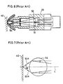
- FIG. 6 An example of a conventional optical code reader available for reading the bar code is shown in FIG. 6.
- the optical code reader is a hand-type and is relatively small in size.
- a light emitting device 51 and a light receiving device 52 are arranged in parallel with each other in a holder 53.
- the emitted light of the light emitting device 51 is focused on a bar code 40 by a ball lens 54 which is positioned in immediate proximity to the bar code 40.
- the light reflected from the bar code 40 is converged by the ball lens 54 and is applied to the light receiving device 52.
- the ball lens 54 with a short focal distance is used, and a distance between the ball lens 54 and the bar code 40 is short. Therefore, an angle ⁇ between the incident light 51A and the reflected light 52A is relatively large.
- the focal point of the incident light 51A is likely deviate from the surface having the bar code even by a slight variation of a distance between the ball lens 54 and the bar code 40 or by tilt of the optical code reader with respect to the surface. And an intensity of the light reflected from the bar code 40 is adversely influenced.
- the surface of the bar code 40 is not always flat but has some concavities or convexities, and it is not so easy to scan the surface of the bar code with a perpendicular posture of the code reader to the surface of the bar code 40. These problems lead to error in reading of the bar code 40. In order to improve the difficulties, the distance between the ball lens 54 and the bar code 40 must be prolonged and the angle ⁇ between the incident light 51A and the reflected light 52A must be reduced.
- the distance between the ball lens 54 and the light emitting device 51 must be further prolonged in order to allow a longer distance between the ball lens 54 and the bar code 40. Consequently, an overall length of the optical code reader becomes larger.
- An object of the present invention is to provide a small-sized optical code reader which is improved in diminution of resolution due to variation of a distance between the optical code reader and the surface of an optical code.
- optical code reader in accordance with the present invention comprises the features of claims 1 or 4.
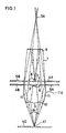
- FIG. 1 is a side view of a first embodiment of an optical code reader in accordance with the present invention.
- a flat mirror 8 is formed on the top surface of a cylindrical member 1, which is made of such as transparent plastics or glass, and the reflecting surface of the flat mirror 8 faces interior of the cylindrical member 1.
- a convex lens 9 as first light converging means is disposed on a central portion of the other end of the cylindrical member 1.
- a ring-shaped transparent portion 10 is formed along the peripheral portion of the convex lens 9.
- a ring-shaped elliptical plane 11A is formed on the side of a lower portion of the cylindrical member 1.
- a specular layer is deposited on the ring-shaped elliptical plane 11A so that an elliptical mirror 11 in which the reflecting surface faces interior of the cylindrical member 1 is formed.
- the elliptical mirror 11 can be realized by forming specular surface on the elliptical plane 11A.
- a light emitting device 3 mounted on one side of a lead frame 4A and facing the flat mirror 8 is placed interiorly of a mid portion of the cylindrical member 1.
- the other surface of the lead frame 4A is attached with the other lead frame 4B with a light interrupting plate 7 therebetween, and a light receiving device 2 is mounted on the other surface of the lead frame 4B so as to face the convex lens 9.
- the light interrupting plate 7 serves as a light interrupting member between the light emitting device 3 and the light receiving device 2.
- a lead frame 5B positioned adjacent to the light emitting device 3 serves as a lead wire of the light emitting device 3.
- Another lead frame 5A positioned adjacent to the light receiving device 2 serves as a lead wire of the light receiving device 2.
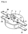
- the shape and placement of the respective lead frames 4A, 4B, 5A and 5B are shown in FIG. 5.
- An electric power for driving the light emitting device 3 is supplied through the lead wires 4A and 5B, and an output of the light receiving device 2 is issued through the lead wires 4B and 5A.
- One focal point of the elliptical mirror 11 is positioned at a symmetrical point 3A of the light emitting device 3 with respect to the flat mirror 8, and the other focal point is positioned at a point 41 which is on a bar code 40.
- Emitted light of the light emitting device 3 are reflected by the flat mirror 8 and are directed to the elliptical mirror 11.
- the light reflected by the elliptical mirror 11 are converged on the focal point 41 on the bar code 40 through the transparent portion 10.
- Light reflected by the bar code 40 is converged on the light receiving device 2 by the convex lens 9.
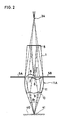
- FIG. 2 shows a second embodiment of the optical code reader in accordance with the present invention.
- the optical system is identical with that of the first embodiment.
- a configuration of lead frames supporting the light emitting device 3 and the light receiving device 2 are different from that of the first embodiment.
- the light emitting device 3 is mounted on one side of a common lead frame 21, and the light receiving device 2 is mounted on the other surface of the lead frame 21.
- FIG. 3 is a perspective view of the common lead frames 21, and connection leads 5A and 5B.
- the lead frame 21 has a circular portion 21A on which the light emitting device 3 and the light receiving device 2 are mounted, and the circular portion 21A serves as a light interrupting plate between the light emitting device 3 and the light receiving device 2.
- a lead frame 5A serves as a lead wire of the light emitting device 3 and a lead frame 5B serves as a lead wire of the light receiving device 2.
- the number of lead frames decreases by using the common lead frame 21, and the light interrupting plate used in the first embodiment can be eliminated. Consequently, manufacturing cost of the optical code reader is reduced.
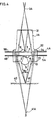
- FIG. 4 is a side view of a third embodiment of the optical code reader in accordance with the present invention.
- a first flat mirror 31 having a reflecting surface facing interior of the cylindrical member 1A, is formed on the upper end surface of a transparent cylindrical member 1A.
- a flange 32 which is larger in diameter than the portion having the first flat mirror 31 is disposed on a mid portion of the cylindrical member 1A.
- the flange 32 is shaped to form an elliptical plane, and an elliptical mirror 34 having a reflecting surface facing interior of the cylindrical member 1A is formed thereon.
- a ring-shaped second flat mirror 33 which is parallel with the first flat mirror 31 is disposed under surface of the flange 32.
- a convex lens 9 is disposed on a central portion of the bottom of the cylindrical member 1A, and a ring-shaped transparent portion 10 is placed between the convex lens 9 and the ring-shaped second flat mirror 33.
- One of two focal points of the elliptical mirror 34 is positioned at a point 41A which is a symmetrical point of a point 3A with respect to the ring-shaped second flat mirror 33, and the other focal pooint is positioned on a point 41 on the bar code 40.
- the arrangement of the lead frames 4A, 4B, 5A and 5B, the light emitting device 3 and the light receiving device 2 is identical with that of the first embodiment as shown in FIG. 1.
- a substantial distance between the light emitting device 3 and the point 41 on the bar code 40 is longer than that of the first embodiment. Consequently, an angle ⁇ 2 of the incident light is smaller than the angle ⁇ 1 in the first embodiment.
- the transparent cylindrical member 1 in the above-mentioned embodiments is tapered on an upper portion thereof above the elliptical mirror, the upper portion may be straight cylinder.
Landscapes
- Physics & Mathematics (AREA)
- Engineering & Computer Science (AREA)
- Electromagnetism (AREA)
- Artificial Intelligence (AREA)
- Toxicology (AREA)
- General Health & Medical Sciences (AREA)
- Health & Medical Sciences (AREA)
- Computer Vision & Pattern Recognition (AREA)
- General Physics & Mathematics (AREA)
- Theoretical Computer Science (AREA)
- Lenses (AREA)
- Length Measuring Devices By Optical Means (AREA)
- Mechanical Optical Scanning Systems (AREA)
- Image Input (AREA)
Description
- The present invention relates generally to an optical code reader, and more particularly to an optical code reader with improved optical system capable of detecting a coded mark such as bar code mark printed on a package of various goods with high reliability.
- A bar code system is widely introduced for identification of various goods by printing or attaching a bar code on goods or packages of the goods sold in department stores, super markets or factories. The bar code is read with an optical code reader to input the data of the bar code into a computer system. Moreover, recently in subscription system for recording a television program in a video tape recorder, channel number, date and time of a television program are presented by a bar code, which is read with a pen-type optical code reader to input the data of the bar code into the video tape recorder.
- An example of a conventional optical code reader available for reading the bar code is shown in FIG. 6. The optical code reader is a hand-type and is relatively small in size. Referring to FIG. 6, a
light emitting device 51 and alight receiving device 52 are arranged in parallel with each other in aholder 53. The emitted light of thelight emitting device 51 is focused on abar code 40 by aball lens 54 which is positioned in immediate proximity to thebar code 40. The light reflected from thebar code 40 is converged by theball lens 54 and is applied to thelight receiving device 52. - In the foregoing conventional optical code reader as shown in FIG.7, the
ball lens 54 with a short focal distance is used, and a distance between theball lens 54 and thebar code 40 is short. Therefore, an angle ϑ between theincident light 51A and thereflected light 52A is relatively large. Thus, the focal point of theincident light 51A is likely deviate from the surface having the bar code even by a slight variation of a distance between theball lens 54 and thebar code 40 or by tilt of the optical code reader with respect to the surface. And an intensity of the light reflected from thebar code 40 is adversely influenced. Furthermore, the surface of thebar code 40 is not always flat but has some concavities or convexities, and it is not so easy to scan the surface of the bar code with a perpendicular posture of the code reader to the surface of thebar code 40. These problems lead to error in reading of thebar code 40. In order to improve the difficulties, the distance between theball lens 54 and thebar code 40 must be prolonged and the angle ϑ between theincident light 51A and thereflected light 52A must be reduced. - In the optical system as shown in FIG. 6, however, the distance between the
ball lens 54 and thelight emitting device 51 must be further prolonged in order to allow a longer distance between theball lens 54 and thebar code 40. Consequently, an overall length of the optical code reader becomes larger. - An object of the present invention is to provide a small-sized optical code reader which is improved in diminution of resolution due to variation of a distance between the optical code reader and the surface of an optical code.
- The optical code reader in acordance with the present invention comprises the features of claims 1 or 4.
- While the novel features of the invention are set forth particularly in the appended claims, the invention, both as to organization and content, will be better understood and appreciated, along with other objects and features thereof, from the following detailed description taken in conjunction with the drawings.
-
- FIG. 1 is a side view of a first embodiment of an optical code reader in accordance with the present invention;
- FIG. 2 is a side view of a second embodiment of an optical code reader in accordance with the present invention;
- FIG. 3 is a perspective view of lead frames of the second embodiment;
- FIG. 4 is a side view of a third embodiment of an optical code reader in accordance with the present invention;
- FIG. 5 is a perspective view of lead frames of the first embodiment and the third embodiment;
- FIG. 6 is the side view of the optical code reader in the prior art;
- FIG. 7 is the detailed side view of the lens of the prior art as shown in FIG. 6.
- It will be recognized that some or all of the Figures are schematic representations for purposes of illustration and do not necessarily depict the actual relative sizes or locations of the elements shown.
- FIG. 1 is a side view of a first embodiment of an optical code reader in accordance with the present invention. Referring to FIG. 1, a flat mirror 8 is formed on the top surface of a cylindrical member 1, which is made of such as transparent plastics or glass, and the reflecting surface of the flat mirror 8 faces interior of the cylindrical member 1. A convex lens 9 as first light converging means is disposed on a central portion of the other end of the cylindrical member 1. A ring-shaped
transparent portion 10 is formed along the peripheral portion of the convex lens 9. Furthermore, a ring-shapedelliptical plane 11A is formed on the side of a lower portion of the cylindrical member 1. A specular layer is deposited on the ring-shapedelliptical plane 11A so that anelliptical mirror 11 in which the reflecting surface faces interior of the cylindrical member 1 is formed. Theelliptical mirror 11 can be realized by forming specular surface on theelliptical plane 11A. - A
light emitting device 3 mounted on one side of alead frame 4A and facing the flat mirror 8 is placed interiorly of a mid portion of the cylindrical member 1. The other surface of thelead frame 4A is attached with theother lead frame 4B with alight interrupting plate 7 therebetween, and alight receiving device 2 is mounted on the other surface of thelead frame 4B so as to face the convex lens 9. Thelight interrupting plate 7 serves as a light interrupting member between thelight emitting device 3 and thelight receiving device 2. - A
lead frame 5B positioned adjacent to thelight emitting device 3 serves as a lead wire of thelight emitting device 3. Anotherlead frame 5A positioned adjacent to thelight receiving device 2 serves as a lead wire of thelight receiving device 2. The shape and placement of therespective lead frames light emitting device 3 is supplied through thelead wires light receiving device 2 is issued through thelead wires - One focal point of the
elliptical mirror 11 is positioned at asymmetrical point 3A of thelight emitting device 3 with respect to the flat mirror 8, and the other focal point is positioned at apoint 41 which is on abar code 40. - Emitted light of the
light emitting device 3 are reflected by the flat mirror 8 and are directed to theelliptical mirror 11. The light reflected by theelliptical mirror 11 are converged on thefocal point 41 on thebar code 40 through thetransparent portion 10. Light reflected by thebar code 40 is converged on the light receivingdevice 2 by the convex lens 9. - In the embodiment, since the light emitted from the
light emitting device 3 is folded by the flat mirror 8, effective distance between thelight emitting device 3 and thefocal point 41 is far longer than the length of the cylindrical member 1, and is also longer than a distance between the convex lens 9 and thebar code 40. Consequently, an incident angle ϑ₁ of the incident light is small, and a permissible deviation of a distance between the end tip of the optical code reader and thebar code 40 with respect to a predetermined diameter of a "permissible circle of confusion" of the incident light at thepoint 40 increases. Hence, deterioration of a dissolving power of the optical code reader due to the deviation of the distance between the optical code reader and thebar code 40 can be improved. - FIG. 2 shows a second embodiment of the optical code reader in accordance with the present invention. In the second embodiment, the optical system is identical with that of the first embodiment. However, a configuration of lead frames supporting the
light emitting device 3 and thelight receiving device 2 are different from that of the first embodiment. Referring to FIG. 2, thelight emitting device 3 is mounted on one side of acommon lead frame 21, and thelight receiving device 2 is mounted on the other surface of thelead frame 21. FIG. 3 is a perspective view of thecommon lead frames 21, and connection leads 5A and 5B. Thelead frame 21 has acircular portion 21A on which thelight emitting device 3 and thelight receiving device 2 are mounted, and thecircular portion 21A serves as a light interrupting plate between thelight emitting device 3 and thelight receiving device 2. Alead frame 5A serves as a lead wire of thelight emitting device 3 and alead frame 5B serves as a lead wire of thelight receiving device 2. - According to the second embodiment, the number of lead frames decreases by using the
common lead frame 21, and the light interrupting plate used in the first embodiment can be eliminated. Consequently, manufacturing cost of the optical code reader is reduced. - FIG. 4 is a side view of a third embodiment of the optical code reader in accordance with the present invention. Referring to FIG. 4, a first
flat mirror 31 having a reflecting surface facing interior of thecylindrical member 1A, is formed on the upper end surface of a transparentcylindrical member 1A. Aflange 32 which is larger in diameter than the portion having the firstflat mirror 31 is disposed on a mid portion of thecylindrical member 1A. Theflange 32 is shaped to form an elliptical plane, and an elliptical mirror 34 having a reflecting surface facing interior of thecylindrical member 1A is formed thereon. A ring-shaped secondflat mirror 33 which is parallel with the firstflat mirror 31 is disposed under surface of theflange 32. A convex lens 9 is disposed on a central portion of the bottom of thecylindrical member 1A, and a ring-shapedtransparent portion 10 is placed between the convex lens 9 and the ring-shaped secondflat mirror 33. One of two focal points of the elliptical mirror 34 is positioned at apoint 41A which is a symmetrical point of apoint 3A with respect to the ring-shaped secondflat mirror 33, and the other focal pooint is positioned on apoint 41 on thebar code 40. The arrangement of the lead frames 4A, 4B, 5A and 5B, thelight emitting device 3 and thelight receiving device 2 is identical with that of the first embodiment as shown in FIG. 1. - According to the third embodiment, a substantial distance between the light emitting
device 3 and thepoint 41 on thebar code 40 is longer than that of the first embodiment. Consequently, an angle ϑ₂ of the incident light is smaller than the angle ϑ₁ in the first embodiment. - In the third embodiment, even in case that the respective positions of the ring-shaped second
flat mirror 33 and the elliptical mirror 34 are reversed, the same result is obtainable. Though the transparent cylindrical member 1 in the above-mentioned embodiments is tapered on an upper portion thereof above the elliptical mirror, the upper portion may be straight cylinder.
Claims (8)
- An optical code reader comprising:
an optical member having
a flat mirror (8) formed on one end of a transparent cylindrical member (1) forming mirror face toward inside of said transparent cylindrical member,
a first light converging means (9) formed on a central portion of the other end of said transparent cylindrical member (1),
a ring-shaped transparent portion (10) formed on a peripheral portion of said first light converging means (9), a light emitting device (3) for emitting light toward said flat mirror (8) interiorly of said transparant cylindrical member, and
a second light converging means (11) formed on side face of said transparent cylindrical member directing the light reflected from the flat mirror through the ring shaped transparant portion to a code
a light receiving device (2) placed interiorly of said transparent cylindrical member for receiving light reflected by the code through said first light converging means. - An optical code reader in accordance with claim 1, wherein
said first light converging means (9) is a convex lens. - An optical code reader in accordance with claim 1, wherein
said second light converging means (11) is an elliptical mirror. - An optical code render comprising:
an optical member having
a flat mirror (31) formed on one end of a transparent cylindrical member (1A) having a flange (32) on mid portion thereof, said flat mirror forming mirror face toward inside of said transparent cylindrical member (1A),
a first light converging means (9) formed on a central portion of the other end of said transparent cylindrical member (1A),
a ring-shaped transparent portion (10) disposed on a peripheral portion of said first light converging means (9),
a ring-shaped flat mirror (33) formed on a peripheral portion of said ring-shaped transparent portion, and
a ring-shaped light converging means (32) formed on said flange,
a light emitting device (3), placed interiorly of said transparent cylindrical member for emitting light toward said flat mirror, said flat mirror reflecting the light towards said ring shaped flat mirror, and said ring shaped light converging means directing the light reflected from said ring shaped flat mirror through said ring shaped transparent portion to a code, and
a light receiving device (2), placed interiorly of said transparent cylindrical member for receiving light reflected by the code through said first light converging means. - An optical code reader in accordance with claim 4, wherein
said first light converging means (9) is a convex lens. - An optical code reader in accordance with claim 4, wherein
said ring-shaped light converging means (34) is a mirror of partial elliptical face having a ring-shaped reflecting surface facing interiorly of said transparent cylindrical member. - An optical code reader in acordance with claim 1 or 4, wherein
a light interrupting member (7) is placed between said light emitting device (3) and said light receiving device (2). - An optical code reader in accordance with claim 1 or 4, wherein
said light emitting device (3) is mounted on a surface of a plate-type lead frame (21) and said light receiving device (2) is mounted on the back surface of said lead frame (21).
Applications Claiming Priority (2)
| Application Number | Priority Date | Filing Date | Title |
|---|---|---|---|
| JP63106320A JPH07101433B2 (en) | 1988-04-28 | 1988-04-28 | Optical pattern detector |
| JP106320/88 | 1988-04-28 |
Publications (3)
| Publication Number | Publication Date |
|---|---|
| EP0339649A2 EP0339649A2 (en) | 1989-11-02 |
| EP0339649A3 EP0339649A3 (en) | 1990-01-03 |
| EP0339649B1 true EP0339649B1 (en) | 1993-10-13 |
Family
ID=14430651
Family Applications (1)
| Application Number | Title | Priority Date | Filing Date |
|---|---|---|---|
| EP89107685A Expired - Lifetime EP0339649B1 (en) | 1988-04-28 | 1989-04-27 | Optical code reader |
Country Status (5)
| Country | Link |
|---|---|
| US (1) | US5184004A (en) |
| EP (1) | EP0339649B1 (en) |
| JP (1) | JPH07101433B2 (en) |
| KR (1) | KR920008507B1 (en) |
| DE (1) | DE68909832T2 (en) |
Families Citing this family (4)
| Publication number | Priority date | Publication date | Assignee | Title |
|---|---|---|---|---|
| KR940010808B1 (en) * | 1989-09-18 | 1994-11-16 | 후지쓰 가부시끼가이샤 | Laser scanner for bar code reader |
| US5332892A (en) * | 1991-07-25 | 1994-07-26 | Symbol Technologies, Inc. | Optical systems for bar code scanners |
| US5319182A (en) * | 1992-03-04 | 1994-06-07 | Welch Allyn, Inc. | Integrated solid state light emitting and detecting array and apparatus employing said array |
| US5635700A (en) * | 1994-07-27 | 1997-06-03 | Symbol Technologies, Inc. | Bar code scanner with multi-channel light collection |
Family Cites Families (17)
| Publication number | Priority date | Publication date | Assignee | Title |
|---|---|---|---|---|
| SE332089B (en) * | 1965-06-14 | 1971-01-25 | Svenska Dataregister Ab | |
| US3784794A (en) * | 1972-10-10 | 1974-01-08 | Nat Bank Of Commerce Of Seattl | Electro-optical reader for bar codes or the like |
| SE368287B (en) * | 1972-10-19 | 1974-06-24 | Svenska Dataregister Ab | |
| US3904277A (en) * | 1974-03-20 | 1975-09-09 | Pitney Bowes Inc | Optical hand scanner optical assembly |
| US3920959A (en) * | 1974-04-22 | 1975-11-18 | Nixdorf Computer Ag | Opto-electronic sensing rod for the manual scanning of graphic information |
| US3911270A (en) * | 1974-08-28 | 1975-10-07 | Identicon Corp | Light pen reading |
| US4143809A (en) * | 1977-10-11 | 1979-03-13 | Hewlett-Packard Company | Optical bar code reader |
| FR2460523A1 (en) * | 1979-06-29 | 1981-01-23 | Thomson Csf | SEMICONDUCTOR LASER SOURCE OPTICAL READING HEAD AND DEVICE FOR REFLECTING AN INFORMATION MEDIUM COMPRISING SUCH AN OPTICAL HEAD |
| FR2479510B1 (en) * | 1980-04-01 | 1986-03-14 | Sagem | IMPROVEMENTS ON OPTICAL DOCUMENT ANALYSIS DEVICES |
| FR2487551A1 (en) * | 1980-07-25 | 1982-01-29 | Videoton Elekt Vallalat | OPTO-ELECTRONIC LIGHTING AND DETECTION APPARATUS ON A MEDIUM |
| JPS6125660U (en) * | 1984-07-20 | 1986-02-15 | 日新工機株式会社 | pen type barcode reader |
| DE3686171T2 (en) * | 1985-02-28 | 1993-03-18 | Symbol Technologies Inc | PORTABLE SCAN HEAD WITH LASER DIODE. |
| US4675531A (en) * | 1985-03-28 | 1987-06-23 | Polaroid Corporation | Optical scanner having a multi-surfaced lens arrangement for producing a rotationally symmetric beam |
| JPH0617253Y2 (en) * | 1985-12-05 | 1994-05-02 | 株式会社日本コンラックス | Optical memory card reader |
| US4877949A (en) * | 1986-08-08 | 1989-10-31 | Norand Corporation | Hand-held instant bar code reader system with automated focus based on distance measurements |
| US4797551A (en) * | 1987-06-11 | 1989-01-10 | Ncr Corporation | Compact laser scanner optical system |
| US4851667A (en) * | 1987-11-16 | 1989-07-25 | Ncr Corporation | Compact laser scanner optical system |
-
1988
- 1988-04-28 JP JP63106320A patent/JPH07101433B2/en not_active Expired - Fee Related
-
1989
- 1989-04-27 EP EP89107685A patent/EP0339649B1/en not_active Expired - Lifetime
- 1989-04-27 US US07/344,089 patent/US5184004A/en not_active Expired - Fee Related
- 1989-04-27 DE DE89107685T patent/DE68909832T2/en not_active Expired - Fee Related
- 1989-04-28 KR KR1019890005648A patent/KR920008507B1/en not_active Expired
Also Published As
| Publication number | Publication date |
|---|---|
| EP0339649A2 (en) | 1989-11-02 |
| EP0339649A3 (en) | 1990-01-03 |
| DE68909832D1 (en) | 1993-11-18 |
| JPH07101433B2 (en) | 1995-11-01 |
| KR920008507B1 (en) | 1992-09-30 |
| DE68909832T2 (en) | 1994-02-10 |
| US5184004A (en) | 1993-02-02 |
| KR900016734A (en) | 1990-11-14 |
| JPH01276383A (en) | 1989-11-06 |
Similar Documents
| Publication | Publication Date | Title |
|---|---|---|
| EP0348232B1 (en) | Optical beam scanner for reading bar-codes | |
| US4675531A (en) | Optical scanner having a multi-surfaced lens arrangement for producing a rotationally symmetric beam | |
| JPS622689Y2 (en) | ||
| US4408120A (en) | Bar code scanner | |
| US4743773A (en) | Bar code scanner with diffusion filter and plural linear light source arrays | |
| EP1045329B1 (en) | Optical assembly having lens offset from optical axis | |
| US6069727A (en) | Laser scanning unit | |
| US5136145A (en) | Symbol reader | |
| JPS62147576A (en) | Pattern reader | |
| US5283699A (en) | Micro-bar code reader system | |
| US5184004A (en) | Optical code reader | |
| CA1101121A (en) | Twisting geometry scanner | |
| CA2020540C (en) | Bar code reader | |
| US6350980B1 (en) | Imaging assembly with a side mounted optical detector for a scanner | |
| US5610385A (en) | Optical bar code scanner which produces substantially perpendicular scan lines | |
| CN113901851B (en) | Linear bar code scanner | |
| KR930005044Y1 (en) | Barcode Laser Scanner Optics | |
| JP3068949B2 (en) | Reader | |
| JPH0124665Y2 (en) | ||
| JPH087767B2 (en) | Optical reader | |
| JPH02161578A (en) | barcode scanner | |
| JPS61277253A (en) | optical image reading device | |
| JPH03142967A (en) | Close contact type image sensor | |
| JP2005217500A (en) | Image reading device | |
| JPH0497212A (en) | Laser beam scanner |
Legal Events
| Date | Code | Title | Description |
|---|---|---|---|
| PUAI | Public reference made under article 153(3) epc to a published international application that has entered the european phase |
Free format text: ORIGINAL CODE: 0009012 |
|
| 17P | Request for examination filed |
Effective date: 19890427 |
|
| AK | Designated contracting states |
Kind code of ref document: A2 Designated state(s): DE FR GB |
|
| PUAL | Search report despatched |
Free format text: ORIGINAL CODE: 0009013 |
|
| AK | Designated contracting states |
Kind code of ref document: A3 Designated state(s): DE FR GB |
|
| 17Q | First examination report despatched |
Effective date: 19930202 |
|
| GRAA | (expected) grant |
Free format text: ORIGINAL CODE: 0009210 |
|
| AK | Designated contracting states |
Kind code of ref document: B1 Designated state(s): DE FR GB |
|
| REF | Corresponds to: |
Ref document number: 68909832 Country of ref document: DE Date of ref document: 19931118 |
|
| ET | Fr: translation filed | ||
| PLBE | No opposition filed within time limit |
Free format text: ORIGINAL CODE: 0009261 |
|
| STAA | Information on the status of an ep patent application or granted ep patent |
Free format text: STATUS: NO OPPOSITION FILED WITHIN TIME LIMIT |
|
| 26N | No opposition filed | ||
| REG | Reference to a national code |
Ref country code: GB Ref legal event code: IF02 |
|
| PGFP | Annual fee paid to national office [announced via postgrant information from national office to epo] |
Ref country code: GB Payment date: 20040421 Year of fee payment: 16 |
|
| PGFP | Annual fee paid to national office [announced via postgrant information from national office to epo] |
Ref country code: DE Payment date: 20040506 Year of fee payment: 16 |
|
| PGFP | Annual fee paid to national office [announced via postgrant information from national office to epo] |
Ref country code: FR Payment date: 20050408 Year of fee payment: 17 |
|
| PG25 | Lapsed in a contracting state [announced via postgrant information from national office to epo] |
Ref country code: GB Free format text: LAPSE BECAUSE OF NON-PAYMENT OF DUE FEES Effective date: 20050427 |
|
| PG25 | Lapsed in a contracting state [announced via postgrant information from national office to epo] |
Ref country code: DE Free format text: LAPSE BECAUSE OF NON-PAYMENT OF DUE FEES Effective date: 20051101 |
|
| GBPC | Gb: european patent ceased through non-payment of renewal fee |
Effective date: 20050427 |
|
| REG | Reference to a national code |
Ref country code: FR Ref legal event code: ST Effective date: 20061230 |
|
| PG25 | Lapsed in a contracting state [announced via postgrant information from national office to epo] |
Ref country code: FR Free format text: LAPSE BECAUSE OF NON-PAYMENT OF DUE FEES Effective date: 20060502 |