EP0339615B1 - Labeling apparatus for attaching a label onto a predetermined position on articles - Google Patents
Labeling apparatus for attaching a label onto a predetermined position on articles Download PDFInfo
- Publication number
- EP0339615B1 EP0339615B1 EP19890107568 EP89107568A EP0339615B1 EP 0339615 B1 EP0339615 B1 EP 0339615B1 EP 19890107568 EP19890107568 EP 19890107568 EP 89107568 A EP89107568 A EP 89107568A EP 0339615 B1 EP0339615 B1 EP 0339615B1
- Authority
- EP
- European Patent Office
- Prior art keywords
- labeling
- article
- angular
- degree
- drum
- Prior art date
- Legal status (The legal status is an assumption and is not a legal conclusion. Google has not performed a legal analysis and makes no representation as to the accuracy of the status listed.)
- Expired - Lifetime
Links
- 238000002372 labelling Methods 0.000 title claims description 144
- 230000010363 phase shift Effects 0.000 claims description 15
- 238000006073 displacement reaction Methods 0.000 claims description 8
- 238000000034 method Methods 0.000 claims description 6
- 238000012544 monitoring process Methods 0.000 claims 1
- 239000011295 pitch Substances 0.000 description 5
- 230000006835 compression Effects 0.000 description 3
- 238000007906 compression Methods 0.000 description 3
- 239000000853 adhesive Substances 0.000 description 2
- 230000001070 adhesive effect Effects 0.000 description 2
- 230000001360 synchronised effect Effects 0.000 description 2
- NCGICGYLBXGBGN-UHFFFAOYSA-N 3-morpholin-4-yl-1-oxa-3-azonia-2-azanidacyclopent-3-en-5-imine;hydrochloride Chemical compound Cl.[N-]1OC(=N)C=[N+]1N1CCOCC1 NCGICGYLBXGBGN-UHFFFAOYSA-N 0.000 description 1
- 230000002159 abnormal effect Effects 0.000 description 1
- 230000001419 dependent effect Effects 0.000 description 1
- 238000010586 diagram Methods 0.000 description 1
- 230000007257 malfunction Effects 0.000 description 1
- 238000004519 manufacturing process Methods 0.000 description 1
- 238000003825 pressing Methods 0.000 description 1
- 230000000644 propagated effect Effects 0.000 description 1
Images


Classifications
-
- B—PERFORMING OPERATIONS; TRANSPORTING
- B65—CONVEYING; PACKING; STORING; HANDLING THIN OR FILAMENTARY MATERIAL
- B65C—LABELLING OR TAGGING MACHINES, APPARATUS, OR PROCESSES
- B65C9/00—Details of labelling machines or apparatus
- B65C9/40—Controls; Safety devices
- B65C9/42—Label feed control
-
- B—PERFORMING OPERATIONS; TRANSPORTING
- B65—CONVEYING; PACKING; STORING; HANDLING THIN OR FILAMENTARY MATERIAL
- B65B—MACHINES, APPARATUS OR DEVICES FOR, OR METHODS OF, PACKAGING ARTICLES OR MATERIALS; UNPACKING
- B65B57/00—Automatic control, checking, warning, or safety devices
- B65B57/10—Automatic control, checking, warning, or safety devices responsive to absence, presence, abnormal feed, or misplacement of articles or materials to be packaged
Definitions
- the present invention relates generally to a labeling system as disclosed in EP-A-0 033 609 and recited in the preamble of claim 1 and more particularly to a labeling system including a means for adjusting a tolerance of labeling position relative to a given area such as bottles in a sequential labeling operation.
- a further conventional labeling apparatus for attaching a label to vessels as disclosed in FR-B-1 247 933 includes a vessel positioning mechanism, for example, a screw unit which is mechanically synchronized with the rotation of a labeling drum is provided at a vessel positioning station.
- the vessel positioning mechanism is operable to provide a constant carrying pitch between the vessels on a conveyor so as to determine a position where a label is attached to the vessel, or a relative labeling position with respect to the drum.
- the vessels after being positioned at a given interval, are carried to a labeling station.
- a label magazine provides labels to the labeling drum in sequence.
- the labels are backed with adhesive by an adhesion roller and then are provisionally affixed to the vessels carried on the conveyor.
- the labeled vessels are fed to a final finishing section and are pressed moderately by a compression unit.
- This sequential labeling operation is effected by a driver which is mechanically connected to a single driving source provided in the labeling system.
- the positioning of vessels with respect to the labeling drum is important. Only when the relative position of the vessel with respect to the labeling head provided on a labeling drum is determined precisely can accurate labeling be provided.
- an object of the present invention to provide a labeling apparatus for attaching a label accurately to a given area on articles such as bottles in a sequential labeling operation, and a method therefor.
- the present invention is based on a labeling apparatus for attaching labels onto articles wherein a specific point defined on a label aligns with a predetermined position on an article, which comprises a first means for feeding the articles toward a labeling station at given carrying intervals, a second means, provided at the labeling station, for providing labels to articles at given labeling intervals which corresponds to the given carrying intervals, a third means for determining a relative degree of shift between the predetermined position on an article fed by the first means and the specific point on a label provided by the second means, and a fourth means for adjusting the labeling interval of the second means based on the relative degree of shift so that the specific point on the label corresponds to the predetermined labeling point on the article.
- the second means is a rotary labeling drum having a plurality of labeling heads at regular intervals which respectively dispense labels.
- the third means includes a photo sensor for sensing an article carried by a conveyor as the first means, and a rotary encoder for detecting the angular position of the rotary labeling drum.
- the labeling position is defined by the exact coincidence of the specific point on a label provided on the labeling head with the predetermined position on an article at the labeling station.
- the third means determines a degree of angular displacement of the rotary labeling drum based on a signal output by the rotary encoder after the labeling head passes the labeling point until another article is sensed by the photo sensor to calculate a degree of phase shift of the angular position of the rotary labeling drum from the given labeling interval.
- the fourth means adjusts the rotation of said labeling rotary drum so as to implement said degree of phase shift.
- This system comprises generally an input screw unit 1 functioning as a positioner for vessels 5, a conveyer 2 for carrying vessels, a labeling station 3 for providing a label to the vessels, and compression units 4 for pressing the label attached to the vessel.
- the vessels 5, such as bottles are positioned by the input screw unit 1 at a given interval and are carried on a belt of the conveyer 2 toward the labeling station 3.
- the labeling station includes a rotary labeling drum 12, labeling heads 15, an adhesion roller unit 16, and a label magazine 8.
- the rotary labeling drum 12 is rotatably supported by gearing (not shown) disposed beneath the labeling station and is driven by a drive motor 6 through a gear assembly 20 so as to be mechanically synchronized with the rotation of the input screw unit 1 via a main drive shaft 14.
- the synchronization determines a carrying pitch between the vessels 5 on the conveyer 2 to provide precise sequential labeling.
- labeling heads are arranged, for example, at six intervals.
- the label magazine provides a label to the labeling heads in sequence.
- the adhesion roller unit 16 provides an adhesive onto the reverse surface of the label provided on the head 15. Thereafter, this label is attached to a given area of a vessel 5 carried by the conveyer 2.
- Such a sequential labeling operation is effected by the precise synchronization of the input screw unit 1 with the rotary labeling drum 12.
- the synchronization is however subject to slippage due to shifts in vessel position caused by gripping, or misregistration of the vessel on the conveyer 2 or backlash from the drive caused by wear of gears for example. Therefore, in the labeling system according to the invention, a means for compensating for a degree of shift of the vessel with respect to a head of a rotary labeling drum is provided.
- This means includes a differential gear 13, a servo motor 7 therefor, a photo sensor 10, and a controller 9.
- the photo sensor 10 is adapted for sensing the position of a vessel carried on the conveyer and to provide a signal indicative thereof to the controller 9.
- the controller determines the relative degree of shift between each vessel 5, or a predetermined position defined thereon and a corresponding head of a rotary labeling drum 12.
- the differential gear 13 is driven by a servo motor 7 according to the value of the relative degree of shift.
- the differential gear 13 is mechanically connected to a gear (not shown) disposed beneath the labeling station 3 via a shaft 22. This gear rotates the rotary labeling drum 12 so as to advance or retard the rotation thereof independent of the drive motor 6 to compensate for any shift in vessel position to maintain accurate label placement.
- the vessel is pressed by a pair of pads at the compression unit 4 to finish the sequential labeling operation
- the means further includes a rotary encoder 11.
- the rotary encoder 11 is installed on the rotary labeling drum 12 so as to monitor an angle of rotation thereof and provides pulse signals of an ⁇ A ⁇ , a ⁇ B ⁇ , and a ⁇ Z ⁇ phase indicative of the angular position of the drum to the controller 9 (As is well known in the art, a rotary encoder is adapted for providing an A phase pulse signal, a B phase pulse signal, and a Z phase pulse signal.
- the B phase pulse signal is shifted 90 degrees from the-A phase pulse signal.
- the Z phase pulse signal is a reference signal which is output every cycle).
- an interface circuit (not shown) for the rotary encoder is provided. This circuit detects the leading edges of pulse signals of the A and B phases.
- the downcounter receives P number of pulse signals for every cycle of the rotary labeling drum 12 and indicates a value within 0 to -(P-1) (0 to -14399). (Thus, since six labeling heads are provided on the rotary labeling drum, the angle between each corresponds to 2400 pulse signals. These 2400 pulse signals correspond to the carrying pitch of the vessels.)
- the sensor senses the leading edge of the vessel and provides a signal to the controller 9 to interrupt the CPU.
- the CPU reads the value of the downcounter and can convert this value into to provide an integer value within 0 to (P-1) (0 to 14339) as the phase angle of the rotary labeling drum 12.
- the phase difference (R) is the degree of displacement of a labeling head past a labeling point defined by the exact coincidence of the labeling head with the predetermined position of the articles at the labeling station.
- the number of pulses defining R are counted beginning at the labeling point and ending when the photo sensor 10 encounters the leading edge of the next vessel. (as in Fig. 2)
- the value ⁇ R ⁇ is variable dependent on the degree of shift of the vessel with respect to the head of the rotary labeling drum.
- this certain value is ⁇ C ⁇
- the controller 9 After obtaining the deflection E, the controller 9 provides pulse signals of a number corresponding to the deflection E to the servo motor 7.
- the servo motor 7 rotates the labeling drum by an angle corresponding to Y number of pulse signals via the differential gear thereby correcting for the shift of a vessel 5 with respect to the corresponding head of the label holder 15.
- a sequential correction control for phase shift as described above is repeated every carrying pitch and the labeling is thus effected regularly.
- the CPU breaks off outputting the pulse signals at a predetermined tolerance point in order to protect the mechanical system.
- the deflection E is small, (e.i., the absolute value of the deflection E is within a certain range ⁇ M ⁇ ) no adjusting operation is provided.
- the ⁇ Yb ⁇ is a number of the output pulse signals at the previous adjusting operation, while the ⁇ B ⁇ is a value into which backlash as an error due to reversion of the differential gear 13 is converted and is a proper value defined by the type of differential gears employed.
- FIG. 3 shows a sensor 30 suitable for box shaped vessels.
- This sensor is comprised of a light source 32 and a light receiving means 34.
- the light receiving means includes a plurality of light receiving elements sensitive to the light beam from the light source.
- the controller 9 can determine the degree of angular displacement of the predetermined position on the vessel in response to the signal output from an element of the light receiving means.
- Fig. 4 shows a sensor means 40 suitable for cylindrical vessels.
- a cylindrical vessel such as a bottle usually has a spot 42 for setting its angular position at a positioning section of the labeling system.
- the sensor means 40 includes a camera 42 and an image measuring apparatus 46 connected to the controller 9. The camera provides an image signal of the spot on the vessel carried on the conveyer 2 to an image measuring apparatus 46.
- the sensor means 40 can thereby detect angular misregistration of the vessel on the conveyer 2 and, if present, determine the degree of angular displacement thereof.
- FIG. 5 an angular and positional relationship between the vessel and the labeling head 15 is shown.
- the shown vessel 5 has been displaced by a distance ⁇ x ⁇ opposite the carrying direction and is shifted by a ⁇ - ⁇ ⁇ angle in the clockwise direction.
- the distance between the center of the labeling head (i.e., a specific point defined on the label provided on the labeling head) and the point of contact ⁇ C ⁇ or the arc OC is R ⁇
- the distance between the center of the vessel and the point of contact C, or the arc LC is -r(- ⁇ - ⁇ ).
- the ⁇ is set up as in the following equation.
- the controller 9 can output Y number of pulse signals to the servo motor 7 to adjust the labeling interval of the labeling drum as necessary so that the specific point on the label aligns with the predetermined position on the vessel.
- the labeling system according to the invention is adapted for measuring the pitches between vessels carried on a conveyer and/or an angular misregistration of the vessels to calculate a degree of shift between a given labeling area of the vessel and the corresponding labeling head of the labeling drum and for driving a servo motor to adjust the angle of rotation of the rotary labeling drum.
- the present invention is not limited to the above embodiment of a carrying mechanism for vessels.
- a differential gear may be provided in a driver for a vessel carrying rotary table 17 and the angle of rotation of the table can be controlled to adjust for phase shift between a vessel and a corresponding labeling head.
Landscapes
- Engineering & Computer Science (AREA)
- Mechanical Engineering (AREA)
- Labeling Devices (AREA)
Description
- The present invention relates generally to a labeling system as disclosed in EP-A-0 033 609 and recited in the preamble of
claim 1 and more particularly to a labeling system including a means for adjusting a tolerance of labeling position relative to a given area such as bottles in a sequential labeling operation. - A further conventional labeling apparatus for attaching a label to vessels as disclosed in FR-B-1 247 933 includes a vessel positioning mechanism, for example, a screw unit which is mechanically synchronized with the rotation of a labeling drum is provided at a vessel positioning station. The vessel positioning mechanism is operable to provide a constant carrying pitch between the vessels on a conveyor so as to determine a position where a label is attached to the vessel, or a relative labeling position with respect to the drum. The vessels, after being positioned at a given interval, are carried to a labeling station.
- At the labeling station, a label magazine provides labels to the labeling drum in sequence. The labels are backed with adhesive by an adhesion roller and then are provisionally affixed to the vessels carried on the conveyor. After labeling, the labeled vessels are fed to a final finishing section and are pressed moderately by a compression unit. This sequential labeling operation is effected by a driver which is mechanically connected to a single driving source provided in the labeling system.
- In such a sequential labeling operation, the positioning of vessels with respect to the labeling drum is important. Only when the relative position of the vessel with respect to the labeling head provided on a labeling drum is determined precisely can accurate labeling be provided.
- However, in conventional labeling technique, relative position of the vessel with respect to the labeling head is subjected to variance due to shifting or gripping of the vessel with respect to the conveyor or backlash caused by the wear of gears in a drive mechanism for example. As a result, the label is shifted with regard to its intended position on the vessel and when attached thereon, results in the production of non-conforming vessels.
- It is, accordingly, an object of the present invention to provide a labeling apparatus for attaching a label accurately to a given area on articles such as bottles in a sequential labeling operation, and a method therefor.
- This object is met by the apparatus defined in
claim 1 and by the method defined inclaim 6. - Accordingly, the present invention is based on a labeling apparatus for attaching labels onto articles wherein a specific point defined on a label aligns with a predetermined position on an article, which comprises a first means for feeding the articles toward a labeling station at given carrying intervals, a second means, provided at the labeling station, for providing labels to articles at given labeling intervals which corresponds to the given carrying intervals, a third means for determining a relative degree of shift between the predetermined position on an article fed by the first means and the specific point on a label provided by the second means, and a fourth means for adjusting the labeling interval of the second means based on the relative degree of shift so that the specific point on the label corresponds to the predetermined labeling point on the article.
- It is characterized in that the second means is a rotary labeling drum having a plurality of labeling heads at regular intervals which respectively dispense labels. The third means includes a photo sensor for sensing an article carried by a conveyor as the first means, and a rotary encoder for detecting the angular position of the rotary labeling drum. The labeling position is defined by the exact coincidence of the specific point on a label provided on the labeling head with the predetermined position on an article at the labeling station. The third means determines a degree of angular displacement of the rotary labeling drum based on a signal output by the rotary encoder after the labeling head passes the labeling point until another article is sensed by the photo sensor to calculate a degree of phase shift of the angular position of the rotary labeling drum from the given labeling interval. The fourth means adjusts the rotation of said labeling rotary drum so as to implement said degree of phase shift.
- The present invention will be understood from the detailed description given hereinbelow and from the accompanying drawings of the preferred embodiment which are given for explanation and understanding only and are not intended to imply limitation to the invention.
- Fig. 1 is a schematic diagram which shows a labeling system according to the present invention.
- Fig. 2 is a schematic representation which shows a degree of positional shift of vessels on a conveyer.
- Fig. 3 is a schematic view which shows an angular sensor means suitable for box shaped vessels which detects angular misregistration thereof on the conveyer.
- Fig. 4 is a schematic view which shows another type of angular sensor means as shown in Fig. 3.
- Fig. 5 is an explanatory view which shows an angular and positional relationship between a vessel and a labeling head.
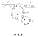
- Fig. 6 is a schematic plan view which shows a second embodiment of a vessel carrying mechanism.
- Referring now to the drawings, particularly to Fig. 1, there is shown a labeling system according to the present invention. This system comprises generally an
input screw unit 1 functioning as a positioner forvessels 5, aconveyer 2 for carrying vessels, a labeling station 3 for providing a label to the vessels, andcompression units 4 for pressing the label attached to the vessel. - The
vessels 5, such as bottles are positioned by theinput screw unit 1 at a given interval and are carried on a belt of theconveyer 2 toward the labeling station 3. The labeling station includes arotary labeling drum 12, labelingheads 15, anadhesion roller unit 16, and alabel magazine 8. Therotary labeling drum 12 is rotatably supported by gearing (not shown) disposed beneath the labeling station and is driven by adrive motor 6 through agear assembly 20 so as to be mechanically synchronized with the rotation of theinput screw unit 1 via amain drive shaft 14. The synchronization determines a carrying pitch between thevessels 5 on theconveyer 2 to provide precise sequential labeling. On the circumference of the rotary labelingdrum 12, labeling heads are arranged, for example, at six intervals. The label magazine provides a label to the labeling heads in sequence. Theadhesion roller unit 16 provides an adhesive onto the reverse surface of the label provided on thehead 15. Thereafter, this label is attached to a given area of avessel 5 carried by theconveyer 2. - Such a sequential labeling operation is effected by the precise synchronization of the
input screw unit 1 with therotary labeling drum 12. The synchronization is however subject to slippage due to shifts in vessel position caused by gripping, or misregistration of the vessel on theconveyer 2 or backlash from the drive caused by wear of gears for example. Therefore, in the labeling system according to the invention, a means for compensating for a degree of shift of the vessel with respect to a head of a rotary labeling drum is provided. This means includes adifferential gear 13, a servo motor 7 therefor, aphoto sensor 10, and acontroller 9. Thephoto sensor 10 is adapted for sensing the position of a vessel carried on the conveyer and to provide a signal indicative thereof to thecontroller 9. The controller determines the relative degree of shift between eachvessel 5, or a predetermined position defined thereon and a corresponding head of arotary labeling drum 12. During the labeling operation, thedifferential gear 13 is driven by a servo motor 7 according to the value of the relative degree of shift. Thedifferential gear 13 is mechanically connected to a gear (not shown) disposed beneath the labeling station 3 via ashaft 22. This gear rotates therotary labeling drum 12 so as to advance or retard the rotation thereof independent of thedrive motor 6 to compensate for any shift in vessel position to maintain accurate label placement. After labeling in the labeling station, the vessel is pressed by a pair of pads at thecompression unit 4 to finish the sequential labeling operation - The means further includes a rotary encoder 11. The rotary encoder 11 is installed on the
rotary labeling drum 12 so as to monitor an angle of rotation thereof and provides pulse signals of an ˝A˝, a ˝B˝, and a ˝Z˝ phase indicative of the angular position of the drum to the controller 9 (As is well known in the art, a rotary encoder is adapted for providing an A phase pulse signal, a B phase pulse signal, and a Z phase pulse signal. The B phase pulse signal is shifted 90 degrees from the-A phase pulse signal. The Z phase pulse signal is a reference signal which is output every cycle). In thecontroller 9, an interface circuit (not shown) for the rotary encoder is provided. This circuit detects the leading edges of pulse signals of the A and B phases. The frequencies of these pulse signals are multiplied by four and counted by a sixteen bit downcounter. When the first pulse of the Z phase signal is detected, the CPU is interrupted and the downcounter is reset to ˝0˝ through the system software. It will be understood that pulse signals output from the rotary encoder are meaningless until the Z phase signal is input to the controller each cycle. Between cycles an indicator provided on a control panel of the controller shows nothing. - The downcounter receives P number of pulse signals for every cycle of the
rotary labeling drum 12 and indicates a value within 0 to -(P-1) (0 to -14399). (Thus, since six labeling heads are provided on the rotary labeling drum, the angle between each corresponds to 2400 pulse signals. These 2400 pulse signals correspond to the carrying pitch of the vessels.) When thevessel 5 is carried within a detecting range of thephoto sensor 10, the sensor senses the leading edge of the vessel and provides a signal to thecontroller 9 to interrupt the CPU. At this time, the CPU reads the value of the downcounter and can convert this value into to provide an integer value within 0 to (P-1) (0 to 14339) as the phase angle of therotary labeling drum 12. Assuming that the integer value is ˝RE˝, the phase difference (R) is the degree of displacement of a labeling head past a labeling point defined by the exact coincidence of the labeling head with the predetermined position of the articles at the labeling station. The number of pulses defining R are counted beginning at the labeling point and ending when thephoto sensor 10 encounters the leading edge of the next vessel. (as in Fig. 2) This value can be expressed as follows;

It will be noted that the R is the remainder when RE X a number of heads is divided by P. The value ˝R˝ is variable dependent on the degree of shift of the vessel with respect to the head of the rotary labeling drum. However, in view of possible error in the mounting position of the photosensor 10 with regard to labeling position, and tolerances necessary due to the different detected positions of different kinds of vessels, addition of a certain constant value to the R value is practically necessary. Accordingly, if this certain value is ˝C˝, the degree of deflection E necessary to align thelabeling head 15 with the real position of theoncoming vessel 5 is obtained by the following equation.

- After obtaining the deflection E, the
controller 9 provides pulse signals of a number corresponding to the deflection E to the servo motor 7. The relationship between the input pulse signals from the rotary encoder 11 and the output pulse signals to the the servo motor 7 is as follows:

- Accordingly, the number of output pulse signals ˝Y˝ to the servo motor driving system with respect to the deflection E is as follows:

Thus, the servo motor 7 rotates the labeling drum by an angle corresponding to Y number of pulse signals via the differential gear thereby correcting for the shift of avessel 5 with respect to the corresponding head of thelabel holder 15. A sequential correction control for phase shift as described above is repeated every carrying pitch and the labeling is thus effected regularly. - In view of a malfunction of the
photo sensor 10, or an abnormal status where a carried vessel passes over the control range of the labeling system, meaning that the output signal Y exceeds the number of pulse signals corresponding to a range of ± 10 (mm), the CPU breaks off outputting the pulse signals at a predetermined tolerance point in order to protect the mechanical system. Taking account of the decrease in the lifespan of the driving system caused by wear thereof due to frequent adjusting operations, preferably, when the deflection E is small, (e.i., the absolute value of the deflection E is within a certain range ˝M˝) no adjusting operation is provided. - Further, in view of backlash of the
differential gear 13, the following functions may be provided for a higher adjustment. The following formula replaces the above equation (2).
If Yb > 0 and E > 0, then
If Yb > 0 and E < 0, then
If Yb < 0 and E > 0, then
If Yb < 0 and E < 0, then
Wherein the ˝Yb˝ is a number of the output pulse signals at the previous adjusting operation, while the ˝B˝ is a value into which backlash as an error due to reversion of thedifferential gear 13 is converted and is a proper value defined by the type of differential gears employed. - Referring to Figs. 3 and 4, an angle detecting means for detecting an angular position of the vessels, (or the predetermined labeling position thereon) on the conveyer is shown. In sequential labeling operations, angular misregistration of the vessels tends to occur in addition to the above described positional shift on the conveyer. Fig 3 shows a
sensor 30 suitable for box shaped vessels. This sensor is comprised of alight source 32 and a light receiving means 34. The light receiving means includes a plurality of light receiving elements sensitive to the light beam from the light source. When thevessel 5 is carried within detecting range of thesensor 30 with a correct angular position, a light beam propagated from thelight source 32 is reflected on a side surface of the vessel at its center and is directed to a predetermined light receiving element of the light receiving means 34. Thedevice 34 provides a signal indicative of the correct angular position to thecontroller 9. On the other hand, when thevessel 5 is carried with an angular misregistration, the light beam reflected from the surface of the vessel is shifted laterally with respect to the elements on the light receiving means. Thus, thecontroller 9 can determine the degree of angular displacement of the predetermined position on the vessel in response to the signal output from an element of the light receiving means. - Fig. 4 shows a sensor means 40 suitable for cylindrical vessels. A cylindrical vessel such as a bottle usually has a
spot 42 for setting its angular position at a positioning section of the labeling system. The sensor means 40 includes acamera 42 and animage measuring apparatus 46 connected to thecontroller 9. The camera provides an image signal of the spot on the vessel carried on theconveyer 2 to animage measuring apparatus 46. The sensor means 40 can thereby detect angular misregistration of the vessel on theconveyer 2 and, if present, determine the degree of angular displacement thereof. - Referring to Fig. 5, an angular and positional relationship between the vessel and the
labeling head 15 is shown. The shownvessel 5 has been displaced by a distance ˝x˝ opposite the carrying direction and is shifted by a ˝-ϑ˝ angle in the clockwise direction. Accordingly, the distance between the center of the labeling head (i.e., a specific point defined on the label provided on the labeling head) and the point of contact ˝C˝ or the arc OC is Rα, while the distance between the center of the vessel and the point of contact C, or the arc LC is -r(-ϑ-α). The α is set up as in the following equation.

wherein Z is the distance between the predetermined position on thearticle 5 and the center point thereof.
However, the above equation can be considered as the following approximate equation.

Thus, the degree of shift of the label, i.e., the deflection ˝E˝ is as follows:
Wherein the x corresponds to the previous equation (1). Accordingly, from the equation (2), the number of output pulse signals Y is as follows:

Thecontroller 9 can output Y number of pulse signals to the servo motor 7 to adjust the labeling interval of the labeling drum as necessary so that the specific point on the label aligns with the predetermined position on the vessel. - The labeling system according to the invention, as described above, is adapted for measuring the pitches between vessels carried on a conveyer and/or an angular misregistration of the vessels to calculate a degree of shift between a given labeling area of the vessel and the corresponding labeling head of the labeling drum and for driving a servo motor to adjust the angle of rotation of the rotary labeling drum. However, the present invention is not limited to the above embodiment of a carrying mechanism for vessels. For example, in a rotary type labeling system as shown in Fig. 3, a differential gear may be provided in a driver for a vessel carrying rotary table 17 and the angle of rotation of the table can be controlled to adjust for phase shift between a vessel and a corresponding labeling head.
Claims (8)
- A labeling apparatus for attaching labels onto articles, wherein a specific point defined on a label aligns with a predetermined position on an article, comprising:
first means (1) for feeding the articles (5) on a conveyor (2) in a carrying direction toward a labeling station (3) at given carrying intervals;
second means provided at said labeling station for providing the labels to articles (5) at given labeling intervals which correspond to the given carrying intervals;
third means including a first sensor (10) for detecting the position of the article (5) on the conveyor (2) with respect to the carrying direction so as to obtain, within a range of one carrying interval before a labeling point, which is defined by the coincidence of the specific point on an article (5) at the labeling station (3), a signal indicative thereof; and
fourth means (7, 9, 13) responsive to the signal from said third means for controlling said second means so that the specific point on a label corresponds to the predetermined position on said article (5) detected by the first sensor (10),
characterized in that
said second means include a rotary labeling drum (12), having a plurality of labeling heads (15) which respectively dispense labels,
said third means further includes a second sensor (11) for detecting angular positions of the labeling heads (15) to provide signals indicative thereof, said third means determining, in response to the signal from the first sensor (10), an angular position of the labeling head (15) which corresponds to the position of the article (5) detected by the first sensor (10) to calculate a degree of phase shift of the angular position of the labeling head (15) from the given labeling interval based on the signal from said second sensor (11),
said fourth means (7, 9, 13) adjusting the rotation of said rotary labeling drum (12) to eliminate the degree of phase shift. - An apparatus as set forth in claim 1, characterized in that said first means (1) feeds the articles (5) toward the labeling station (3) at the given carrying intervals with a predetermined angular registration between the articles (5) and the conveyor (2), said third means further including an angular sensor (30, 40) which monitors the articles (5) fed by said first means (1) to detect an angular misregistration of the article (5) with respect to the conveyor (2) to provide a signal indicative thereof, said third means determining a degree of angular displacement between the predetermined position on the article (5) and the specific point on a label provided by said second means based on the signals from the first sensor (10) and the angular sensor (30, 40) for calculating the degree of phase shift of the angular position of the labeling head (15) from the given labeling interval, said fourth means adjusting the rotation of said rotary labeling drum (12) to eliminate the degree of phase shift.
- An apparatus as set forth in claim 2, characterized in that said third means determines a rotational angle required for the rotary labeling drum (12) in order to eliminate the degree of phase shift to coincide the predetermined position on the article (5) with the specific point on a label, said fourth means adjusting the rotation of said labeling rotary drum (12) by said rotational angle.
- An apparatus as set forth in claim 2, characterized in that said third means determines the degree of angular displacement (E) based on a relation of

- An apparatus as set forth in claim 1, characterized in that said fourth means includes a servo motor (7) which adjusts a rotational angle of the rotary labeling drum (12) via a gearing (13), said fourth means providing a driving signal (Y) having a value, which corresponds to the degree of phase shift, to the servo motor (7) to rotate the rotary labeling drum (12) in an advance direction or a retard direction, said fourth means providing a driving signal (Y) to which a certain value is added in view of backlash due to reversion of the gearing (13).
- A method for attaching labels onto articles, wherein a specific point defined on the label aligns with a predetermined position on the article, comprising the steps of:
feeding the articles in a carrying direction toward a labeling station at given carrying intervals;
providing the labels to the articles at given labeling intervals which corresponds to the given carrying intervals at the labeling station by means of a labeling device provided at said labeling station;
detecting the position of the article being fed with respect to the carrying direction, and obtaining, within a range of one carrying interval before a labeling point, which is defined by the coincidence of the specific point on an article at the labeling station, a signal indicative thereof; and
controlling said labeling means by means of said signal so that the specific point on a label corresponds to the predetermined position on said article;
characterized in that it further comprises the steps of:
using as a labeling device a labeling drum having a plurality of labeling heads which respectively dispense labels,
detecting the angular positions of the labeling heads to provide signals indicative thereof;
determining, in response to the signal indicative of the position of the article being fed, an angular position of the labeling head which corresponds to the position of the article so detected, and calculating a degree of phase shift of the angular position of the labeling head from the given labeling interval based on the signal indicative of the angular positions of the labeling heads; and
adjusting the rotation of said rotary labeling drum to eliminate the degree of phase shift. - A method as set forth in claim 6, in which the articles are fed with a predetermined angular registration with respect to the carrying direction, characterized in that it further comprises the steps of:
monitoring the articles fed to detect an angular misregistration of an article and to provide a signal indicative thereof;
determining a degree of angular displacement between the predetermined position on the article and the specific point on a label provided by said labeling head, based on the signal representative of the position of the article and on the signal representative of the angular misregistration of the article, and calculating the degree of phase shift of the angular position of the labeling head from the given labeling interval; and
adjusting the rotation of said rotary labeling drum to eliminate the degree of phase shift. - A method as set forth in claim 7, wherein the rotation of said rotary labeling drum is adjusted by means of a servo motor via a gearing, characterized in that said step of adjusting the rotation of said rotary labeling drum comprises providing to the servo motor a driving signal having a value which corresponds to the degree of phase shift to rotate the rotary labeling drum in an advance direction or a retard direction; and in that a certain value is added to the driving signal in view of backlash due to reversion of the gearing.
Applications Claiming Priority (2)
| Application Number | Priority Date | Filing Date | Title |
|---|---|---|---|
| JP10357188A JPH01279037A (en) | 1988-04-26 | 1988-04-26 | Apparatus and method for correcting positional shift of label |
| JP103571/88 | 1988-04-26 |
Publications (2)
| Publication Number | Publication Date |
|---|---|
| EP0339615A1 EP0339615A1 (en) | 1989-11-02 |
| EP0339615B1 true EP0339615B1 (en) | 1993-06-30 |
Family
ID=14357486
Family Applications (1)
| Application Number | Title | Priority Date | Filing Date |
|---|---|---|---|
| EP19890107568 Expired - Lifetime EP0339615B1 (en) | 1988-04-26 | 1989-04-26 | Labeling apparatus for attaching a label onto a predetermined position on articles |
Country Status (5)
| Country | Link |
|---|---|
| EP (1) | EP0339615B1 (en) |
| JP (1) | JPH01279037A (en) |
| AU (1) | AU621102B2 (en) |
| CA (1) | CA1333477C (en) |
| DE (1) | DE68907374T2 (en) |
Families Citing this family (11)
| Publication number | Priority date | Publication date | Assignee | Title |
|---|---|---|---|---|
| GB9002646D0 (en) * | 1990-02-06 | 1990-04-04 | Harland Mach Syst | A control system for labelling apparatus |
| US6558490B2 (en) * | 1997-10-06 | 2003-05-06 | Smyth Companies, Inc. | Method for applying labels to products |
| DE20019062U1 (en) † | 2000-11-09 | 2001-12-20 | KHS Maschinen- und Anlagenbau AG, 44143 Dortmund | Device for controlling the rotational movement of vessels |
| DE102005020902A1 (en) * | 2005-05-04 | 2006-09-28 | Siemens Ag | Industrial process plant, e.g. microprocess plant for chemical reactions, has process modules and automation device in which plant image is created from individual module images |
| DE102006026618A1 (en) * | 2006-09-02 | 2008-03-13 | Khs Ag | Method for the accurate application of labels and labeling machine |
| CN103723477B (en) * | 2012-10-12 | 2017-12-19 | 上海优汉实业发展有限公司 | Circular packing material label on-line checking device and detecting system and detection method |
| JP6353327B2 (en) * | 2014-09-19 | 2018-07-04 | 株式会社イシダ | Label issuing and pasting device |
| CN105523249A (en) * | 2014-09-29 | 2016-04-27 | 天津市西祥塑料制品有限公司 | Warning device of labeling machine |
| CN107000875B (en) * | 2014-12-15 | 2019-10-18 | 利乐拉瓦尔集团及财务有限公司 | Method of operating a device for applying a drinking straw to a packaging container and device operated by the method |
| JP6583341B2 (en) * | 2017-04-14 | 2019-10-02 | オムロン株式会社 | Packaging machine, control device for packaging machine, control method, and program |
| CN116923844B (en) * | 2023-09-15 | 2023-12-29 | 杭州百子尖科技股份有限公司 | Labeling method, device, equipment and medium for lithium battery gap coating |
Family Cites Families (7)
| Publication number | Priority date | Publication date | Assignee | Title |
|---|---|---|---|---|
| FR1247933A (en) * | 1957-04-01 | 1960-12-09 | Weiss Maschf Johann | labeler for upright objects |
| FR2436725A1 (en) * | 1978-09-20 | 1980-04-18 | Krooss Robert | Bottle lining up installation - includes orientation sensor, and bottle turning and gating devices working with control switch unit |
| JPS55154229A (en) * | 1979-05-08 | 1980-12-01 | Susumu Iijima | Labeling machine |
| US4294644A (en) * | 1980-01-30 | 1981-10-13 | Datafile Limited | Servo motor control labeller |
| GB2157039B (en) * | 1984-04-03 | 1988-11-30 | Monarch Marking Systems Inc | System for controlling the advancement of a web of sheet stock containing a plurality of labels |
| JPS6239440A (en) * | 1985-08-13 | 1987-02-20 | 渋谷工業株式会社 | Label extractor |
| JPS62208339A (en) * | 1986-03-07 | 1987-09-12 | 大阪シーリング印刷株式会社 | label pasting equipment |
-
1988
- 1988-04-26 JP JP10357188A patent/JPH01279037A/en active Pending
-
1989
- 1989-04-24 AU AU33309/89A patent/AU621102B2/en not_active Ceased
- 1989-04-25 CA CA 597710 patent/CA1333477C/en not_active Expired - Fee Related
- 1989-04-26 DE DE1989607374 patent/DE68907374T2/en not_active Expired - Fee Related
- 1989-04-26 EP EP19890107568 patent/EP0339615B1/en not_active Expired - Lifetime
Also Published As
| Publication number | Publication date |
|---|---|
| CA1333477C (en) | 1994-12-13 |
| JPH01279037A (en) | 1989-11-09 |
| DE68907374D1 (en) | 1993-08-05 |
| AU621102B2 (en) | 1992-03-05 |
| AU3330989A (en) | 1989-11-02 |
| EP0339615A1 (en) | 1989-11-02 |
| DE68907374T2 (en) | 1993-10-14 |
Similar Documents
| Publication | Publication Date | Title |
|---|---|---|
| US5255598A (en) | Screen printing device with continuous registering of rotating stencils | |
| CA1333477C (en) | Labeling apparatus for attaching a label onto a predetermined position on articles | |
| US5313886A (en) | Electronic method of positioning a register mark sensor of a sheet printing machine | |
| US5959295A (en) | Timing device and method for positioning non-linear machine parts | |
| JP3272421B2 (en) | Driving method for printing press with multiple printing mechanisms | |
| EP0265208B1 (en) | Strip feeding and control system | |
| JPH11217157A (en) | Buckle plate folding station and method for controlling it | |
| US5095219A (en) | Method and arrangement for controlling the cutting of webs of material to the correct design length | |
| JPH06294607A (en) | Measuring device for position of edge section of sheet on surface of rotating drum | |
| GB2041538A (en) | Self calibrating data collection system for dynamic wheel balancing machine | |
| JP2527825Y2 (en) | Labeling device controlled by computer | |
| GB2265609A (en) | Method of monitoring the transport of print products | |
| EP0074165A1 (en) | Separation system for continuous wrapping material | |
| JPS58183432A (en) | Regulator for timing of seal cutter of packer | |
| US7458568B2 (en) | Method for compensating a gear backlash and apparatus for carrying out said method | |
| US7809464B2 (en) | Registration system for sheet fed processing machines | |
| US7021735B2 (en) | Reduction of color plane alignment error in a drum printer | |
| KR100385056B1 (en) | Apparatus for correcting a feeding-error for printer and method | |
| US6848361B2 (en) | Control device and method to prevent register errors | |
| EP0676665B1 (en) | Transfer apparatus | |
| JP2580635B2 (en) | Synchronizer for master and slave | |
| JP2549980B2 (en) | Press material feeding abnormality detection device | |
| JPS60129261A (en) | Method and apparatus for regulating register of printer | |
| JPH0329487B2 (en) | ||
| WO1999056971A1 (en) | Metal coil printing and pressing registration control |
Legal Events
| Date | Code | Title | Description |
|---|---|---|---|
| PUAI | Public reference made under article 153(3) epc to a published international application that has entered the european phase |
Free format text: ORIGINAL CODE: 0009012 |
|
| AK | Designated contracting states |
Kind code of ref document: A1 Designated state(s): DE FR GB |
|
| 17P | Request for examination filed |
Effective date: 19900213 |
|
| 17Q | First examination report despatched |
Effective date: 19920103 |
|
| GRAA | (expected) grant |
Free format text: ORIGINAL CODE: 0009210 |
|
| AK | Designated contracting states |
Kind code of ref document: B1 Designated state(s): DE FR GB |
|
| REF | Corresponds to: |
Ref document number: 68907374 Country of ref document: DE Date of ref document: 19930805 |
|
| ET | Fr: translation filed | ||
| PLBE | No opposition filed within time limit |
Free format text: ORIGINAL CODE: 0009261 |
|
| STAA | Information on the status of an ep patent application or granted ep patent |
Free format text: STATUS: NO OPPOSITION FILED WITHIN TIME LIMIT |
|
| 26N | No opposition filed | ||
| REG | Reference to a national code |
Ref country code: GB Ref legal event code: IF02 |
|
| PGFP | Annual fee paid to national office [announced via postgrant information from national office to epo] |
Ref country code: FR Payment date: 20030408 Year of fee payment: 15 |
|
| PGFP | Annual fee paid to national office [announced via postgrant information from national office to epo] |
Ref country code: GB Payment date: 20030423 Year of fee payment: 15 |
|
| PGFP | Annual fee paid to national office [announced via postgrant information from national office to epo] |
Ref country code: DE Payment date: 20030508 Year of fee payment: 15 |
|
| PG25 | Lapsed in a contracting state [announced via postgrant information from national office to epo] |
Ref country code: GB Free format text: LAPSE BECAUSE OF NON-PAYMENT OF DUE FEES Effective date: 20040426 |
|
| PG25 | Lapsed in a contracting state [announced via postgrant information from national office to epo] |
Ref country code: DE Free format text: LAPSE BECAUSE OF NON-PAYMENT OF DUE FEES Effective date: 20041103 |
|
| GBPC | Gb: european patent ceased through non-payment of renewal fee |
Effective date: 20040426 |
|
| PG25 | Lapsed in a contracting state [announced via postgrant information from national office to epo] |
Ref country code: FR Free format text: LAPSE BECAUSE OF NON-PAYMENT OF DUE FEES Effective date: 20041231 |
|
| REG | Reference to a national code |
Ref country code: FR Ref legal event code: ST |