EP0338661B1 - Dispensing control unit - Google Patents
Dispensing control unit Download PDFInfo
- Publication number
- EP0338661B1 EP0338661B1 EP89301689A EP89301689A EP0338661B1 EP 0338661 B1 EP0338661 B1 EP 0338661B1 EP 89301689 A EP89301689 A EP 89301689A EP 89301689 A EP89301689 A EP 89301689A EP 0338661 B1 EP0338661 B1 EP 0338661B1
- Authority
- EP
- European Patent Office
- Prior art keywords
- beverage
- path
- plate portion
- pin means
- valve
- Prior art date
- Legal status (The legal status is an assumption and is not a legal conclusion. Google has not performed a legal analysis and makes no representation as to the accuracy of the status listed.)
- Expired - Lifetime
Links
- 235000013361 beverage Nutrition 0.000 claims description 33
- 239000006188 syrup Substances 0.000 description 28
- 235000020357 syrup Nutrition 0.000 description 28
- XLYOFNOQVPJJNP-UHFFFAOYSA-N water Substances O XLYOFNOQVPJJNP-UHFFFAOYSA-N 0.000 description 27
- 230000002093 peripheral effect Effects 0.000 description 6
- 238000001816 cooling Methods 0.000 description 3
- 238000010276 construction Methods 0.000 description 1
- 230000001419 dependent effect Effects 0.000 description 1
- 239000003651 drinking water Substances 0.000 description 1
- 235000020188 drinking water Nutrition 0.000 description 1
- 239000012530 fluid Substances 0.000 description 1
Images


Classifications
-
- B—PERFORMING OPERATIONS; TRANSPORTING
- B67—OPENING, CLOSING OR CLEANING BOTTLES, JARS OR SIMILAR CONTAINERS; LIQUID HANDLING
- B67D—DISPENSING, DELIVERING OR TRANSFERRING LIQUIDS, NOT OTHERWISE PROVIDED FOR
- B67D7/00—Apparatus or devices for transferring liquids from bulk storage containers or reservoirs into vehicles or into portable containers, e.g. for retail sale purposes
- B67D7/06—Details or accessories
- B67D7/08—Arrangements of devices for controlling, indicating, metering or registering quantity or price of liquid transferred
-
- B—PERFORMING OPERATIONS; TRANSPORTING
- B67—OPENING, CLOSING OR CLEANING BOTTLES, JARS OR SIMILAR CONTAINERS; LIQUID HANDLING
- B67D—DISPENSING, DELIVERING OR TRANSFERRING LIQUIDS, NOT OTHERWISE PROVIDED FOR
- B67D3/00—Apparatus or devices for controlling flow of liquids under gravity from storage containers for dispensing purposes
- B67D3/04—Liquid-dispensing taps or cocks adapted to seal and open tapping holes of casks, e.g. for beer
- B67D3/043—Liquid-dispensing taps or cocks adapted to seal and open tapping holes of casks, e.g. for beer with a closing element having a linear movement, in a direction perpendicular to the seat
-
- B—PERFORMING OPERATIONS; TRANSPORTING
- B67—OPENING, CLOSING OR CLEANING BOTTLES, JARS OR SIMILAR CONTAINERS; LIQUID HANDLING
- B67D—DISPENSING, DELIVERING OR TRANSFERRING LIQUIDS, NOT OTHERWISE PROVIDED FOR
- B67D1/00—Apparatus or devices for dispensing beverages on draught
- B67D1/08—Details
- B67D1/0829—Keg connection means
Definitions
- This invention relates to a controlling unit for a dispensing unit for controlling dispensing of a beverage.
- the dispensing unit comprises a cabinet, a water reservoir, a cooling unit, a conducting unit, and a controlling unit which are fixedly assembled to a cabinet.
- the water reservoir is for storing an original beverage, namely, drinking water and may therefore be called a storing unit.
- the cooling unit is combined with the storing unit for cooling the original beverage therein.
- the original beverage is sent from the storing unit towards the controlling unit through the conducting unit.
- the beverage dispenser can be placed in a limited space so that the cabinet may be compact. However, it is difficult to supply the original beverage into the storing unit.
- the controlling unit comprises a body defining a beverage path which is connected to the above-mentioned conducting unit.
- the beverage path is provided with a valve member and an adjusting member.
- the valve member is for controlling open and close of the beverage path.
- the adjusting member is for changing a cross-sectional area of the beverage path to adjust a flow rate of the beverage in the beverage path.
- the valve member is connected to an operating member which is placed on a front surface of the body.
- the operating member is operated by an operator or a user, the valve member is driven to open the beverage path.
- the above-mentioned mixed beverage is discharged from the controlling unit.
- the adjusting member has an operating end which is exposed on a rear surface of the body to be operable for adjusting the flow rate.
- the cabinet covers the rear surface of the body together with the operating end of the adjusting member.
- US-A-4357972 discloses a controlling unit having a body with a fluid path that extends horizontally to a vertical bore; part way down the base; then out via an upwardly sloping outlet conduit.
- the base includes a valve seat and contains a valve member operable to close off the path, controlled by a control rod that extends downwardly in the base.
- a control plate is pivoted to the underside of the body, and acts cammingly on the rod.
- the outlet conduit contains a coaxial needle valve which is axially threadedly adjustable to alter the permitted flow rate.
- DE-C-423352 discloses a controlling unit similar to the above but lacking the second type of adjustment member (needle valve).
- a controlling unit for controlling the dispensing of a beverage
- said unit including a body in which is defined a path for the beverage; valve means for controlling flow along the path; valve operating means including a control rod which is displaceable along its axis to operate the valve means; an elongate member which is displaceable along its axis for adjusting a flow rate of beverage in said beverage path; said valve operating means further including a plate portion which is pivotally mounted to the body; characterised in that said body has a principal surface which is intersected by the axes of the adjusting member and the control rod, said control rod having a portion projecting outwardly of said body surface; and wherein said plate portion generally overlies said body surface and the end of the adjusting member; said plate portion having two flange portions that project towards the body surface; said body having pivot means projecting towards the plate portion for said pivotal mounting thereof and including first pin means; said projection portion of the control rod having second pin means, both said pin means having axes extending mutually in
- Fig. 1 shows a dispensing unit for dispensing a beverage and includes a cabinet 20, a supplying station 21, and a dispensing portion 22.
- the cabinet 20 is of a rectangular parallelopiped shape and has a front surface 23.
- the supplying station 21 is fixedly attached to a lower part of the front surface of the cabinet 20 and includes a tray 24 for receiving thereon a cup (not shown).
- the dispensing portion 22 is placed over the supplying station 21 and is protruded from the front surface 23 of the cabinet 20.
- the dispensing portion 22 is provided with a plurality of, for example three, operating members 90.
- a combination of the dispensing portion 22 and at least one of the operating members 90 is referred to as a controlling unit.
- the dispensing portion 22 comprises a plurality of, for example, three controlling units. But only one of the controlling units is shown in the figure for simplification of the drawing and depicted at 60.
- the controlling unit 60 comprises a body 61 defined by front, rear, upper, bottom, left side, and right side surfaces 61a, 61b, 61c, 61d, 61e, and 61f.
- the body 61 defines syrup, original water, carbonated water paths 62, 63, and 64 and is fixed to a frame 65 of the cabinet 20 by screws or the like.
- the syrup path 62 extends substantially in a vertical direction along a central portion of the body 61 and has an inlet and an outlet opening which open at the upper and the bottom surfaces 61c and 61d, respectively.
- the original and the carbonated water paths 63 and 64 extend along left and right sides of the syrup path 62, respectively.
- Each of the original and the carbonated water paths 63 and 64 has an inlet and an outlet opening which open at the rear and the bottom surfaces 61b and 61d.
- the outlet openings of each of those paths 62, 63, and 64 communicate with a discharge tube 66 which is attached to a bottom surface 61d of the body 61.
- the body 61 is provided with a socket member 67 for detachably holding therein the syrup tank S1.
- the socket member 67 is detachably mounted on the upper surface 61c of the body 61 and is changed dependent on a size of the syrup tank S1.
- the inlet opening of the syrup path 62 is placed at an inside of the socket member 67.
- a gas path 68 is made to extend from the rear surface 61b to the inside of the socket member 67 as is best shown in Fig. 4 .
- the gas path 68 is connected to the CO2 gas cylinder 33 through a pipe 69 and is for supplying another part of the CO2 gas into the syrup tank S1 through a check valve 71 in order to push out the syrup therefrom into the syrup path 62.
- the syrup path 62 serves to conduct the syrup as a beverage towards the discharge tube 66.
- the original water path 63 is connected at the inlet opening thereof to the pipe 43 and serves to conduct the original water as the beverage towards the discharge tube 66.
- the carbonated water path 64 is connected at the inlet opening thereof to a pipe 72 which is connected to the carbonator 36.
- the carbonated water path 64 serves to conduct the carbonated water as the beverage towards the discharge tube 66.
- the body 61 has a cylindrical hole 73 which communicates with the syrup path 62 and which is open at the rear surface 61b.
- a closing member 74 is screwed in the cylindrical hole 73.
- the controlling unit 60 further comprises a valve 75 placed in the cylindrical hole 73 for controlling open and close of the syrup path 62.
- the valve 75 is forwardly urged by a spring 76 which is between the valve 75 and the closing member 74.
- the valve 75 is in press contact with a valve seat 77 to close the syrup path 62.
- a seal member 78 is mounted on the valve 75.
- the valve 75 is fixedly connected to a valve rod 79 which is held by the body 61 and is movable in the predetermined horizontal direction 39.
- the valve rod 79 has an end 79a which is forwardly projected from the front surface 61a. When the valve rod 79 is backwardly moved, the valve 75 is displaced to open the syrup path 62.
- the body 61 has an adjusting hole 81 which extends from the front surface 61a to the syrup path 62 in the predetermined horizontal direction 39.
- the adjusting hole 81 has an internal threaded portion 81a.
- the controlling unit 60 further comprises an adjusting member 82 inserted into the adjusting hole 81.
- the adjusting member 82 has an end portion 82a for adjusting a flow rate of the syrup in the syrup path 62.
- Another end 82b of the adjusting member 82 forwardly protrudes from the front surface 61a of the body 60.
- the adjusting member 82 has an external threaded portion 82c which is screwed in the internal threaded portion 81b.
- the adjusting member 82 When the adjusting member 82 is rotated by the use of a driving member or a screw driver (not shown), it is displaced in the predetermined horizontal direction. As a result, adjustment is carried out about the flow rate of the syrup in the syrup path 62.
- the controlling unit 60 is further provided with similar parts in connection with the original water path 63 which are designated by like reference numerals added with dashes.
- a closing member 74' has a through hole 83 which serves as a part of the original water path 63.
- valve 75' When a valve rod 79' is backwardly moved, the valve 75' is displaced to open the original water path 63.
- the adjusting member 82' When the adjusting member 82' is rotated, it is displaced in the predetermined horizontal direction. As a result, control and adjustment are carried out about the original water in the original water path 63.
- the discharge tube 66 is provided with a mixing member 83 in the interior thereof.
- the mixing member 83 comprises a cylindrical member 84 and a ring-shaped plate 85 fixed onto an outer peripheral surface of the cylindrical member 84.
- the cylindrical member 84 has a central hole 84a and a plurality of small side holes 84b extending from the outer peripheral surface of the cylindrical member 84 to the central hole 84a.
- the cylindrical member 84 is connected to the body 61 so that the central hole 84a communicates with the syrup path 62.
- the ring-shaped plate 85 has a great number of grooves 85a in a peripheral surface thereof and is supported to a shoulder 66a formed on the inner peripheral surface of the discharge tube 66. As a result, the ring-shaped plate 85 is placed under the outlet opening of each of the original and the carbonated water paths 63 and 64. In addition, the peripheral surface of the ring-shaped plate 85 faces an inner peripheral surface 66b of the discharge tube 66 to produce a guiding small hole therebetween for guiding the original and the carbonated water.
- the body 61 is provided with two arms 86 fixedly mounted on the front surface 61a thereof for fixedly holding a shaft 87.
- the shaft 87 has a pivot axis extending in an additional horizontal direction which intersects the first predetermined horizontal direction 39.
- valve rods 79, 79', and 79'' are connected with one another through a pin rod 88 in front of the front surface 61a of the body 61.
- the controlling unit 60 further comprises an operating member 90 which is operated by an operator or a user.
- the operating member 90 comprises a plate portion 91, two attaching portions 92, and two hooking portions 93 as will presently be described.
- the plate portion 91 has a back surface 91a placed to generally face the front surface 61a of the body 61. Therefore, the end portions 82b, 82'b, and 82''b of the adjusting members 82, 82', and 82'' are covered with the plate portion 91.
- Each of the attaching portions 92 is formed integral with the back surface 91a of the plate portion 91 and has an attaching groove 92a for receiving both ends of the shaft 87 therein.
- the attaching groove 92a is extended to permit movement of the operating member 90 in the first predetermined direction.
- a combination of the arms 86, the shaft 87, and the attaching portions 92 serves to pivotally support the plate portion 91 and may therefore be referred to as pivotally supporting means.
- Each of the hooking portions 93 is formed integral with the back surface 91a of the plate portion 91 and has a hooking groove 93a for receiving the pin rod 88 therein to hook the hooking portion 91 with the pin rod 88.
- the hooking groove 93a is extended so that the hooking portion is removable from the pin rod 99 with the operating member 90 moved upwardly.
- the operating member 90 When the plate portion 91 is pushed rearwardly by an operator or a user, the operating member 90 is pivotally moved around the shaft 87. Responsive to operation of the operating member 90, the valve rods 79, 79', and 79'' are moved rearwardly to open the syrup, the original water, the carbonated water paths 62, 63, and 64. As a result, the syrup, the original water, the carbonated water are discharged in the discharge tube 66 and then mixed with one another therein to produce a mixed beverage. The mixed beverage is discharged from the discharge tube 66 into the cup.
- the hooking portions 93 are removed with the operating member 90 moved upwardly. Then, an upper part of the plate portion 91 is pulled forwardly so that the operating member 90 is pivotally moved downwardly around the shaft 87. As a result, the plate portion 91 does not cover the end portion 79a of the adjusting member 79. In other words, the end portion 79a of the adjusting member 79 are exposed ahead the body 61. Therefore, the adjusting member 79 can be readily operated to adjust the flow rate of the syrup through the syrup path 61.
- the shaft may be mounted to extend in the vertical direction.
Landscapes
- Engineering & Computer Science (AREA)
- Mechanical Engineering (AREA)
- Physics & Mathematics (AREA)
- Mathematical Physics (AREA)
- Theoretical Computer Science (AREA)
- Devices For Dispensing Beverages (AREA)
Description
- This invention relates to a controlling unit for a dispensing unit for controlling dispensing of a beverage.
- Various dispensing units of the type are already known. As will presently be described, the dispensing unit comprises a cabinet, a water reservoir, a cooling unit, a conducting unit, and a controlling unit which are fixedly assembled to a cabinet.
- The water reservoir is for storing an original beverage, namely, drinking water and may therefore be called a storing unit. The cooling unit is combined with the storing unit for cooling the original beverage therein. The original beverage is sent from the storing unit towards the controlling unit through the conducting unit.
- It is advantageous that the beverage dispenser can be placed in a limited space so that the cabinet may be compact. However, it is difficult to supply the original beverage into the storing unit.
- Such a controlling unit is disclosed in Japanese U.M. Publication No. 51-18189 issued to Fukuo Mochizuki. The controlling unit comprises a body defining a beverage path which is connected to the above-mentioned conducting unit. The beverage path is provided with a valve member and an adjusting member. The valve member is for controlling open and close of the beverage path. The adjusting member is for changing a cross-sectional area of the beverage path to adjust a flow rate of the beverage in the beverage path.
- The valve member is connected to an operating member which is placed on a front surface of the body. When the operating member is operated by an operator or a user, the valve member is driven to open the beverage path. As a result, the above-mentioned mixed beverage is discharged from the controlling unit.
- The adjusting member has an operating end which is exposed on a rear surface of the body to be operable for adjusting the flow rate. However, it is difficult and inconvenient for the operator to operate the adjusting member because the cabinet covers the rear surface of the body together with the operating end of the adjusting member.
- US-A-4357972 discloses a controlling unit having a body with a fluid path that extends horizontally to a vertical bore; part way down the base; then out via an upwardly sloping outlet conduit. The base includes a valve seat and contains a valve member operable to close off the path, controlled by a control rod that extends downwardly in the base. A control plate is pivoted to the underside of the body, and acts cammingly on the rod. The outlet conduit contains a coaxial needle valve which is axially threadedly adjustable to alter the permitted flow rate.
- DE-C-423352 discloses a controlling unit similar to the above but lacking the second type of adjustment member (needle valve).
- According to the present invention there is provided a controlling unit for controlling the dispensing of a beverage, said unit including a body in which is defined a path for the beverage; valve means for controlling flow along the path; valve operating means including a control rod which is displaceable along its axis to operate the valve means; an elongate member which is displaceable along its axis for adjusting a flow rate of beverage in said beverage path; said valve operating means further including a plate portion which is pivotally mounted to the body; characterised in that said body has a principal surface which is intersected by the axes of the adjusting member and the control rod, said control rod having a portion projecting outwardly of said body surface; and wherein said plate portion generally overlies said body surface and the end of the adjusting member; said plate portion having two flange portions that project towards the body surface; said body having pivot means projecting towards the plate portion for said pivotal mounting thereof and including first pin means; said projection portion of the control rod having second pin means, both said pin means having axes extending mutually in parallel and intersecting respective flange portions; said flange portions having respective elongate slots in which the pin means engage; the slot in which the second pin means engages having at one end an opening towards the body surface; the elongation of the slots permitting the plate portion to be displaced to bring the second pin means adjacent the opening whereupon the plate portion can be pivoted about the first pin means thus freeing itself from the second pin means; further pivoting exposing the end of the adjustment member to permit adjustment thereof.
- An embodiment of the invention will now be described by way of example with reference to the accompanying drawings in which:
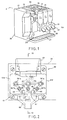
- Fig. 1 is a perspective view of a beverage dispensing unit including embodiments of the invention, in perspective, with a left door being open and cabinet top plate and a right door being removed;
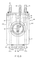
- Fig. 2 is a front view of a controlling unit included in the beverage dispensing unit of Fig. 1;
- Fig. 3 is a plan view of the controlling unit illustrated in Fig. 2;
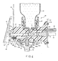
- Fig. 4 is a sectional view of the controlling unit taken along a line 10-10 in Fig. 2;
- Fig. 5 is a sectional view of the controlling unit taken along a line 11-11 in Fig. 2;
- Fig. 6 is a perspective view of an agitating member included in the controlling unit of Figs. 2 to 5;
- Fig. 7 is a side view of an operating member included in the beverage dispensing unit of Fig. 1; and
- Fig. 8 is a rear view of the operating member illustrated in Fig. 7.
- Fig. 1 shows a dispensing unit for dispensing a beverage and includes a
cabinet 20, a supplyingstation 21, and a dispensingportion 22. Thecabinet 20 is of a rectangular parallelopiped shape and has afront surface 23. The supplyingstation 21 is fixedly attached to a lower part of the front surface of thecabinet 20 and includes atray 24 for receiving thereon a cup (not shown). The dispensingportion 22 is placed over the supplyingstation 21 and is protruded from thefront surface 23 of thecabinet 20. - The dispensing
portion 22 is provided with a plurality of, for example three, operatingmembers 90. A combination of the dispensingportion 22 and at least one of the operatingmembers 90 is referred to as a controlling unit. - Referring to Figs. 2 to 5 in addition to Fig. 1, attention will be directed to the dispensing
portion 22. The dispensingportion 22 comprises a plurality of, for example, three controlling units. But only one of the controlling units is shown in the figure for simplification of the drawing and depicted at 60. The controllingunit 60 comprises abody 61 defined by front, rear, upper, bottom, left side, andright side surfaces body 61 defines syrup, original water,carbonated water paths frame 65 of thecabinet 20 by screws or the like. - The
syrup path 62 extends substantially in a vertical direction along a central portion of thebody 61 and has an inlet and an outlet opening which open at the upper and thebottom surfaces carbonated water paths syrup path 62, respectively. Each of the original and thecarbonated water paths bottom surfaces paths discharge tube 66 which is attached to abottom surface 61d of thebody 61. - The
body 61 is provided with asocket member 67 for detachably holding therein the syrup tank S1. Thesocket member 67 is detachably mounted on theupper surface 61c of thebody 61 and is changed dependent on a size of the syrup tank S1. The inlet opening of thesyrup path 62 is placed at an inside of thesocket member 67. - In the
body 61, agas path 68 is made to extend from therear surface 61b to the inside of thesocket member 67 as is best shown in Fig. 4 . Thegas path 68 is connected to theCO₂ gas cylinder 33 through apipe 69 and is for supplying another part of the CO₂ gas into the syrup tank S1 through acheck valve 71 in order to push out the syrup therefrom into thesyrup path 62. As a result, thesyrup path 62 serves to conduct the syrup as a beverage towards thedischarge tube 66. - The
original water path 63 is connected at the inlet opening thereof to thepipe 43 and serves to conduct the original water as the beverage towards thedischarge tube 66. - Similarly, the
carbonated water path 64 is connected at the inlet opening thereof to apipe 72 which is connected to thecarbonator 36. Thecarbonated water path 64 serves to conduct the carbonated water as the beverage towards thedischarge tube 66. - In Fig. 4 , the
body 61 has acylindrical hole 73 which communicates with thesyrup path 62 and which is open at therear surface 61b. Aclosing member 74 is screwed in thecylindrical hole 73. - The controlling
unit 60 further comprises avalve 75 placed in thecylindrical hole 73 for controlling open and close of thesyrup path 62. Thevalve 75 is forwardly urged by aspring 76 which is between thevalve 75 and theclosing member 74. As a result, thevalve 75 is in press contact with avalve seat 77 to close thesyrup path 62. In order to certainly close thesyrup path 62, aseal member 78 is mounted on thevalve 75. - The
valve 75 is fixedly connected to avalve rod 79 which is held by thebody 61 and is movable in the predetermined horizontal direction 39. Thevalve rod 79 has anend 79a which is forwardly projected from thefront surface 61a. When thevalve rod 79 is backwardly moved, thevalve 75 is displaced to open thesyrup path 62. - The
body 61 has an adjustinghole 81 which extends from thefront surface 61a to thesyrup path 62 in the predetermined horizontal direction 39. The adjustinghole 81 has an internal threadedportion 81a. - The controlling
unit 60 further comprises an adjustingmember 82 inserted into the adjustinghole 81. The adjustingmember 82 has anend portion 82a for adjusting a flow rate of the syrup in thesyrup path 62. Anotherend 82b of the adjustingmember 82 forwardly protrudes from thefront surface 61a of thebody 60. The adjustingmember 82 has an external threadedportion 82c which is screwed in the internal threaded portion 81b. - When the adjusting
member 82 is rotated by the use of a driving member or a screw driver (not shown), it is displaced in the predetermined horizontal direction. As a result, adjustment is carried out about the flow rate of the syrup in thesyrup path 62. - In Fig. 5 , the controlling
unit 60 is further provided with similar parts in connection with theoriginal water path 63 which are designated by like reference numerals added with dashes. A closing member 74' has a throughhole 83 which serves as a part of theoriginal water path 63. - When a valve rod 79' is backwardly moved, the valve 75' is displaced to open the
original water path 63. When the adjusting member 82' is rotated, it is displaced in the predetermined horizontal direction. As a result, control and adjustment are carried out about the original water in theoriginal water path 63. - Although description will be omitted, similar construction is provided in connection with the
carbonated water path 64. Therefore, similar control and adjustment are possible in connection with the carbonated water. - Mixing is carried out among the syrup, the original water, and the carbonated water in an interior of the
discharge tube 66. In order to favorably carry out the mixing, thedischarge tube 66 is provided with a mixingmember 83 in the interior thereof. - Referring to Fig. 6 , the mixing
member 83 comprises acylindrical member 84 and a ring-shapedplate 85 fixed onto an outer peripheral surface of thecylindrical member 84. Thecylindrical member 84 has acentral hole 84a and a plurality ofsmall side holes 84b extending from the outer peripheral surface of thecylindrical member 84 to thecentral hole 84a. Thecylindrical member 84 is connected to thebody 61 so that thecentral hole 84a communicates with thesyrup path 62. - The ring-shaped
plate 85 has a great number ofgrooves 85a in a peripheral surface thereof and is supported to ashoulder 66a formed on the inner peripheral surface of thedischarge tube 66. As a result, the ring-shapedplate 85 is placed under the outlet opening of each of the original and thecarbonated water paths plate 85 faces an innerperipheral surface 66b of thedischarge tube 66 to produce a guiding small hole therebetween for guiding the original and the carbonated water. - Returning to Figs. 2 through 5, the
body 61 is provided with twoarms 86 fixedly mounted on thefront surface 61a thereof for fixedly holding ashaft 87. Theshaft 87 has a pivot axis extending in an additional horizontal direction which intersects the first predetermined horizontal direction 39. - The
valve rods 79, 79', and 79'' are connected with one another through apin rod 88 in front of thefront surface 61a of thebody 61. - The controlling
unit 60 further comprises an operatingmember 90 which is operated by an operator or a user. Referring to Figs. 7 and 8 in addition to Fig. 4 , the operatingmember 90 comprises aplate portion 91, two attachingportions 92, and two hookingportions 93 as will presently be described. Theplate portion 91 has aback surface 91a placed to generally face thefront surface 61a of thebody 61. Therefore, theend portions 82b, 82'b, and 82''b of the adjustingmembers 82, 82', and 82'' are covered with theplate portion 91. - Each of the attaching
portions 92 is formed integral with theback surface 91a of theplate portion 91 and has an attachinggroove 92a for receiving both ends of theshaft 87 therein. The attachinggroove 92a is extended to permit movement of the operatingmember 90 in the first predetermined direction. A combination of thearms 86, theshaft 87, and the attachingportions 92 serves to pivotally support theplate portion 91 and may therefore be referred to as pivotally supporting means. - Each of the hooking
portions 93 is formed integral with theback surface 91a of theplate portion 91 and has a hookinggroove 93a for receiving thepin rod 88 therein to hook the hookingportion 91 with thepin rod 88. The hookinggroove 93a is extended so that the hooking portion is removable from the pin rod 99 with the operatingmember 90 moved upwardly. - When the
plate portion 91 is pushed rearwardly by an operator or a user, the operatingmember 90 is pivotally moved around theshaft 87. Responsive to operation of the operatingmember 90, thevalve rods 79, 79', and 79'' are moved rearwardly to open the syrup, the original water, thecarbonated water paths discharge tube 66 and then mixed with one another therein to produce a mixed beverage. The mixed beverage is discharged from thedischarge tube 66 into the cup. - If adjustment is desired about the flow rate of the syrup, the hooking
portions 93 are removed with the operatingmember 90 moved upwardly. Then, an upper part of theplate portion 91 is pulled forwardly so that the operatingmember 90 is pivotally moved downwardly around theshaft 87. As a result, theplate portion 91 does not cover theend portion 79a of the adjustingmember 79. In other words, theend portion 79a of the adjustingmember 79 are exposed ahead thebody 61. Therefore, the adjustingmember 79 can be readily operated to adjust the flow rate of the syrup through thesyrup path 61. - It is a matter of course that similar operation can be carried out about the flow rate of each of the original and the carbonated water
- While the present invention has thus far been described in connection with one preferred embodiments thereof, it will readily be possible for those skilled in the art to put this invention into practice in various other manners. For example, the shaft may be mounted to extend in the vertical direction.
Claims (3)
- A controlling unit for controlling the dispensing of a beverage, said unit including a body (61) in which is defined a path (62,63,64) for the beverage; valve means (75) for controlling flow along the path; valve operating means (79,91) including a control rod (79) which is displaceable along its axis to operate the valve means (75); an elongate member (82) which is displaceable along its axis for adjusting a flow rate of beverage in said beverage path; said valve operating means (79,91) further including a plate portion (91) which is pivotally mounted (86,87) to the body; characterised in that said body (61) has a principal surface (61a) which is intersected by the axes of the adjusting member (82) and the control rod (79), said control rod (79) having a portion (79a) projecting outwardly of said body surface (61a); and wherein said plate portion (91) generally overlies said body surface (61a) and the end of the adjusting member (82); said plate portion (91) having two flange portions (92,93) that project towards the body surface (61a); said body (61) having pivot means (86) projecting towards the plate portion (91) for said pivotal mounting thereof and including first pin means (87); said projection portion (79a) of the control rod (79) having second pin means (88), both said pin means (87,88) having axes extending mutually in parallel and intersecting respective flange portions (92,93); said flange portions having respective elongate slots (92a, 93a) in which the pin means engage; the slot (93a) in which the second pin means (88) engages having at one end an opening towards the body surface (61a); the elongation of the slots (92a, 93a) permitting the plate portion (91) to be displaced to bring the second pin means (88) adjacent the opening whereupon the plate portion can be pivoted about the first pin means (87) thus freeing itself from the second pin means (88); further pivoting exposing the end of the adjustment member (82) to permit adjustment thereof.
- A controlling unit as claimed in claim 1, said beverage path (62) extending in a first predetermined direction, wherein said body has a hole (81) extending from said principal surface (61a) to said beverage path in a second predetermined direction which intersects said first predetermined direction, said adjusting member (82) being inserted into said hole (81) to be movable in said second predetermined direction.
- A controlling unit as claimed in claim 2, wherein said hole (81) has an internal threaded portion, said adjusting (82) member having an external threaded portion (82c) which is screwed in said internal threaded portion (81a)
Applications Claiming Priority (4)
| Application Number | Priority Date | Filing Date | Title |
|---|---|---|---|
| JP37407/88 | 1988-02-22 | ||
| JP63037407A JPH01215336A (en) | 1988-02-22 | 1988-02-22 | Drink feeder using portable tank |
| JP43301/88 | 1988-02-27 | ||
| JP4330188A JPH01226588A (en) | 1988-02-27 | 1988-02-27 | Mixing valve unit for after mix soda drink distribution unit |
Publications (3)
| Publication Number | Publication Date |
|---|---|
| EP0338661A2 EP0338661A2 (en) | 1989-10-25 |
| EP0338661A3 EP0338661A3 (en) | 1990-02-21 |
| EP0338661B1 true EP0338661B1 (en) | 1993-08-18 |
Family
ID=26376533
Family Applications (1)
| Application Number | Title | Priority Date | Filing Date |
|---|---|---|---|
| EP89301689A Expired - Lifetime EP0338661B1 (en) | 1988-02-22 | 1989-02-22 | Dispensing control unit |
Country Status (4)
| Country | Link |
|---|---|
| US (1) | US4986448A (en) |
| EP (1) | EP0338661B1 (en) |
| KR (1) | KR890012885A (en) |
| DE (1) | DE68908455T2 (en) |
Cited By (1)
| Publication number | Priority date | Publication date | Assignee | Title |
|---|---|---|---|---|
| GB2637938A (en) * | 2024-02-07 | 2025-08-13 | Sas International Ltd | A tile assembly |
Families Citing this family (9)
| Publication number | Priority date | Publication date | Assignee | Title |
|---|---|---|---|---|
| US4982876A (en) * | 1986-02-10 | 1991-01-08 | Isoworth Limited | Carbonation apparatus |
| IT240441Y1 (en) * | 1996-02-09 | 2001-04-02 | Italtinto Srl | DOSING MACHINE IN PARTICULAR FOR DYES |
| FR2744996B1 (en) * | 1996-02-21 | 2000-01-21 | Vitop | REFRIGERANT CABINET FOR DISPENSING FOOD LIQUIDS |
| US6708741B1 (en) | 2000-08-24 | 2004-03-23 | Ocean Spray Cranberries, Inc. | Beverage dispenser |
| US7866508B2 (en) * | 2005-09-19 | 2011-01-11 | JMF Group LLC | Beverage dispensing system and method |
| USD603208S1 (en) * | 2008-08-29 | 2009-11-03 | Sunbeam Products, Inc. | Dispensing unit for beverage containers |
| USD622535S1 (en) * | 2009-11-30 | 2010-08-31 | Sunbeam Products, Inc. | Dispensing unit for a beverage container |
| WO2011074953A2 (en) * | 2009-12-16 | 2011-06-23 | Ipn Ip B.V. | Fluid dose-measuring device |
| CN203619242U (en) * | 2013-11-11 | 2014-06-04 | 李文钦 | Multifunctional water cup of water dispenser |
Family Cites Families (12)
| Publication number | Priority date | Publication date | Assignee | Title |
|---|---|---|---|---|
| DE423352C (en) * | 1924-11-13 | 1925-12-29 | Armaturenfabrik Thelen & Roden | Self-opening valve for tapping off carbonated fluids |
| US2776076A (en) * | 1955-11-01 | 1957-01-01 | Leslie R Nunn | Cooler-dispenser with removable and refillable container |
| US3584762A (en) * | 1968-12-04 | 1971-06-15 | Golconda Corp | Root beer postmix drink dispenser |
| DE1814695B1 (en) * | 1968-12-14 | 1970-07-02 | Tornado Gmbh | Tap for carbonated mixed drinks |
| US3800826A (en) * | 1972-12-26 | 1974-04-02 | Mc Cann S Eng & Mfg Co | Soft drink dispenser disconnect assembly |
| US4357972A (en) * | 1980-01-17 | 1982-11-09 | Standard-Keil Hardware Manufacturing Company, A Division Of Buildex Incorporated | Water glass filler |
| US4688701A (en) * | 1981-06-26 | 1987-08-25 | The Coca-Cola Company | Self-contained portable post-mix beverage dispenser apparatus having access for manually loading syrup CO2 and water |
| US4493441A (en) * | 1981-11-12 | 1985-01-15 | The Coca-Cola Company | Portable post-mix beverage dispenser unit |
| IT1177208B (en) * | 1983-11-16 | 1987-08-26 | Coca Cola Co | DISTRIBUTOE OF DRINKS |
| US4635824A (en) * | 1985-09-13 | 1987-01-13 | The Coca-Cola Company | Low-cost post-mix beverage dispenser and syrup supply system therefor |
| US4699188A (en) * | 1986-01-17 | 1987-10-13 | Baker Henry E | Hygienic liquid dispensing system |
| US4703870A (en) * | 1986-07-21 | 1987-11-03 | The Cocoa-Cola Company | Water reservoir assembly for post-mix beverage dispenser |
-
1989
- 1989-02-22 US US07/313,504 patent/US4986448A/en not_active Expired - Fee Related
- 1989-02-22 DE DE89301689T patent/DE68908455T2/en not_active Expired - Fee Related
- 1989-02-22 EP EP89301689A patent/EP0338661B1/en not_active Expired - Lifetime
- 1989-02-22 KR KR1019890002067A patent/KR890012885A/en not_active Ceased
Cited By (1)
| Publication number | Priority date | Publication date | Assignee | Title |
|---|---|---|---|---|
| GB2637938A (en) * | 2024-02-07 | 2025-08-13 | Sas International Ltd | A tile assembly |
Also Published As
| Publication number | Publication date |
|---|---|
| EP0338661A2 (en) | 1989-10-25 |
| DE68908455D1 (en) | 1993-09-23 |
| DE68908455T2 (en) | 1994-03-03 |
| EP0338661A3 (en) | 1990-02-21 |
| KR890012885A (en) | 1989-09-19 |
| US4986448A (en) | 1991-01-22 |
Similar Documents
| Publication | Publication Date | Title |
|---|---|---|
| US5097989A (en) | Beverage mixing and dispensing apparatus | |
| US5297400A (en) | Liquid dispensing assembly for a refrigerator | |
| US5265772A (en) | Dispensing apparatus with tube locator | |
| US4306667A (en) | Post-mix beverage dispensing system syrup package, valving system, and carbonator therefor | |
| JPH036076B2 (en) | ||
| JP3366005B2 (en) | Valve actuator for soft drink dispensing station | |
| US7815077B2 (en) | Soap dispensing apparatus | |
| EP0358360A1 (en) | Removable syrup package | |
| EP0250003A1 (en) | Beverage dispenser | |
| EP0226437A2 (en) | Beverage dispenser valve | |
| EP0351031A2 (en) | Water reservoir assembly for a post-mix beverage dispenser | |
| EP0059533B1 (en) | Aerated drinks machine | |
| EP0410940B1 (en) | Backpack spraying equipment | |
| US4986448A (en) | Beverage dispensing unit with a control unit for controlling dispensation of a beverage | |
| EP0336730B1 (en) | Beverage dispensing unit | |
| GB2093359A (en) | Carbonated drinks machine | |
| EP0073099B1 (en) | Appliance for making an aerated beverage | |
| EP0050465A1 (en) | A height control mechanism for a chair, table or the like | |
| US5014886A (en) | Dispensing valve | |
| GB2093358A (en) | Carbonated drinks machine | |
| US7882705B2 (en) | Water cooler | |
| JP4525369B2 (en) | Beverage dispenser | |
| US20070062975A1 (en) | Soap dispensing apparatus | |
| GB2230252A (en) | A multi-flavour drink dispenser | |
| WO2023238554A1 (en) | Beverage dispensing device and beverage server provided with same |
Legal Events
| Date | Code | Title | Description |
|---|---|---|---|
| PUAI | Public reference made under article 153(3) epc to a published international application that has entered the european phase |
Free format text: ORIGINAL CODE: 0009012 |
|
| AK | Designated contracting states |
Kind code of ref document: A2 Designated state(s): DE GB IT |
|
| PUAL | Search report despatched |
Free format text: ORIGINAL CODE: 0009013 |
|
| AK | Designated contracting states |
Kind code of ref document: A3 Designated state(s): DE GB IT |
|
| 17P | Request for examination filed |
Effective date: 19900528 |
|
| 17Q | First examination report despatched |
Effective date: 19910801 |
|
| RAP1 | Party data changed (applicant data changed or rights of an application transferred) |
Owner name: KIRIN BEVERAGE CORPORATION Owner name: SANDEN CORPORATION |
|
| GRAA | (expected) grant |
Free format text: ORIGINAL CODE: 0009210 |
|
| AK | Designated contracting states |
Kind code of ref document: B1 Designated state(s): DE GB IT |
|
| REF | Corresponds to: |
Ref document number: 68908455 Country of ref document: DE Date of ref document: 19930923 |
|
| ITF | It: translation for a ep patent filed | ||
| PLBE | No opposition filed within time limit |
Free format text: ORIGINAL CODE: 0009261 |
|
| STAA | Information on the status of an ep patent application or granted ep patent |
Free format text: STATUS: NO OPPOSITION FILED WITHIN TIME LIMIT |
|
| 26N | No opposition filed | ||
| PGFP | Annual fee paid to national office [announced via postgrant information from national office to epo] |
Ref country code: GB Payment date: 19950214 Year of fee payment: 7 |
|
| PGFP | Annual fee paid to national office [announced via postgrant information from national office to epo] |
Ref country code: DE Payment date: 19950222 Year of fee payment: 7 |
|
| PG25 | Lapsed in a contracting state [announced via postgrant information from national office to epo] |
Ref country code: GB Effective date: 19960222 |
|
| GBPC | Gb: european patent ceased through non-payment of renewal fee |
Effective date: 19960222 |
|
| PG25 | Lapsed in a contracting state [announced via postgrant information from national office to epo] |
Ref country code: DE Effective date: 19961101 |
|
| PG25 | Lapsed in a contracting state [announced via postgrant information from national office to epo] |
Ref country code: IT Free format text: LAPSE BECAUSE OF NON-PAYMENT OF DUE FEES Effective date: 20050222 |