EP0338154B1 - Submerged actuator - Google Patents
Submerged actuator Download PDFInfo
- Publication number
- EP0338154B1 EP0338154B1 EP88303674A EP88303674A EP0338154B1 EP 0338154 B1 EP0338154 B1 EP 0338154B1 EP 88303674 A EP88303674 A EP 88303674A EP 88303674 A EP88303674 A EP 88303674A EP 0338154 B1 EP0338154 B1 EP 0338154B1
- Authority
- EP
- European Patent Office
- Prior art keywords
- tieback
- shoulder
- sleeve
- housing
- actuator sleeve
- Prior art date
- Legal status (The legal status is an assumption and is not a legal conclusion. Google has not performed a legal analysis and makes no representation as to the accuracy of the status listed.)
- Expired
Links
Images
Classifications
-
- E—FIXED CONSTRUCTIONS
- E21—EARTH OR ROCK DRILLING; MINING
- E21B—EARTH OR ROCK DRILLING; OBTAINING OIL, GAS, WATER, SOLUBLE OR MELTABLE MATERIALS OR A SLURRY OF MINERALS FROM WELLS
- E21B23/00—Apparatus for displacing, setting, locking, releasing or removing tools, packers or the like in boreholes or wells
- E21B23/02—Apparatus for displacing, setting, locking, releasing or removing tools, packers or the like in boreholes or wells for locking the tools or the like in landing nipples or in recesses between adjacent sections of tubing
-
- F—MECHANICAL ENGINEERING; LIGHTING; HEATING; WEAPONS; BLASTING
- F16—ENGINEERING ELEMENTS AND UNITS; GENERAL MEASURES FOR PRODUCING AND MAINTAINING EFFECTIVE FUNCTIONING OF MACHINES OR INSTALLATIONS; THERMAL INSULATION IN GENERAL
- F16L—PIPES; JOINTS OR FITTINGS FOR PIPES; SUPPORTS FOR PIPES, CABLES OR PROTECTIVE TUBING; MEANS FOR THERMAL INSULATION IN GENERAL
- F16L37/00—Couplings of the quick-acting type
- F16L37/002—Couplings of the quick-acting type which can be controlled at a distance
-
- Y—GENERAL TAGGING OF NEW TECHNOLOGICAL DEVELOPMENTS; GENERAL TAGGING OF CROSS-SECTIONAL TECHNOLOGIES SPANNING OVER SEVERAL SECTIONS OF THE IPC; TECHNICAL SUBJECTS COVERED BY FORMER USPC CROSS-REFERENCE ART COLLECTIONS [XRACs] AND DIGESTS
- Y10—TECHNICAL SUBJECTS COVERED BY FORMER USPC
- Y10S—TECHNICAL SUBJECTS COVERED BY FORMER USPC CROSS-REFERENCE ART COLLECTIONS [XRACs] AND DIGESTS
- Y10S285/00—Pipe joints or couplings
- Y10S285/91—Gaskets
Definitions
- the present invention relates to an improved sleeve actuator in which the cavity between the sleeve and the tubular member with which it coacts excludes the well liquids from entry therein so that hydraulic lock does not prevent proper operation.
- U. S. Patent No. 4,662,663 discloses a method and apparatus for the forming of one tubular member of a subsea pipeline into another tubular member having internal lands and grooves for receiving the formed member and provides for the filling of the grooves with a structure which compensates for the pressure which tends to build during the forming step.
- This patent suggests the use of a gas filled tube or the use of a material which is composed of a plurality of microspheres in an epoxy matrix. This material is described in such patent as being suitable to exclude sufficient liquid (sea water) from the grooves so that when the inner tubular member is formed therein that the material collapses to prevent any pressure build-up in the grooves which would interfere with the proper completion of the forming step.
- US-A-4076278 describes a flowline connector which has a tubular housing and a mandrel movable axially within the housing.
- the mandrel can be locked in position within the housing by means of locking dogs which can be wedged into a recess in the tubular housing by means of an actuator sleeve.
- a well structure comprising a tubular well housing with an internal latching recess and an upwardly facing shoulder above said recess, a tieback adapted to be landed on said housing shoulder and having an upper internal surface, a lower internal surface of smaller diameter than said upper internal surface and an upwardly facing internal shoulder between said upper and lower surfaces, an actuator sleeve having an upper outer surface fitting closely within the interior of said tieback upper internal surface, latching elements having an integral upper surface tapering downwardly and inwardly and carried by said tieback, and a tapered surface on the lower outer portion of said actuator sleeve arranged to mate with the tapered surface on said latch elements so that movement of the actuator sleeve downwardly within said well housing wedges said latch elements into said housing internal recess to secure said tieback within said housing, and characterised in that said actuator sleeve has a lower outer surface with a smaller diameter than that of said upper outer surface and fitting closely within the interior of said tieback lower internal surface, a shoulder being
- the present invention provides an actuator for coaction with a tubular member and a movable element which is not prevented from proper actuation by the influx of liquids into the space between the actuator and the tubular member.
- Well structure 10 illustrated in the drawings includes first tubular member or housing 12, second tubular member or tieback 14, and sleeve actuator 16 positioned therein to actuate the locking element, such as latch elements or dogs 18 supported in windows in the lower end of tieback 14 as shown.
- Sleeve actuator 16 is shown supported on running tool 20 with tieback 14 carried thereby.
- the assembly is lowered within housing on running string 22.
- Tieback 14 landed on the upper end of housing 12 and its windows carrying latch elements 18 are positioned within the interior of housing 12 as shown in FIGURE 1.
- Downwardly facing external shoulder 24 on tieback 14 seats on upwardly facing shoulder 26 of housing 12.
- Internal surface 28 of housing 12 includes latching recess 30 which is positioned to receive latch elements 18.
- Seal 32 is positioned within groove 34 on the exterior of tieback 14 below shoulder 24 and, as shown in the figures, seals against the internal surface 28 of housing 12 when tieback 14 is properly positioned therein.
- Windows 36 extend through the lower end of tieback 14.
- Sleeve actuator 16 and tieback 14 are lowered within housing 12 to the position shown in FIGURE 1 on running tool 20 which is supported on running string 22.
- Sleeve actuator 16 is sized to be positioned within tieback 14 and housing 12 as shown with seal 38 positioned within groove 40 on the exterior upper surface 42 above downwardly facing shoulder 44. Seal 38 engages inner surface 46 of tieback 14.
- Surface 48 on the exterior of sleeve actuator 16 below shoulder 44 includes groove 50 in which seal ring 52 is positioned for sealing against tieback inner surface 54 below tieback shoulder 56 which faces upwardly.
- Volume compensating material ring 58 is positioned in surrounding relationship to sleeve 16 below shoulder 44. Material ring 58 is provided to have an outer diameter either the same or slightly smaller than the diameter of surface 42 so that it will readily enter within surface 46 of tieback 14.
- Any suitable volume compensating material 60 may be used for ring 58 provided it excludes liquids from the annular space 62 between shoulders 44 and 56 and between surfaces 46 and 48 and has the ability to collapse under actuating pressure to allow full movement of actuator sleeve 16 to set latch elements into housing recess 30.
- a suitable material is microspheres embedded in an epoxy matrix. The function of the pressure compensating material is to exclude the liquids from the annular space 62 without collapsing but to collapse when force above the local environment is applied to create the movement of actuator sleeve 16. Material 60 thus prevents the creation of a hydraulic lock without itself creating any appreciable resistance to the actuation of sleeve actuator 16.
- Latch elements 18 are carried in windows 36 in the lower end of tieback with cam surface 64 on the exterior of sleeve 16 mating with upper inner cam surfaces 66 on elements 18.
- Split ring 68 engages in groove 70 in the lower portion of sleeve 16 to support latch elements 18 in position for actuation.
- Sleeve 16 is supported on the exterior of running tool 20 by a plurality of spring loaded retaining pins 72 which are positioned within recesses in the lower exterior of tool 20.
- the outer ends of pins 72 have a frustoconical shape which mates with the inner tapered surface 74 on the lower end of sleeve 16.
- Sleeve 16 is positioned around the exterior of tool 20 between pins 72 and upper running tool flange 76.
- Seal ring 78 is positioned within groove 80 around the exterior of the lower portion to running tool 20 and seals against interior surface 82 of sleeve 16.
- sleeve 16 With sleeve 16 positioned as shown in FIGURE 1, it is in position to be actuated to force latch elements 18 into engagement with the interior recess 30 of housing 12. Pressure is applied around the exterior of running string 22 above running tool 20. This pressure is sufficient to cause sleeve to be moved downwardly into the position shown in FIGURE 2. Sleeve 16 is subjected to a pressure differential because of seal rings 78 and 38. The downward movement of sleeve 16 causes volume compensating material ring 58 to collapse as the annular space in which it is positioned is reduced in volume by this downward movement of sleeve 16.
- Latch elements 18 engage the lower portion of their windows 36 in tieback 14 and the mating cam surfaces 64 and 66 on sleeve 16 and latch elements 18 coact to cause latch elements 18 to move outwardly into latching engagement within recess 30.
- the downward movement of sleeve 16 also causes pins 72 to be cammed inwardly into their recesses so that tool 20 may be retrieved from within sleeve 16 upon completion of the setting of latch elements 18.
Landscapes
- Engineering & Computer Science (AREA)
- Mining & Mineral Resources (AREA)
- Geology (AREA)
- General Engineering & Computer Science (AREA)
- Life Sciences & Earth Sciences (AREA)
- Environmental & Geological Engineering (AREA)
- Fluid Mechanics (AREA)
- Mechanical Engineering (AREA)
- General Life Sciences & Earth Sciences (AREA)
- Geochemistry & Mineralogy (AREA)
- Physics & Mathematics (AREA)
- Actuator (AREA)
- Aeration Devices For Treatment Of Activated Polluted Sludge (AREA)
- Centrifugal Separators (AREA)
- Catching Or Destruction (AREA)
- Motor Or Generator Frames (AREA)
Abstract
Description
- In petroleum wells, sliding piston sleeve actuators are often used for many purposes. In such wells it is important that pockets, created in the annular spaces between the sleeves and the tubular members with which they coact, not be filled with liquid which would result in a hydraulic lock preventing proper operation of the moving sleeve. The present invention relates to an improved sleeve actuator in which the cavity between the sleeve and the tubular member with which it coacts excludes the well liquids from entry therein so that hydraulic lock does not prevent proper operation.
- U. S. Patent No. 4,662,663 discloses a method and apparatus for the forming of one tubular member of a subsea pipeline into another tubular member having internal lands and grooves for receiving the formed member and provides for the filling of the grooves with a structure which compensates for the pressure which tends to build during the forming step. This patent suggests the use of a gas filled tube or the use of a material which is composed of a plurality of microspheres in an epoxy matrix. This material is described in such patent as being suitable to exclude sufficient liquid (sea water) from the grooves so that when the inner tubular member is formed therein that the material collapses to prevent any pressure build-up in the grooves which would interfere with the proper completion of the forming step.
- US-A-4076278 describes a flowline connector which has a tubular housing and a mandrel movable axially within the housing. The mandrel can be locked in position within the housing by means of locking dogs which can be wedged into a recess in the tubular housing by means of an actuator sleeve.
- According to the present invention there is provided a well structure comprising
a tubular well housing with an internal latching recess and an upwardly facing shoulder above said recess,
a tieback adapted to be landed on said housing shoulder and having an upper internal surface, a lower internal surface of smaller diameter than said upper internal surface and an upwardly facing internal shoulder between said upper and lower surfaces,
an actuator sleeve having an upper outer surface fitting closely within the interior of said tieback upper internal surface,
latching elements having an integral upper surface tapering downwardly and inwardly and carried by said tieback, and
a tapered surface on the lower outer portion of said actuator sleeve arranged to mate with the tapered surface on said latch elements so that movement of the actuator sleeve downwardly within said well housing wedges said latch elements into said housing internal recess to secure said tieback within said housing, and characterised in that
said actuator sleeve has a lower outer surface with a smaller diameter than that of said upper outer surface and fitting closely within the interior of said tieback lower internal surface, a shoulder being formed between said upper and lower portions facing said tieback shoulder, and
collapsible pressure compensating material substantially filling the volume of the annular space between the tieback shoulder and the sleeve shoulder at its maximum point thereby excluding liquids from said annular space, the arrangement being such that upon said relative movement of said first member and said actuator body shoulders toward each other said material collapses thereby decreasing in volume as said annular space decreases in volume. - The present invention provides an actuator for coaction with a tubular member and a movable element which is not prevented from proper actuation by the influx of liquids into the space between the actuator and the tubular member.
- The invention will be described now by way of example only, with particular reference to the accompanying drawings. In the drawings"
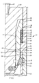
- FIGURE 1 is a partial sectional view of an actuator sleeve within a well housing having a tieback landed therein wherein the sleeve is moved axially responsive to pressure and actuates the latch elements to secure the tieback to the housing.
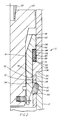
- FIGURE 2 is similar to FIGURE 1 and shows the actuator in its set position to illustrate the collapse of the pressure compensating material.
- Well structure 10 illustrated in the drawings includes first tubular member or
housing 12, second tubular member ortieback 14, andsleeve actuator 16 positioned therein to actuate the locking element, such as latch elements ordogs 18 supported in windows in the lower end oftieback 14 as shown.Sleeve actuator 16 is shown supported on runningtool 20 withtieback 14 carried thereby. The assembly is lowered within housing on runningstring 22.Tieback 14 landed on the upper end ofhousing 12 and its windows carryinglatch elements 18 are positioned within the interior ofhousing 12 as shown in FIGURE 1. Downwardly facingexternal shoulder 24 ontieback 14 seats on upwardly facingshoulder 26 ofhousing 12.Internal surface 28 ofhousing 12 includeslatching recess 30 which is positioned to receivelatch elements 18.Seal 32 is positioned withingroove 34 on the exterior oftieback 14 belowshoulder 24 and, as shown in the figures, seals against theinternal surface 28 ofhousing 12 whentieback 14 is properly positioned therein. Windows 36 extend through the lower end oftieback 14. -
Sleeve actuator 16 andtieback 14 are lowered withinhousing 12 to the position shown in FIGURE 1 on runningtool 20 which is supported on runningstring 22.Sleeve actuator 16 is sized to be positioned withintieback 14 andhousing 12 as shown withseal 38 positioned withingroove 40 on the exteriorupper surface 42 above downwardly facingshoulder 44. Seal 38 engagesinner surface 46 oftieback 14.Surface 48 on the exterior ofsleeve actuator 16 belowshoulder 44 includesgroove 50 in whichseal ring 52 is positioned for sealing against tiebackinner surface 54 belowtieback shoulder 56 which faces upwardly. Volume compensatingmaterial ring 58 is positioned in surrounding relationship tosleeve 16 belowshoulder 44.Material ring 58 is provided to have an outer diameter either the same or slightly smaller than the diameter ofsurface 42 so that it will readily enter withinsurface 46 oftieback 14. Any suitablevolume compensating material 60 may be used forring 58 provided it excludes liquids from theannular space 62 betweenshoulders surfaces actuator sleeve 16 to set latch elements intohousing recess 30. A suitable material is microspheres embedded in an epoxy matrix. The function of the pressure compensating material is to exclude the liquids from theannular space 62 without collapsing but to collapse when force above the local environment is applied to create the movement ofactuator sleeve 16.Material 60 thus prevents the creation of a hydraulic lock without itself creating any appreciable resistance to the actuation ofsleeve actuator 16. -
Latch elements 18 are carried inwindows 36 in the lower end of tieback with cam surface 64 on the exterior ofsleeve 16 mating with upper inner cam surfaces 66 onelements 18. Split ring 68 engages in groove 70 in the lower portion ofsleeve 16 to supportlatch elements 18 in position for actuation. - Sleeve 16 is supported on the exterior of running
tool 20 by a plurality of spring loaded retaining pins 72 which are positioned within recesses in the lower exterior oftool 20. The outer ends of pins 72 have a frustoconical shape which mates with the inner tapered surface 74 on the lower end ofsleeve 16. Sleeve 16 is positioned around the exterior oftool 20 between pins 72 and upper running tool flange 76. Seal ring 78 is positioned within groove 80 around the exterior of the lower portion to runningtool 20 and seals against interior surface 82 ofsleeve 16. - With
sleeve 16 positioned as shown in FIGURE 1, it is in position to be actuated to forcelatch elements 18 into engagement with theinterior recess 30 ofhousing 12. Pressure is applied around the exterior of runningstring 22 above runningtool 20. This pressure is sufficient to cause sleeve to be moved downwardly into the position shown in FIGURE 2.Sleeve 16 is subjected to a pressure differential because ofseal rings 78 and 38. The downward movement ofsleeve 16 causes volume compensatingmaterial ring 58 to collapse as the annular space in which it is positioned is reduced in volume by this downward movement ofsleeve 16.Latch elements 18 engage the lower portion of theirwindows 36 intieback 14 and the mating cam surfaces 64 and 66 onsleeve 16 andlatch elements 18 coact to causelatch elements 18 to move outwardly into latching engagement withinrecess 30. The downward movement ofsleeve 16 also causes pins 72 to be cammed inwardly into their recesses so thattool 20 may be retrieved from withinsleeve 16 upon completion of the setting oflatch elements 18.
Claims (4)
- A well structure (10) comprising
a tubular well housing (12) with an internal latching recess (30) and an upwardly facing shoulder (26) above said recess (30),
a tieback (14) adapted to be landed on said housing shoulder (26) and having an upper internal surface (46), a lower internal surface (54) of smaller diameter than said upper internal surface (46) and an upwardly facing internal shoulder (56) between said upper and lower surfaces (46, 54),
an actuator sleeve (16) having an upper outer surface (42) fitting closely within the interior of said tieback upper internal surface (46),
latching elements (18) having an integral upper surface tapering downwardly and inwardly and carried by said tieback (14), and
a tapered surface on the lower outer portion of said actuator sleeve (16) arranged to mate with the tapered surface on said latch elements (18) so that movement of the actuator sleeve (16) downwardly within said well housing (12) wedges said latch elements (18) into said housing internal recess (30) to secure said tieback (14) within said housing (12), and characterised in that
said actuator sleeve (16) has a lower outer surface (48) with a smaller diameter than that of said upper outer surface (42) and fitting closely within the interior of said tieback lower internal surface (54), a shoulder (44) being formed between said upper and lower portions facing said tieback shoulder (56), and
collapsible pressure compensating material (60) substantially filling the volume of the annular space (62) between the tieback shoulder (56) and the sleeve shoulder (44) at its maximum point thereby excluding liquids from said annular space (62), the arrangement being such that upon said relative movement of said first member and said actuator body shoulders (44, 56) toward each other said material (60) collapses thereby decreasing in volume as said annular space (62) decreases in volume. - A well structure (10) according to claim 1 including
means for supporting said latch elements (18) and said tieback (14) on said actuator sleeve (16) exterior below said lower tapered surface during running into the well housing (12). - A well structure (10) according to claim 1 or claim 2, including
means (38) for sealing between the upper outer surface (42) of said actuating sleeve (16) and the upper internal surface (46) of said tieback (14), and
means (52) for sealing between the lower outer surface (48) of said actuating sleeve (16) above said lower tapered surface and the lower internal surface of said tieback (14) whereby pressure exerted above said actuator sleeve (16) exerts a downward force on said actuator sleeve (16) to move it downwardly within said tieback 914) moving said latch elements (18) into latching engagement within said recess (30). - A well structure (10) according to any one of claims 1 to 3, including
a running tool (20) for lowering said actuator sleeve (16), said tieback (14) and said latch elements (18) into said well housing (12),
said running tool (20) including means for supporting said actuator sleeve (16) on its exterior and means for connecting to a running string (22).
Priority Applications (8)
| Application Number | Priority Date | Filing Date | Title |
|---|---|---|---|
| EP88303674A EP0338154B1 (en) | 1988-04-22 | 1988-04-22 | Submerged actuator |
| AT88303674T ATE84116T1 (en) | 1988-04-22 | 1988-04-22 | SUBMERGED ACTUATION MECHANISM. |
| DE8888303674T DE3877185T2 (en) | 1988-04-22 | 1988-04-22 | SUBMERSIBLE ACTUATION MECHANISM. |
| US07/193,068 US4869535A (en) | 1988-04-22 | 1988-05-12 | Submerged actuator |
| CA000582431A CA1317874C (en) | 1988-04-22 | 1988-11-07 | Submerged actuator |
| JP28354688A JPH01271598A (en) | 1988-04-22 | 1988-11-09 | Well structure |
| NO89891645A NO891645L (en) | 1988-04-22 | 1989-04-21 | BRIDGE CONSTRUCTION. |
| BR898901901A BR8901901A (en) | 1988-04-22 | 1989-04-21 | POCO STRUCTURE |
Applications Claiming Priority (1)
| Application Number | Priority Date | Filing Date | Title |
|---|---|---|---|
| EP88303674A EP0338154B1 (en) | 1988-04-22 | 1988-04-22 | Submerged actuator |
Publications (2)
| Publication Number | Publication Date |
|---|---|
| EP0338154A1 EP0338154A1 (en) | 1989-10-25 |
| EP0338154B1 true EP0338154B1 (en) | 1992-12-30 |
Family
ID=8200043
Family Applications (1)
| Application Number | Title | Priority Date | Filing Date |
|---|---|---|---|
| EP88303674A Expired EP0338154B1 (en) | 1988-04-22 | 1988-04-22 | Submerged actuator |
Country Status (4)
| Country | Link |
|---|---|
| US (1) | US4869535A (en) |
| EP (1) | EP0338154B1 (en) |
| AT (1) | ATE84116T1 (en) |
| DE (1) | DE3877185T2 (en) |
Families Citing this family (11)
| Publication number | Priority date | Publication date | Assignee | Title |
|---|---|---|---|---|
| US5038865A (en) * | 1989-12-29 | 1991-08-13 | Cooper Industries, Inc. | Method of and apparatus for protecting downhole equipment |
| US7377323B2 (en) * | 2005-01-20 | 2008-05-27 | Cameron International Corporation | Blowout preventer stack landing assist tool |
| US7234528B2 (en) * | 2005-03-04 | 2007-06-26 | Vetco Gray Inc. | Multi-purpose sleeve for tieback connector |
| WO2009134902A1 (en) * | 2008-04-30 | 2009-11-05 | Altarock Energy, Inc. | System and method for use of pressure actuated collapsing capsules suspended in a thermally expanding fluid in a subterranean containment space |
| WO2009135069A1 (en) | 2008-04-30 | 2009-11-05 | Altarock Energy, Inc. | Method and cooling system for electric submersible pumps/motors for use in geothermal wells |
| WO2009135073A2 (en) | 2008-04-30 | 2009-11-05 | Altarock Energy, Inc. | System and method for aquifer geo-cooling |
| US8272437B2 (en) | 2008-07-07 | 2012-09-25 | Altarock Energy, Inc. | Enhanced geothermal systems and reservoir optimization |
| US8091639B2 (en) | 2008-08-20 | 2012-01-10 | University Of Utah Research Foundation | Geothermal well diversion agent formed from in situ decomposition of carbonyls at high temperature |
| WO2010144872A1 (en) | 2009-06-12 | 2010-12-16 | Altarock Energy, Inc. | An injection-backflow technique for measuring fracture surface area adjacent to a wellbore |
| US9151125B2 (en) | 2009-07-16 | 2015-10-06 | Altarock Energy, Inc. | Temporary fluid diversion agents for use in geothermal well applications |
| WO2011047096A1 (en) | 2009-10-14 | 2011-04-21 | Altarock Energy, Inc. | In situ decomposition of carbonyls at high temperature for fixing incomplete and failed well seals |
Family Cites Families (10)
| Publication number | Priority date | Publication date | Assignee | Title |
|---|---|---|---|---|
| US3163223A (en) * | 1961-07-26 | 1964-12-29 | Shell Oil Co | Wellhead connector |
| US3393926A (en) * | 1965-09-09 | 1968-07-23 | James F. Arnold | Hydraulic coupling |
| US3510153A (en) * | 1968-10-14 | 1970-05-05 | Shaffer Tool Works | Universal connecting joint |
| FR2316522A1 (en) * | 1975-06-30 | 1977-01-28 | Erap | CONNECTION DEVICE FOR SUCCESSIVE PORTIONS OF PIPES, ESPECIALLY FOR SUBMERSIBLE OIL PIPES |
| US4049297A (en) * | 1975-12-15 | 1977-09-20 | Reneau Bobby J | Pipe coupling apparatus |
| US4076278A (en) * | 1977-01-27 | 1978-02-28 | Societe Nationale Elf Aquitaine (Production) | Laterally engageable flowline connector device |
| US4453745A (en) * | 1981-08-17 | 1984-06-12 | Nelson Norman A | Lockdown mechanism for wellhead connector |
| US4662663A (en) * | 1983-12-19 | 1987-05-05 | Cameron Iron Works, Inc. | Tubular member for underwater connection having volume |
| FR2579291B1 (en) * | 1985-03-22 | 1987-05-07 | Alsthom Atlantique | DEVICE FOR SEALED CONNECTION OF TWO SECTIONS OF A FLUID CONDUIT |
| US4696493A (en) * | 1986-06-11 | 1987-09-29 | Vetco-Gray Inc. | Subsea wellhead tieback system |
-
1988
- 1988-04-22 AT AT88303674T patent/ATE84116T1/en not_active IP Right Cessation
- 1988-04-22 DE DE8888303674T patent/DE3877185T2/en not_active Expired - Fee Related
- 1988-04-22 EP EP88303674A patent/EP0338154B1/en not_active Expired
- 1988-05-12 US US07/193,068 patent/US4869535A/en not_active Expired - Fee Related
Also Published As
| Publication number | Publication date |
|---|---|
| DE3877185D1 (en) | 1993-02-11 |
| US4869535A (en) | 1989-09-26 |
| EP0338154A1 (en) | 1989-10-25 |
| DE3877185T2 (en) | 1993-05-06 |
| ATE84116T1 (en) | 1993-01-15 |
Similar Documents
| Publication | Publication Date | Title |
|---|---|---|
| EP0289104B1 (en) | Annular wellhead seal | |
| US4508167A (en) | Selective casing bore receptacle | |
| EP0289107B1 (en) | Wellhead seal assembly | |
| EP0329895B1 (en) | Hanger and seal assembly | |
| EP0715056B1 (en) | Blanking plug assembly | |
| US4469172A (en) | Self-energizing locking mechanism | |
| US5372201A (en) | Annulus pressure actuated casing hanger running tool | |
| US5535827A (en) | Hydraulic connector | |
| AU600180B2 (en) | Running tool | |
| US4519633A (en) | Subsea well casing tieback connector | |
| GB2251012A (en) | Metal-to-metal annulus packoff | |
| US3933202A (en) | Apparatus for setting and locking packing assemblies in wellheads | |
| EP0275612A1 (en) | Well packer inflation system and method of inflating same | |
| US4406324A (en) | Bottom lock pipe seal assembly | |
| EP0495437B1 (en) | Hydraulic packoff and casing hanger installation tool | |
| GB2176518A (en) | Wellhead equipment | |
| GB2089866A (en) | Underwater christmas tree cap and lockdown apparatus | |
| EP0146316B1 (en) | Mehtod of joining pipe | |
| US4869535A (en) | Submerged actuator | |
| US4513817A (en) | Casing bore receptacle | |
| GB2150173A (en) | Torque multiplier subsea tool | |
| GB2268990A (en) | Tieback connector,locking device and running tool | |
| GB2272033A (en) | Contingency tieback connector | |
| US6609731B2 (en) | Connector | |
| US4844511A (en) | Tubular connector |
Legal Events
| Date | Code | Title | Description |
|---|---|---|---|
| PUAI | Public reference made under article 153(3) epc to a published international application that has entered the european phase |
Free format text: ORIGINAL CODE: 0009012 |
|
| AK | Designated contracting states |
Kind code of ref document: A1 Designated state(s): AT DE FR GB NL |
|
| RAP1 | Party data changed (applicant data changed or rights of an application transferred) |
Owner name: CAMERON IRON WORKS USA, INC. (A DELAWARE CORP.) |
|
| 17P | Request for examination filed |
Effective date: 19900329 |
|
| RAP1 | Party data changed (applicant data changed or rights of an application transferred) |
Owner name: COOPER INDUSTRIES INC. |
|
| 17Q | First examination report despatched |
Effective date: 19910904 |
|
| GRAA | (expected) grant |
Free format text: ORIGINAL CODE: 0009210 |
|
| AK | Designated contracting states |
Kind code of ref document: B1 Designated state(s): AT DE FR GB NL |
|
| REF | Corresponds to: |
Ref document number: 84116 Country of ref document: AT Date of ref document: 19930115 Kind code of ref document: T |
|
| REF | Corresponds to: |
Ref document number: 3877185 Country of ref document: DE Date of ref document: 19930211 |
|
| ET | Fr: translation filed | ||
| PGFP | Annual fee paid to national office [announced via postgrant information from national office to epo] |
Ref country code: NL Payment date: 19930430 Year of fee payment: 6 |
|
| PLBE | No opposition filed within time limit |
Free format text: ORIGINAL CODE: 0009261 |
|
| STAA | Information on the status of an ep patent application or granted ep patent |
Free format text: STATUS: NO OPPOSITION FILED WITHIN TIME LIMIT |
|
| 26N | No opposition filed | ||
| PGFP | Annual fee paid to national office [announced via postgrant information from national office to epo] |
Ref country code: AT Payment date: 19940318 Year of fee payment: 7 |
|
| PGFP | Annual fee paid to national office [announced via postgrant information from national office to epo] |
Ref country code: GB Payment date: 19940321 Year of fee payment: 7 |
|
| PGFP | Annual fee paid to national office [announced via postgrant information from national office to epo] |
Ref country code: FR Payment date: 19940412 Year of fee payment: 7 |
|
| PGFP | Annual fee paid to national office [announced via postgrant information from national office to epo] |
Ref country code: DE Payment date: 19940427 Year of fee payment: 7 |
|
| PG25 | Lapsed in a contracting state [announced via postgrant information from national office to epo] |
Ref country code: NL Effective date: 19941101 |
|
| NLV4 | Nl: lapsed or anulled due to non-payment of the annual fee | ||
| PG25 | Lapsed in a contracting state [announced via postgrant information from national office to epo] |
Ref country code: GB Effective date: 19950422 Ref country code: AT Effective date: 19950422 |
|
| GBPC | Gb: european patent ceased through non-payment of renewal fee |
Effective date: 19950422 |
|
| PG25 | Lapsed in a contracting state [announced via postgrant information from national office to epo] |
Ref country code: FR Effective date: 19951229 |
|
| PG25 | Lapsed in a contracting state [announced via postgrant information from national office to epo] |
Ref country code: DE Effective date: 19960103 |
|
| REG | Reference to a national code |
Ref country code: FR Ref legal event code: ST |