EP0338114A1 - Method for manufacturing aircraft control surfaces - Google Patents
Method for manufacturing aircraft control surfaces Download PDFInfo
- Publication number
- EP0338114A1 EP0338114A1 EP88106517A EP88106517A EP0338114A1 EP 0338114 A1 EP0338114 A1 EP 0338114A1 EP 88106517 A EP88106517 A EP 88106517A EP 88106517 A EP88106517 A EP 88106517A EP 0338114 A1 EP0338114 A1 EP 0338114A1
- Authority
- EP
- European Patent Office
- Prior art keywords
- tubular element
- fact
- tank
- longitudinal
- control surfaces
- Prior art date
- Legal status (The legal status is an assumption and is not a legal conclusion. Google has not performed a legal analysis and makes no representation as to the accuracy of the status listed.)
- Withdrawn
Links
- 238000000034 method Methods 0.000 title claims abstract description 12
- 238000004519 manufacturing process Methods 0.000 title claims abstract description 6
- 238000003801 milling Methods 0.000 claims abstract description 8
- 239000000126 substance Substances 0.000 claims abstract description 8
- 238000001125 extrusion Methods 0.000 claims abstract description 5
- 230000015572 biosynthetic process Effects 0.000 description 1
- 238000010276 construction Methods 0.000 description 1
- 238000007872 degassing Methods 0.000 description 1
- 238000005755 formation reaction Methods 0.000 description 1
- 239000000463 material Substances 0.000 description 1
- 239000002184 metal Substances 0.000 description 1
- 238000012545 processing Methods 0.000 description 1
Images
Classifications
-
- C—CHEMISTRY; METALLURGY
- C23—COATING METALLIC MATERIAL; COATING MATERIAL WITH METALLIC MATERIAL; CHEMICAL SURFACE TREATMENT; DIFFUSION TREATMENT OF METALLIC MATERIAL; COATING BY VACUUM EVAPORATION, BY SPUTTERING, BY ION IMPLANTATION OR BY CHEMICAL VAPOUR DEPOSITION, IN GENERAL; INHIBITING CORROSION OF METALLIC MATERIAL OR INCRUSTATION IN GENERAL
- C23F—NON-MECHANICAL REMOVAL OF METALLIC MATERIAL FROM SURFACE; INHIBITING CORROSION OF METALLIC MATERIAL OR INCRUSTATION IN GENERAL; MULTI-STEP PROCESSES FOR SURFACE TREATMENT OF METALLIC MATERIAL INVOLVING AT LEAST ONE PROCESS PROVIDED FOR IN CLASS C23 AND AT LEAST ONE PROCESS COVERED BY SUBCLASS C21D OR C22F OR CLASS C25
- C23F1/00—Etching metallic material by chemical means
- C23F1/02—Local etching
- C23F1/04—Chemical milling
-
- B—PERFORMING OPERATIONS; TRANSPORTING
- B64—AIRCRAFT; AVIATION; COSMONAUTICS
- B64C—AEROPLANES; HELICOPTERS
- B64C3/00—Wings
- B64C3/24—Moulded or cast structures
-
- B—PERFORMING OPERATIONS; TRANSPORTING
- B64—AIRCRAFT; AVIATION; COSMONAUTICS
- B64C—AEROPLANES; HELICOPTERS
- B64C9/00—Adjustable control surfaces or members, e.g. rudders
-
- Y—GENERAL TAGGING OF NEW TECHNOLOGICAL DEVELOPMENTS; GENERAL TAGGING OF CROSS-SECTIONAL TECHNOLOGIES SPANNING OVER SEVERAL SECTIONS OF THE IPC; TECHNICAL SUBJECTS COVERED BY FORMER USPC CROSS-REFERENCE ART COLLECTIONS [XRACs] AND DIGESTS
- Y02—TECHNOLOGIES OR APPLICATIONS FOR MITIGATION OR ADAPTATION AGAINST CLIMATE CHANGE
- Y02T—CLIMATE CHANGE MITIGATION TECHNOLOGIES RELATED TO TRANSPORTATION
- Y02T50/00—Aeronautics or air transport
- Y02T50/40—Weight reduction
Definitions
- the present invention relates to a method for manufacturing aircraft control surfaces.
- control surfaces of aircraft in general, and airplanes of any size in particular usually consist of tubular elements composed of a front longitudinal member, a number of structural ribs, and a top and bottom face riveted together at the trailing edge, as well as to the front longitudinal member and structural ribs.
- the aim of the present invention is to provide a method for manufacturing aircraft control surfaces which are both lightweight and relatively cheap to produce.
- a method for manufacturing aircraft control surfaces characterised by the fact that it comprises stages consisting in: - forming, by forward extrusion, a tubular element having a constant section and preferably at least one longitudinal core; said tubular element having a finished outer surface and a given thickness; - reducing the said thickness to a predetermined value via internal chemical milling.
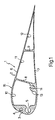
- Number 1 in Fig.1 indicates an aileron consisting of a constant-section tubular element 2 (Fig. 2) formed by forward extrusion and comprising a longitudinal front outer rib 3 having a longitudinal outer groove 4 and a longitudinal inner groove 5 for housing balance weights (not shown).
- Tubular element 2 also comprises integral top and bottom faces 6 and 7 at the opposite transverse ends of rib 3.
- tubular element 2 comprises a longitudinal front inner core 8 and a longitudnal rear inner core 9 dividing the space inside tubular element 2 into three longitudinal ducts 10, 11 and 12.
- a longitudinal rib 13 integral with the bottom end of core 8 and having a longitudinal groove 14 defining a seat for a hinge (not shown) connecting aileron 1 to the respective wing (not shown).
- tubular element 2 presents a finish ed outer surface 15 requiring no further surface processing. Precisely on account of it being extruded, however, tubular element 2 necessarily presents relatively thick walls, for preventing breakage during extrusion, and the weight of which would be unacceptable.
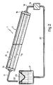
- tubular element 2 is removed by internal chemical milling.
- the opposite ends of ducts 10, 11 and 12 are closed off by covers 16, through which ducts 10, 11 and 12 communicate with a pipe 17 at one end and a pipe 18 at the other.
- Tubular element 2 is tilted slightly upwards, and pipe 18 at the bottom is connected to the delivery end of a pump 19, the inlet end of which is connected by pipe 20 to a tank 21 containing a corrosive solution.
- Pipe 17 terminates in a downturned spout 22 over a degassing funnel 23 fitted to the top of and communicating with tank 21.
- forward-extruded tubular element 2 is fitted on to a support (not shown) in the tilted position shown in Fig.2, and connected to pump 19 and tank 21 by means of pipes 18 and 20.
- pump 19 When pump 19 is started up, corrosive solution is sucked out of tank 21 and supplied by pump 19 to longitudinal ducts 10, 11 and 12.
- the amount of material removed generally depends on how long the corrosive solution is left in contact with the metal, the said solution is pumped along ducts 10, 11 and 12 for the length of time required to obtain the required thickness of tubular element 2.
- aileron 1 is finished and ready for use.
- internal chemical milling in no way affects the excellent surface finish of extruded tubular element 2, thus enabling the materials and labour normally required for surface finishing known control surfaces to be dispensed with.
Landscapes
- Engineering & Computer Science (AREA)
- Chemical & Material Sciences (AREA)
- Mechanical Engineering (AREA)
- Aviation & Aerospace Engineering (AREA)
- Chemical Kinetics & Catalysis (AREA)
- General Chemical & Material Sciences (AREA)
- Materials Engineering (AREA)
- Metallurgy (AREA)
- Organic Chemistry (AREA)
- ing And Chemical Polishing (AREA)
Abstract
A method for manufacturing aircraft control surfaces via forward extrusion of a tubular element (2) having a constant section and longitudinal cores (8,9); which element presents a finished outer surface and a given thickness which is reduced to a predetermined value via internal chemical milling.
Description
- The present invention relates to a method for manufacturing aircraft control surfaces.
- The control surfaces of aircraft in general, and airplanes of any size in particular, usually consist of tubular elements composed of a front longitudinal member, a number of structural ribs, and a top and bottom face riveted together at the trailing edge, as well as to the front longitudinal member and structural ribs.
- Despite enabling the use of structural elements designed and of such a thickness as to minimise weight, the above method nevertheless involves considerable construction cost.
- The aim of the present invention is to provide a method for manufacturing aircraft control surfaces which are both lightweight and relatively cheap to produce.
- With this aim in view, according to the present invention, there is provided a method for manufacturing aircraft control surfaces, characterised by the fact that it comprises stages consisting in:
- forming, by forward extrusion, a tubular element having a constant section and preferably at least one longitudinal core; said tubular element having a finished outer surface and a given thickness;
- reducing the said thickness to a predetermined value via internal chemical milling. - A non-limiting embodiment of the present invention will be described by way of example with reference to the accompanying drawings, in which :
- Fig.1 shows a cross section of an aileron formed using the method according to the present invention;
- Fig.2 shows a schematic view of one stage in the formation of the Fig.1 aileron.
- Number 1 in Fig.1 indicates an aileron consisting of a constant-section tubular element 2 (Fig. 2) formed by forward extrusion and comprising a longitudinal front
outer rib 3 having a longitudinal outer groove 4 and a longitudinalinner groove 5 for housing balance weights (not shown).Tubular element 2 also comprises integral top andbottom faces rib 3. Finally,tubular element 2 comprises a longitudinal front inner core 8 and a longitudnal rearinner core 9 dividing the space insidetubular element 2 into threelongitudinal ducts front duct 10, there extends alongitudinal rib 13 integral with the bottom end of core 8 and having alongitudinal groove 14 defining a seat for a hinge (not shown) connecting aileron 1 to the respective wing (not shown). - In its extruded form,
tubular element 2 presents a finish edouter surface 15 requiring no further surface processing. Precisely on account of it being extruded, however,tubular element 2 necessarily presents relatively thick walls, for preventing breakage during extrusion, and the weight of which would be unacceptable. - As shown in Fig.2, the said excess wall thickness of
tubular element 2 is removed by internal chemical milling. For this purpose, the opposite ends ofducts covers 16, through whichducts pipe 17 at one end and apipe 18 at the other.Tubular element 2 is tilted slightly upwards, andpipe 18 at the bottom is connected to the delivery end of apump 19, the inlet end of which is connected bypipe 20 to atank 21 containing a corrosive solution.Pipe 17 terminates in adownturned spout 22 over a degassingfunnel 23 fitted to the top of and communicating withtank 21. - In actual practice, forward-extruded
tubular element 2 is fitted on to a support (not shown) in the tilted position shown in Fig.2, and connected topump 19 andtank 21 by means ofpipes pump 19 is started up, corrosive solution is sucked out oftank 21 and supplied bypump 19 tolongitudinal ducts ducts tubular element 2. - Subsequent to internal chemical milling as described above, aileron 1 is finished and ready for use. In fact, as already stated, internal chemical milling in no way affects the excellent surface finish of extruded
tubular element 2, thus enabling the materials and labour normally required for surface finishing known control surfaces to be dispensed with.
Claims (5)
1) - A method for manufacturing aircraft control surfaces, characterised by the fact that it comprises stages consisting in :
- forming, by forward extrusion, a tubular element having a constant section and preferably at least one longitudinal core; said tubular element having a finished outer surface and a given thickness;
- reducing the said thickness to a predetermined value via internal chemical milling.
- forming, by forward extrusion, a tubular element having a constant section and preferably at least one longitudinal core; said tubular element having a finished outer surface and a given thickness;
- reducing the said thickness to a predetermined value via internal chemical milling.
2) - A method as claimed in Claim 1, characterised by the fact that the said tubular element presents at least one longitudinal inner core dividing the space inside the said tubular element into at least two longitudinal ducts.
3) - A method as claimed in Claim 1 or 2, characterised by the fact that the said internal chemical milling process is performed by feeding a corrosive solution along the said tubular element for a given length of time.
4) - A method as claimed in Claim 3, characterised by the fact that, during the said chemical milling process, the said tubular element is supported in a tilted position; means being provided for continuously feeding the said corrosive solution from a tank to the bottom end of the said tubular element; and the top end of the said tubular element communicating with the said tank.
5) - A method as claimed in Claim 4, characterised by the fact that, prior to being fed back into the said tank, the said corrosive solution from the said tubular element is degassed.
Priority Applications (1)
| Application Number | Priority Date | Filing Date | Title |
|---|---|---|---|
| EP88106517A EP0338114A1 (en) | 1988-04-22 | 1988-04-22 | Method for manufacturing aircraft control surfaces |
Applications Claiming Priority (1)
| Application Number | Priority Date | Filing Date | Title |
|---|---|---|---|
| EP88106517A EP0338114A1 (en) | 1988-04-22 | 1988-04-22 | Method for manufacturing aircraft control surfaces |
Publications (1)
| Publication Number | Publication Date |
|---|---|
| EP0338114A1 true EP0338114A1 (en) | 1989-10-25 |
Family
ID=8198910
Family Applications (1)
| Application Number | Title | Priority Date | Filing Date |
|---|---|---|---|
| EP88106517A Withdrawn EP0338114A1 (en) | 1988-04-22 | 1988-04-22 | Method for manufacturing aircraft control surfaces |
Country Status (1)
| Country | Link |
|---|---|
| EP (1) | EP0338114A1 (en) |
Cited By (4)
| Publication number | Priority date | Publication date | Assignee | Title |
|---|---|---|---|---|
| WO1996000315A1 (en) * | 1994-06-27 | 1996-01-04 | Melanesia International Trust Company Limited | Chemical milling apparatus and method |
| CN107313049A (en) * | 2017-06-02 | 2017-11-03 | 哈尔滨飞机工业集团有限责任公司 | A kind of equipment for controlling bend pipe variable cross-section milling |
| WO2018089583A1 (en) | 2016-11-11 | 2018-05-17 | Aerovironment, Inc. | Extruded wing protection system and device |
| RU2830314C1 (en) * | 2023-08-09 | 2024-11-18 | Аллан Валерьевич Попович | Wing cantilever semi-finished product manufacturing method |
Citations (4)
| Publication number | Priority date | Publication date | Assignee | Title |
|---|---|---|---|---|
| BE545247A (en) * | ||||
| US3751313A (en) * | 1971-08-23 | 1973-08-07 | Us Army | Method of forming rifling in a gun barrel by chemical milling |
| FR2429147A1 (en) * | 1978-06-20 | 1980-01-18 | Franque Xavier | Extruded aerofoil section for helicopter rotor blade - has internal walls defining parts of cylindrical surface to match mounting tube |
| FR2542645A1 (en) * | 1983-03-15 | 1984-09-21 | Cabrol Lucien | Method for producing a support structure for an aircraft, and the structure obtained |
-
1988
- 1988-04-22 EP EP88106517A patent/EP0338114A1/en not_active Withdrawn
Patent Citations (4)
| Publication number | Priority date | Publication date | Assignee | Title |
|---|---|---|---|---|
| BE545247A (en) * | ||||
| US3751313A (en) * | 1971-08-23 | 1973-08-07 | Us Army | Method of forming rifling in a gun barrel by chemical milling |
| FR2429147A1 (en) * | 1978-06-20 | 1980-01-18 | Franque Xavier | Extruded aerofoil section for helicopter rotor blade - has internal walls defining parts of cylindrical surface to match mounting tube |
| FR2542645A1 (en) * | 1983-03-15 | 1984-09-21 | Cabrol Lucien | Method for producing a support structure for an aircraft, and the structure obtained |
Non-Patent Citations (1)
| Title |
|---|
| METAL FINISHING ABSTRACTS, vol. 26, no. 6, November-December 1984, pages 374-375, Teddington, Middlesex, GB; & SU-A-1 980 863 (VITEBSK LIGHT IND. TECHNOL. INST., VITBEBSK, USSR) 22-07-1980 * |
Cited By (16)
| Publication number | Priority date | Publication date | Assignee | Title |
|---|---|---|---|---|
| WO1996000315A1 (en) * | 1994-06-27 | 1996-01-04 | Melanesia International Trust Company Limited | Chemical milling apparatus and method |
| US5961771A (en) * | 1994-06-27 | 1999-10-05 | Melanesia International Trust Company Limited | Chemical milling apparatus |
| US6203716B1 (en) | 1994-06-27 | 2001-03-20 | Melanesia International Trust Company Limited | Method of chemical milling |
| US11535361B2 (en) | 2016-11-11 | 2022-12-27 | Aerovironment, Inc. | Extruded wing protection system and device |
| WO2018089583A1 (en) | 2016-11-11 | 2018-05-17 | Aerovironment, Inc. | Extruded wing protection system and device |
| CN110225861A (en) * | 2016-11-11 | 2019-09-10 | 威罗门飞行公司 | The alar part protection system and device of extruding |
| EP3538436A4 (en) * | 2016-11-11 | 2020-06-17 | AeroVironment, Inc. | EXTRUDED WING PROTECTION SYSTEM AND DEVICE |
| US10710703B2 (en) | 2016-11-11 | 2020-07-14 | Aerovironment, Inc. | Extruded control surface having a knuckle and notches |
| AU2017356989B2 (en) * | 2016-11-11 | 2023-02-16 | Aerovironment, Inc. | Extruded wing protection system and device |
| CN110225861B (en) * | 2016-11-11 | 2023-08-08 | 威罗门飞行公司 | Extruded wing protection system and apparatus |
| US20230286642A1 (en) * | 2016-11-11 | 2023-09-14 | Aerovironment, Inc. | Extruded wing protection system and device |
| US12377958B2 (en) | 2016-11-11 | 2025-08-05 | Aerovironment, Inc. | Extruded wing protection system and device |
| CN107313049A (en) * | 2017-06-02 | 2017-11-03 | 哈尔滨飞机工业集团有限责任公司 | A kind of equipment for controlling bend pipe variable cross-section milling |
| RU2830314C1 (en) * | 2023-08-09 | 2024-11-18 | Аллан Валерьевич Попович | Wing cantilever semi-finished product manufacturing method |
| RU231420U1 (en) * | 2024-06-06 | 2025-01-28 | Аллан Валерьевич Попович | Semi-finished product for manufacturing wing console |
| RU2840547C1 (en) * | 2024-09-21 | 2025-05-26 | Попович Аллан Валерьевич | Method of making semi-finished product of outer wing with flexible web |
Similar Documents
| Publication | Publication Date | Title |
|---|---|---|
| US2804767A (en) | Gun type trowel | |
| US4726548A (en) | Airfoil self energizing boundary layer control system | |
| CN107000827B (en) | Control surface element for an aircraft | |
| US5111767A (en) | Boat hulls | |
| EP3450321B1 (en) | Conformable tank fabricated using additive manufacturing | |
| GB2109760A (en) | Fuel tank | |
| US10214277B1 (en) | System and method for improving fuel storage within a wing of an aircraft | |
| WO2015171841A1 (en) | Three-dimensional printing excess deposited particulate handling | |
| EP0133497A2 (en) | Regenerative pump for transferring a fuel | |
| KR20190077394A (en) | Extruded wing protection systems and devices | |
| US4321816A (en) | Metal tube and apparatus and method for manufacturing the same | |
| US5156564A (en) | Toy bubble-forming missile-like device | |
| JP2010042799A (en) | Aircraft wing | |
| EP0388068A2 (en) | Jettisonable aerodynamic control surfaces | |
| US2623599A (en) | Propeller blade stress distributing means | |
| DE2928579C2 (en) | Sailboard hull | |
| DE8717657U1 (en) | Cast body model | |
| EP1963119B1 (en) | Fuel tank and fuel extraction system for an auxiliary heating unit | |
| CN117550115A (en) | A kind of wing and unmanned aerial vehicle | |
| US9682401B2 (en) | Coating application | |
| US2690151A (en) | Means and method of making airfoils | |
| EP1149015B1 (en) | Jet propulsion pump | |
| EP0507612B1 (en) | Road tanker | |
| DE60101764T2 (en) | Vehicle air conditioning | |
| US3078911A (en) | Apparatus for the assembly of an airfoil |
Legal Events
| Date | Code | Title | Description |
|---|---|---|---|
| PUAI | Public reference made under article 153(3) epc to a published international application that has entered the european phase |
Free format text: ORIGINAL CODE: 0009012 |
|
| AK | Designated contracting states |
Kind code of ref document: A1 Designated state(s): AT BE CH DE ES FR GB GR LI LU NL SE |
|
| STAA | Information on the status of an ep patent application or granted ep patent |
Free format text: STATUS: THE APPLICATION IS DEEMED TO BE WITHDRAWN |
|
| 18D | Application deemed to be withdrawn |
Effective date: 19900426 |