EP0338019B1 - Multiple cyclone separator - Google Patents
Multiple cyclone separator Download PDFInfo
- Publication number
- EP0338019B1 EP0338019B1 EP88900706A EP88900706A EP0338019B1 EP 0338019 B1 EP0338019 B1 EP 0338019B1 EP 88900706 A EP88900706 A EP 88900706A EP 88900706 A EP88900706 A EP 88900706A EP 0338019 B1 EP0338019 B1 EP 0338019B1
- Authority
- EP
- European Patent Office
- Prior art keywords
- unit
- chamber
- dust
- flow
- outlet
- Prior art date
- Legal status (The legal status is an assumption and is not a legal conclusion. Google has not performed a legal analysis and makes no representation as to the accuracy of the status listed.)
- Expired - Lifetime
Links
- 239000000428 dust Substances 0.000 claims abstract description 54
- 239000007789 gas Substances 0.000 claims abstract description 42
- 238000000746 purification Methods 0.000 claims abstract description 32
- 239000002245 particle Substances 0.000 claims abstract description 17
- 239000007787 solid Substances 0.000 claims abstract description 6
- 238000000926 separation method Methods 0.000 claims abstract description 3
- 239000012535 impurity Substances 0.000 claims description 6
- 239000003546 flue gas Substances 0.000 claims description 2
- 238000009825 accumulation Methods 0.000 description 1
- 230000006978 adaptation Effects 0.000 description 1
- 239000003795 chemical substances by application Substances 0.000 description 1
- 230000007812 deficiency Effects 0.000 description 1
- 230000001419 dependent effect Effects 0.000 description 1
- 230000005484 gravity Effects 0.000 description 1
- 230000001771 impaired effect Effects 0.000 description 1
- 238000005192 partition Methods 0.000 description 1
- 238000011084 recovery Methods 0.000 description 1
Images

Classifications
-
- B—PERFORMING OPERATIONS; TRANSPORTING
- B01—PHYSICAL OR CHEMICAL PROCESSES OR APPARATUS IN GENERAL
- B01D—SEPARATION
- B01D45/00—Separating dispersed particles from gases or vapours by gravity, inertia, or centrifugal forces
- B01D45/12—Separating dispersed particles from gases or vapours by gravity, inertia, or centrifugal forces by centrifugal forces
-
- B—PERFORMING OPERATIONS; TRANSPORTING
- B04—CENTRIFUGAL APPARATUS OR MACHINES FOR CARRYING-OUT PHYSICAL OR CHEMICAL PROCESSES
- B04C—APPARATUS USING FREE VORTEX FLOW, e.g. CYCLONES
- B04C3/00—Apparatus in which the axial direction of the vortex flow following a screw-thread type line remains unchanged ; Devices in which one of the two discharge ducts returns centrally through the vortex chamber, a reverse-flow vortex being prevented by bulkheads in the central discharge duct
- B04C3/04—Multiple arrangement thereof
-
- B—PERFORMING OPERATIONS; TRANSPORTING
- B04—CENTRIFUGAL APPARATUS OR MACHINES FOR CARRYING-OUT PHYSICAL OR CHEMICAL PROCESSES
- B04C—APPARATUS USING FREE VORTEX FLOW, e.g. CYCLONES
- B04C3/00—Apparatus in which the axial direction of the vortex flow following a screw-thread type line remains unchanged ; Devices in which one of the two discharge ducts returns centrally through the vortex chamber, a reverse-flow vortex being prevented by bulkheads in the central discharge duct
- B04C3/06—Construction of inlets or outlets to the vortex chamber
Definitions
- This invention relates to a purification unit for separating solid particles from gases according to the preamble of claim 1 (US-A-2 806 551).
- Dust separatos comprising one single flow cylinder with associated rotation generator connected to the inlet end of the cylinder and having an outlet diffusor projecting concentrically into the outlet end of the flow cylinder are previously known.
- This type of dust separator has appeared to operate very satisfactorily as far as flue gases and other gases containing particles of a small mass are concerned and purifies such gases up to about 99.7% which is quite acceptable in most connections that may be concerned with the present type of dust separator.
- a disadvantage of this known dust separator is a very low capacity, i.e. below 600 m3 gas per hour, and therefore it has not been used to any large extent despite its high efficiency in purification.
- the purification unit has been given the characteristic features defined in claim 1.
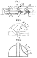
- Fig. 1 shows a section of a purification unit according to the invention
- Figs. 2 and 3 are perspective views on a smaller scale of a module or group of nine and three, respectively, dust separating units connected in parallel
- Fig. 4 shows a modified design with a rotary head mounted before each dust separating unit
- Fig. 5 is a partial end view of a rotary head
- Fig. 6 shows a section taken substantially along the line VI-VI in Fig. 5.
- the purification unit of the invention for separation of dust and other solid particles from impurified gases inclusive of air comprises a number of similar dust separating units 1 of cyclone type which are arranged in rows in a casing 2 having an inlet 3 for the gas or gases to be purified and an outlet 4 for the gas or gases purified.
- Each dust separator 1 included in the unit comprises a fixed rotary head 6 located in an inlet chamber 5 for setting incoming gas in rotation, preferably a helical rotary motion, and a flow cylinder 7 connected to the rotary head 6 and arranged in a closed dust collecting chamber 8 common to all the flow cylinders 7 of the dust separators included in the unit.
- This chamber is quite separated from the inlet chamber 5 which is common to all units 1, and a collecting container not shown on the drawings can be connected to the dust collecting chamber 8.
- Gas intended for purification arrives at the chamber 5 via the inlet 3 and a helical rotary motion is imparted to the gas by the rotary heads 6 through the following flow cylinders 7, dust and other solid particles accompanying incoming gas being concentrated thanks to their inertia, i.e. through the action of centrifugal force, along the inside of the respective flow cylinder 7.
- the rotary head 6 of each dust separating unit has a dome- or cup-shaped mantle of an inside diameter larger than the following cylinder 7 and is provided in its mantle with a number of, for example five, uniformly distributed, inlet openings 9 located substantially in a radial plane and hollows or recesses 10 in the mantle surface leading to the respective opening 9, the width and depth of said recesses increasing towards the respective opening and which have a concave curved form in cross-section, as is best apparent from Figs. 3 and 6, each portion 11 of the mantle defining a hollow or recess 10 functioning as guide blades for setting incoming gas in rotary motion.
- Each inlet opening 9 in a rotary head 6 has its upper limiting line 9a so located that it borders on or preferably overlaps the lower limiting line 9b of the opening.
- each flow cylinder there is arranged an outlet diffusor 12 ending in an outlet chamber 13 for the purified gas streaming out of the units 1, said outlet chamber being quite separated from the dust collecting chamber 8.
- Each outlet diffusor 12 extends concentrically into its flow cylinder 7 with a funnel-shaped inlet portion 14 and forms together with the end section of the flow cylinder an annular gap 15 ending in the closed dust collecting chamber 8.
- Impurified gas entering through the inlet 3 of the unit is distributed on the different dust separating units 1 and is set in rotation by the rotary head 6 of the respective unit and the helically rotating gas stream in each flow cylinder 7 continues through the cylinder 7 and the particles included in the gas are thrown by the influence of the centrifugal force against the cylinder wall and form a rotating dust film.
- the portion thereof streaming out of the diffusor is purified while the remaining portion of the gas stream, i.e. the portion containing the dust film and rotating close to the cylinder wall continues in a rotating way into and out through the diffusor gap 15 to the collecting chamber 8 where the particles fall down by the influence of gravity and are preferably collected in a container.
- the number of dust separators 1 included in a unit according to the invention is adapted with respect to the amount of gas to be purified per unit of time.
- the separating portion or portions of the unit can be composed of cassettes or modules 16 each comprising a suitable number, for example 1, 2-8 or 9, of dust separating units 1 enclosed in a casing 17 with at least one open side and easy to join and connect to a collecting container of a suitable size. Examples of two such modules 16 are shown in Figs. 2 and 3 containing nine and three, respectively, units 1.
- a steplessly adjustable blower 18 is connected to the dust collecting chamber 8 of the unit and is associated with the chamber 8 through one or several suction lines 19 depending on i.a. the number of dust separating units 1 belonging to the chamber 8 for maintaining a negative pressure within said chamber 8.
- Each suction line 19 should be connected to the dust collecting chamber 8 spaced from the diffusor gaps 15 and preferably as much remote from these as possible.
- One or several of the suction lines 19 can also extend into the chamber 8 between the units 1 and have their inlet opening located at some distance from the walls of the casing.
- the blower 18 is connected with its pressure line 20 to the channel leading to the unit before the inlet 3 of the unit or to another space, for example the atmosphere or the chamber, the air of which is purified, which is possible thanks to the fact that the return flow caused by the blower 18 is such a small portion of the total main flow through the unit which is less than 0.1% and maximally 3% and is almost purified.
- an operating or steering means 21 for the stepless adjustment of the blower 18 there is arranged an operating or steering means 21, by means of which, thus, the negative pressure in the dust collecting chamber 8 can be changed steplessly within wide limits.
- An equalization of the differential pressure between the flow cylinders ending in the dust collecting chamber 8 in the area around the gap 15 is achieved, the result of said equalization being that the flow cylinders 7 do not disturb each other but operate as separate units, i.e. as if they were alone and quite separated from each other.
- several dust separating units connected in parallel which contain purification means capable of purifying impurified gases at least as effectively as a plant containing one single dust separator 1 of the relative type and thus to at least 99.7%.
- the purification unit of this invention also enables an optimal purification of impurified gases independently of the size and mass of the particles forming the impurities.
- the purification unit of the invention can for instance be used for recovery of blast agents from air blast which has not been possible by means of known purification units of this type, and this is due to the possibility of achieving a high current rate through the diffusor gaps 15, and in this way each tendency to a braking accumulation of particles in front of the diffusor gaps within the flow cylinders 7 is eliminated.
- the flow through this purification unit is decided by a main blower 26 which can be arranged either before the inlet 3 of the unit or after its outlet 4. This latter location of the main blower is shown in Fig. 1.
- a detecting means connected to the operating or control means of the blower can be arranged in the outlet 4, said means detecting the amount of impurities in the gas streaming out through the outlet and, in case this amount will increase over a predetermined value, actuates the control means of the blower to adjust the blower until said predetermined value is reached again.
Abstract
Description
- This invention relates to a purification unit for separating solid particles from gases according to the preamble of claim 1 (US-A-2 806 551).
- Dust separatos comprising one single flow cylinder with associated rotation generator connected to the inlet end of the cylinder and having an outlet diffusor projecting concentrically into the outlet end of the flow cylinder are previously known. This type of dust separator has appeared to operate very satisfactorily as far as flue gases and other gases containing particles of a small mass are concerned and purifies such gases up to about 99.7% which is quite acceptable in most connections that may be concerned with the present type of dust separator. However, a disadvantage of this known dust separator is a very low capacity, i.e. below 600 m³ gas per hour, and therefore it has not been used to any large extent despite its high efficiency in purification.
- In order to improve the capacity several such dust separators have been connected in parallel by arranging the flow pipes of all dust separators in a common closed dust collecting chamber in which the gap of the dust separators between flow cylinder and outlet diffusor ends for discharge of separate particles in the collecting chamger. An example of such a dust separating unit is shown in SE-A-304 668. Thus, parallel connection of a plurality of dust separators to one unit has been tested in practice but no better purification degree than about 86%, i.e. a purification degree that is too low to be considered acceptable in most connections, has been obtained.
- In order to overcome the deficiencies in prior art purification units and to provide a purification unit having a higher degree of automatic control in dependence on the amount of impurities in gas streaming out through the outlet thereof, the purification unit has been given the characteristic features defined in
claim 1. - Other advantageous features are given in the dependent claims.
- The invention is described in the following in greater detail with reference to the enclosed drawings, wherein Fig. 1 shows a section of a purification unit according to the invention, Figs. 2 and 3 are perspective views on a smaller scale of a module or group of nine and three, respectively, dust separating units connected in parallel, Fig. 4 shows a modified design with a rotary head mounted before each dust separating unit, Fig. 5 is a partial end view of a rotary head and Fig. 6 shows a section taken substantially along the line VI-VI in Fig. 5.
- The purification unit of the invention for separation of dust and other solid particles from impurified gases inclusive of air comprises a number of similar dust separating
units 1 of cyclone type which are arranged in rows in a casing 2 having aninlet 3 for the gas or gases to be purified and anoutlet 4 for the gas or gases purified. Eachdust separator 1 included in the unit comprises a fixedrotary head 6 located in aninlet chamber 5 for setting incoming gas in rotation, preferably a helical rotary motion, and aflow cylinder 7 connected to therotary head 6 and arranged in a closeddust collecting chamber 8 common to all theflow cylinders 7 of the dust separators included in the unit. This chamber is quite separated from theinlet chamber 5 which is common to allunits 1, and a collecting container not shown on the drawings can be connected to thedust collecting chamber 8. Gas intended for purification arrives at thechamber 5 via theinlet 3 and a helical rotary motion is imparted to the gas by therotary heads 6 through the followingflow cylinders 7, dust and other solid particles accompanying incoming gas being concentrated thanks to their inertia, i.e. through the action of centrifugal force, along the inside of therespective flow cylinder 7. - The
rotary head 6 of each dust separating unit has a dome- or cup-shaped mantle of an inside diameter larger than the followingcylinder 7 and is provided in its mantle with a number of, for example five, uniformly distributed,inlet openings 9 located substantially in a radial plane and hollows orrecesses 10 in the mantle surface leading to therespective opening 9, the width and depth of said recesses increasing towards the respective opening and which have a concave curved form in cross-section, as is best apparent from Figs. 3 and 6, eachportion 11 of the mantle defining a hollow or recess 10 functioning as guide blades for setting incoming gas in rotary motion. Each inlet opening 9 in arotary head 6 has its upperlimiting line 9a so located that it borders on or preferably overlaps the lowerlimiting line 9b of the opening. - At the outlet end of each flow cylinder there is arranged an
outlet diffusor 12 ending in anoutlet chamber 13 for the purified gas streaming out of theunits 1, said outlet chamber being quite separated from thedust collecting chamber 8. Eachoutlet diffusor 12 extends concentrically into itsflow cylinder 7 with a funnel-shaped inlet portion 14 and forms together with the end section of the flow cylinder anannular gap 15 ending in the closeddust collecting chamber 8. - Impurified gas entering through the
inlet 3 of the unit is distributed on the different dust separatingunits 1 and is set in rotation by therotary head 6 of the respective unit and the helically rotating gas stream in eachflow cylinder 7 continues through thecylinder 7 and the particles included in the gas are thrown by the influence of the centrifugal force against the cylinder wall and form a rotating dust film. When the gas stream reaches theoutlet diffusor 12 the portion thereof streaming out of the diffusor is purified while the remaining portion of the gas stream, i.e. the portion containing the dust film and rotating close to the cylinder wall continues in a rotating way into and out through thediffusor gap 15 to thecollecting chamber 8 where the particles fall down by the influence of gravity and are preferably collected in a container. - The number of
dust separators 1 included in a unit according to the invention is adapted with respect to the amount of gas to be purified per unit of time. In order to make this adaptation easier the separating portion or portions of the unit can be composed of cassettes ormodules 16 each comprising a suitable number, for example 1, 2-8 or 9, of dust separatingunits 1 enclosed in acasing 17 with at least one open side and easy to join and connect to a collecting container of a suitable size. Examples of twosuch modules 16 are shown in Figs. 2 and 3 containing nine and three, respectively,units 1. - A steplessly
adjustable blower 18 is connected to thedust collecting chamber 8 of the unit and is associated with thechamber 8 through one orseveral suction lines 19 depending on i.a. the number of dust separatingunits 1 belonging to thechamber 8 for maintaining a negative pressure within saidchamber 8. Eachsuction line 19 should be connected to thedust collecting chamber 8 spaced from thediffusor gaps 15 and preferably as much remote from these as possible. One or several of thesuction lines 19 can also extend into thechamber 8 between theunits 1 and have their inlet opening located at some distance from the walls of the casing. Theblower 18 is connected with itspressure line 20 to the channel leading to the unit before theinlet 3 of the unit or to another space, for example the atmosphere or the chamber, the air of which is purified, which is possible thanks to the fact that the return flow caused by theblower 18 is such a small portion of the total main flow through the unit which is less than 0.1% and maximally 3% and is almost purified. - For the stepless adjustment of the
blower 18 there is arranged an operating orsteering means 21, by means of which, thus, the negative pressure in thedust collecting chamber 8 can be changed steplessly within wide limits. An equalization of the differential pressure between the flow cylinders ending in thedust collecting chamber 8 in the area around thegap 15 is achieved, the result of said equalization being that theflow cylinders 7 do not disturb each other but operate as separate units, i.e. as if they were alone and quite separated from each other. In this way several dust separating units connected in parallel are obtained which contain purification means capable of purifying impurified gases at least as effectively as a plant containing onesingle dust separator 1 of the relative type and thus to at least 99.7%. Thanks to this possibility of adjusting the negative pressure in thedust collecting chamber 8 steplessly it is also possible to control, i.e. increase or reduce, the flow rate through thediffusor gaps 15, and in this way the purification unit of this invention also enables an optimal purification of impurified gases independently of the size and mass of the particles forming the impurities. The purification unit of the invention can for instance be used for recovery of blast agents from air blast which has not been possible by means of known purification units of this type, and this is due to the possibility of achieving a high current rate through thediffusor gaps 15, and in this way each tendency to a braking accumulation of particles in front of the diffusor gaps within theflow cylinders 7 is eliminated. As a result of this particles may be sucked along with the purified gas through thediffusors 12, the consequence being an impaired purification. A high flow rate through thediffusor gaps 15 gives a higher rotation speed for the gas within theflow cylinders 7 and consequently also a more efficient concentration of heavy particles. - In order to further increase the rotary speed within the
flow cylinders 7 there is arranged anotherrotary head 22 of the same type as therotary head 6 of the dust separating units in front of eachdust separating unit 1 and coaxially with itsrotary head 6. These are attached in awall 23 between theinlet 3 of the unit and thewall 24 supporting the dust separatingunits 1. A first purification of the gas takes place in the space between these two walls in that the heaviest particles are separated from the gas thanks to the rotary motion in which the impurified gas is set by the furtherrotary head 22, and the rotary speed of this gas is thereafter increased by therotary head 6 of the respective dust separating unit resulting in a very efficient purification in the second step, i.e. in theflow cylinders 7, and thediffusor gaps 15 thereof ending in thechamber 8 which is defined by thewalls 24 and 25, the latter of which is the partition between thechamber 8 and theoutlet chamber 13. - The flow through this purification unit is decided by a
main blower 26 which can be arranged either before theinlet 3 of the unit or after itsoutlet 4. This latter location of the main blower is shown in Fig. 1. - This invention is not restricted to what has been described above and shown on the drawings but it can be changed and modified in several different manners within the scope of the inventive idea defined in the appended claims. Thus, the alternative with one dust separating
unit 1 and a rotary head mounted before this arranged as a purification unit with blower to obtain a negative pressure in the dust collecting chamber is included in the inventive idea. - For automatic control of the purification unit in dependence on the amount of impurities in gas streaming out through the outlet 4 a detecting means connected to the operating or control means of the blower can be arranged in the
outlet 4, said means detecting the amount of impurities in the gas streaming out through the outlet and, in case this amount will increase over a predetermined value, actuates the control means of the blower to adjust the blower until said predetermined value is reached again.
Claims (9)
- A purification unit for separation of solid particles from gases, for example flue gases, air mixed with dust and air blast, said unit comprising one or more groups of each a number of mutually parallel flow cylinders (7) arranged in a common chamber (8), said cylinders (7) being each connected at their inlet ends to a fixed rotary head (6) for setting incoming gas in rotary motion in the respective flow cylinder (7) and having each an outlet end into which an outlet diffusor (12) projects concentrically, through which purified gas streams out of the unit, said outlet diffusor having an inlet portion surrounded by the flow cylinder and said inlet portion of the outlet diffusor (12) forming together with the surrounding cylinder an annular gap (15) through which the separated solid particles stream out to said chamber (8) serving as a dust collection chamber, dust collection chamber (8) being connected to a blower means through at least one suction line (19) in order to maintain a negative pressure in said dust collection chamber for equalizing arising pressure differences between the flow cylinders (7) in the area of the respective gap (15) thereof, characterized in that a steplessly adjustable blower is used and in that the outlet (4) of the unit is provided with means for detecting the amount of impurities in the outflow gas, said detecting means being connected to operating or control means of the blower means (18) to control the unit by adjusting the negative pressure in dependence on the amount of impurities in the outflow gas through said outlet (4).
- The purification unit of claim 1, characterized in that the pressure side of the blower is connected to the inlet line of the unit before the inlet (3) of the unit or to another space, for example the atmosphere.
- The purification unit of claim 1 or 2, characterized in that the suction line of the blower is associated with the dust collecting chamber (8) spaced, preferably maximally spaced, from the gap (15) of the flow cylinders ending in said chamber.
- The purification unit of any one of the preceding claims, characterized in that the blower (18) is connected to the dust collecting chamber (8) by way of several suction lines (19).
- The purification unit of claim 4, characterized in that one or more suction lines extend into the dust collecting chamber (8).
- The purification unit of any one of the preceding claims, characterized in that another rotary head (22) for setting incoming gas in rotary motion before its entry into the dust separating units (1) is arranged between the inlet (3) of the unit and the rotary heads (6) of the dust separating units coaxially with each of these heads (6).
- The purification unit of claim 6, characterized in that the further rotary heads (22) end in a common chamber which is the collecting chamber of the particles separated due to the rotation in which incoming gas is set by the further rotary heads (22).
- The purification unit of any one of the preceding claims, characterized in that the flow produced by the steplessly adjustable blower (18) is such a small portion of the main flow through the unit that it is less than 0.1% and not greater than 3% and preferably not greater than 2%.
- The purification unit of claim 7 and 8, characterized by the alternative that the unit comprises one single dust separating unit (1) provided with said further rotary head (22).
Priority Applications (1)
| Application Number | Priority Date | Filing Date | Title |
|---|---|---|---|
| AT88900706T ATE89185T1 (en) | 1986-12-29 | 1987-12-22 | MULTIPLE CYCLONE SEPARATOR. |
Applications Claiming Priority (2)
| Application Number | Priority Date | Filing Date | Title |
|---|---|---|---|
| SE8605590 | 1986-12-22 | ||
| SE8605590A SE467092B (en) | 1986-12-29 | 1986-12-29 | GASRENINGSAGGREGAT |
Publications (2)
| Publication Number | Publication Date |
|---|---|
| EP0338019A1 EP0338019A1 (en) | 1989-10-25 |
| EP0338019B1 true EP0338019B1 (en) | 1993-05-12 |
Family
ID=20366777
Family Applications (1)
| Application Number | Title | Priority Date | Filing Date |
|---|---|---|---|
| EP88900706A Expired - Lifetime EP0338019B1 (en) | 1986-12-29 | 1987-12-22 | Multiple cyclone separator |
Country Status (11)
| Country | Link |
|---|---|
| US (1) | US5009684A (en) |
| EP (1) | EP0338019B1 (en) |
| JP (1) | JPH02501901A (en) |
| AT (1) | ATE89185T1 (en) |
| AU (1) | AU612618B2 (en) |
| BR (1) | BR8707932A (en) |
| DE (1) | DE3785854T2 (en) |
| FI (1) | FI88877C (en) |
| RU (1) | RU2014902C1 (en) |
| SE (1) | SE467092B (en) |
| WO (1) | WO1988004953A1 (en) |
Cited By (1)
| Publication number | Priority date | Publication date | Assignee | Title |
|---|---|---|---|---|
| RU2504439C1 (en) * | 2012-07-17 | 2014-01-20 | Федеральное государственное бюджетное образовательное учреждение высшего профессионального образования "Национальный минерально-сырьевой университет "Горный" | Hydraulic cyclone automatic control |
Families Citing this family (4)
| Publication number | Priority date | Publication date | Assignee | Title |
|---|---|---|---|---|
| IT1245899B (en) * | 1991-04-29 | 1994-10-25 | Gd Spa | CYCLONE EXHAUST FOR WASTE MATERIALS WITH LOW WEIGHT / SURFACE RATIO |
| US20080168899A1 (en) * | 2007-01-12 | 2008-07-17 | American Farm Implement & Specialty, Inc. | Separation and collection of particulates from an air stream |
| DE102011121630B4 (en) * | 2011-12-20 | 2013-09-26 | Mann + Hummel Gmbh | Filter device and intake system |
| CN111804446B (en) * | 2020-07-15 | 2024-03-22 | 重庆科技学院 | Shale gas detector dust removal precipitation device |
Family Cites Families (22)
| Publication number | Priority date | Publication date | Assignee | Title |
|---|---|---|---|---|
| US2119478A (en) * | 1937-02-12 | 1938-05-31 | Prat Daniel Corp | Dust catcher |
| US2209339A (en) * | 1937-07-06 | 1940-07-30 | Int Precipitation Co | Variable flow dust collector |
| GB701593A (en) * | 1951-02-28 | 1953-12-30 | Howden James & Co Ltd | Improvements in or relating to centrifugal dust collectors |
| US2806551A (en) * | 1951-10-16 | 1957-09-17 | Oswald X Heinrich | Centrifugal dust collector with laminar gas flow |
| US2731102A (en) * | 1952-05-09 | 1956-01-17 | Fram Corp | Apparatus for removing heavy dust from air |
| US2696895A (en) * | 1952-08-25 | 1954-12-14 | Research Corp | Apparatus for separating suspended materials from gas |
| US2776725A (en) * | 1954-05-20 | 1957-01-08 | Phillips Petroleum Co | Carbon black collecting and conveying systems |
| US2963109A (en) * | 1957-02-11 | 1960-12-06 | Roger S Brookman | Centrifugal type separating apparatus |
| US3236031A (en) * | 1963-04-25 | 1966-02-22 | American Air Filter Co | Wet dust separator |
| SE304668B (en) * | 1963-12-17 | 1968-09-30 | T Bieth | |
| NL276188A (en) * | 1966-09-19 | |||
| US3469566A (en) * | 1967-01-19 | 1969-09-30 | Hastings Mfg Co | Centrifugal air precleaner with blower |
| US3520114A (en) * | 1968-06-28 | 1970-07-14 | Pall Corp | Vortex air cleaner assembly having uniform particle removal efficiency throughout the array of air cleaners |
| US3668825A (en) * | 1969-08-28 | 1972-06-13 | Nat Dust Collector Corp | Method and apparatus for determining the difficulty of removing pollutants by wet scrubbing action |
| US3707830A (en) * | 1971-05-18 | 1973-01-02 | Bahco Ventilation Ab | Cyclone separator |
| US3915679A (en) * | 1973-04-16 | 1975-10-28 | Pall Corp | Vortex air cleaner array |
| US3825212A (en) * | 1973-07-10 | 1974-07-23 | Boeing Co | Aircraft heating and ventilating system |
| US4050913A (en) * | 1974-06-28 | 1977-09-27 | Pall Corporation | Vortex air cleaner assembly with acoustic attenuator |
| US4242115A (en) * | 1979-02-05 | 1980-12-30 | Donaldson Company, Inc. | Air cleaner assembly |
| DE2918765A1 (en) * | 1979-05-10 | 1980-11-13 | Kloeckner Humboldt Deutz Ag | Centrifugal dust separator system with several stages |
| US4473326A (en) * | 1980-03-19 | 1984-09-25 | Gebruder Buhler A.G. | Method of controlling delivery conditions in a pneumatic conveyor line, and mill pneumatics for implementing this method |
| US4407663A (en) * | 1982-06-30 | 1983-10-04 | Dollinger Corporation | Modular spin filters and housing therefor |
-
1986
- 1986-12-29 SE SE8605590A patent/SE467092B/en unknown
-
1987
- 1987-12-22 US US07/378,184 patent/US5009684A/en not_active Expired - Fee Related
- 1987-12-22 BR BR8707932A patent/BR8707932A/en not_active IP Right Cessation
- 1987-12-22 AU AU11077/88A patent/AU612618B2/en not_active Ceased
- 1987-12-22 WO PCT/SE1987/000627 patent/WO1988004953A1/en active IP Right Grant
- 1987-12-22 EP EP88900706A patent/EP0338019B1/en not_active Expired - Lifetime
- 1987-12-22 AT AT88900706T patent/ATE89185T1/en active
- 1987-12-22 DE DE8888900706T patent/DE3785854T2/en not_active Expired - Fee Related
- 1987-12-22 JP JP63500932A patent/JPH02501901A/en active Pending
-
1989
- 1989-06-22 FI FI893072A patent/FI88877C/en not_active IP Right Cessation
- 1989-06-29 RU SU894614381A patent/RU2014902C1/en active
Cited By (1)
| Publication number | Priority date | Publication date | Assignee | Title |
|---|---|---|---|---|
| RU2504439C1 (en) * | 2012-07-17 | 2014-01-20 | Федеральное государственное бюджетное образовательное учреждение высшего профессионального образования "Национальный минерально-сырьевой университет "Горный" | Hydraulic cyclone automatic control |
Also Published As
| Publication number | Publication date |
|---|---|
| FI88877B (en) | 1993-04-15 |
| DE3785854T2 (en) | 1993-09-23 |
| RU2014902C1 (en) | 1994-06-30 |
| WO1988004953A1 (en) | 1988-07-14 |
| SE8605590L (en) | 1988-06-30 |
| FI88877C (en) | 1993-07-26 |
| SE467092B (en) | 1992-05-25 |
| AU612618B2 (en) | 1991-07-18 |
| DE3785854D1 (en) | 1993-06-17 |
| FI893072A (en) | 1989-06-22 |
| JPH02501901A (en) | 1990-06-28 |
| AU1107788A (en) | 1988-07-27 |
| US5009684A (en) | 1991-04-23 |
| FI893072A0 (en) | 1989-06-22 |
| ATE89185T1 (en) | 1993-05-15 |
| BR8707932A (en) | 1990-02-13 |
| EP0338019A1 (en) | 1989-10-25 |
| SE8605590D0 (en) | 1986-12-29 |
Similar Documents
| Publication | Publication Date | Title |
|---|---|---|
| US4721561A (en) | Centrifugal force separator | |
| CA1285499C (en) | Air purifier | |
| US3710561A (en) | Apparatus for separating solid particles suspended in a gaseous stream | |
| US4655804A (en) | Hopper gas distribution system | |
| US4198290A (en) | Dust separating equipment | |
| EP0063288B1 (en) | A device for a dust filter | |
| US6270544B1 (en) | Cyclone separator having a tubular member with slit-like openings surrounding a central outlet pipe | |
| US4618415A (en) | Tobacco separator | |
| US2209339A (en) | Variable flow dust collector | |
| EP0338019B1 (en) | Multiple cyclone separator | |
| US4227900A (en) | Apparatus for filtering gas streams | |
| US3074219A (en) | Mechanical dust collector | |
| EP0139422B1 (en) | Tobacco separator | |
| US20050011172A1 (en) | Filter unit | |
| RU2033845C1 (en) | Inertial air purifier | |
| CN85104117A (en) | Separator using centrifugal force | |
| SU1184550A2 (en) | Rotary dust separator | |
| SU1542626A1 (en) | Apparatus for separating and monitoring purity of air | |
| RU2000855C1 (en) | Grain-cleaning machine pneumatic system | |
| SU1745371A1 (en) | Pneumatic separator | |
| CN213529650U (en) | Wind speed adjusting mechanism of winnowing machine | |
| CN2268580Y (en) | Vertical vortex low resistance particle separator | |
| CN209791170U (en) | Smoke and dust minimum discharge apparatus | |
| SU1165435A1 (en) | Inertial dust separator | |
| KR840001287Y1 (en) | Separating by centrifugal forces |
Legal Events
| Date | Code | Title | Description |
|---|---|---|---|
| PUAI | Public reference made under article 153(3) epc to a published international application that has entered the european phase |
Free format text: ORIGINAL CODE: 0009012 |
|
| 17P | Request for examination filed |
Effective date: 19890602 |
|
| AK | Designated contracting states |
Kind code of ref document: A1 Designated state(s): AT BE CH DE FR GB IT LI LU NL SE |
|
| 17Q | First examination report despatched |
Effective date: 19910802 |
|
| GRAA | (expected) grant |
Free format text: ORIGINAL CODE: 0009210 |
|
| AK | Designated contracting states |
Kind code of ref document: B1 Designated state(s): AT BE CH DE FR GB IT LI LU NL SE |
|
| PG25 | Lapsed in a contracting state [announced via postgrant information from national office to epo] |
Ref country code: IT Free format text: LAPSE BECAUSE OF FAILURE TO SUBMIT A TRANSLATION OF THE DESCRIPTION OR TO PAY THE FEE WITHIN THE PRE;WARNING: LAPSES OF ITALIAN PATENTS WITH EFFECTIVE DATE BEFORE 2007 MAY HAVE OCCURRED AT ANY TIME BEFORE 2007. THE CORRECT EFFECTIVE DATE MAY BE DIFFERENT FROM THE ONE RECORDED.SCRIBED TIME-LIMIT Effective date: 19930512 Ref country code: SE Effective date: 19930512 Ref country code: AT Effective date: 19930512 |
|
| REF | Corresponds to: |
Ref document number: 89185 Country of ref document: AT Date of ref document: 19930515 Kind code of ref document: T |
|
| REF | Corresponds to: |
Ref document number: 3785854 Country of ref document: DE Date of ref document: 19930617 |
|
| ET | Fr: translation filed | ||
| PG25 | Lapsed in a contracting state [announced via postgrant information from national office to epo] |
Ref country code: LU Free format text: LAPSE BECAUSE OF NON-PAYMENT OF DUE FEES Effective date: 19931231 |
|
| PGFP | Annual fee paid to national office [announced via postgrant information from national office to epo] |
Ref country code: BE Payment date: 19941220 Year of fee payment: 8 |
|
| PGFP | Annual fee paid to national office [announced via postgrant information from national office to epo] |
Ref country code: CH Payment date: 19941228 Year of fee payment: 8 |
|
| PGFP | Annual fee paid to national office [announced via postgrant information from national office to epo] |
Ref country code: NL Payment date: 19941231 Year of fee payment: 8 |
|
| PG25 | Lapsed in a contracting state [announced via postgrant information from national office to epo] |
Ref country code: CH Effective date: 19951231 Ref country code: BE Effective date: 19951231 Ref country code: LI Effective date: 19951231 |
|
| BERE | Be: lapsed |
Owner name: JOHANSSON ERNST Effective date: 19951231 |
|
| PG25 | Lapsed in a contracting state [announced via postgrant information from national office to epo] |
Ref country code: NL Effective date: 19960701 |
|
| REG | Reference to a national code |
Ref country code: CH Ref legal event code: PL |
|
| NLV4 | Nl: lapsed or anulled due to non-payment of the annual fee |
Effective date: 19960701 |
|
| PGFP | Annual fee paid to national office [announced via postgrant information from national office to epo] |
Ref country code: GB Payment date: 19961217 Year of fee payment: 10 |
|
| PGFP | Annual fee paid to national office [announced via postgrant information from national office to epo] |
Ref country code: FR Payment date: 19961227 Year of fee payment: 10 |
|
| PG25 | Lapsed in a contracting state [announced via postgrant information from national office to epo] |
Ref country code: GB Free format text: LAPSE BECAUSE OF NON-PAYMENT OF DUE FEES Effective date: 19971222 |
|
| PG25 | Lapsed in a contracting state [announced via postgrant information from national office to epo] |
Ref country code: FR Free format text: THE PATENT HAS BEEN ANNULLED BY A DECISION OF A NATIONAL AUTHORITY Effective date: 19971231 |
|
| PGFP | Annual fee paid to national office [announced via postgrant information from national office to epo] |
Ref country code: DE Payment date: 19980227 Year of fee payment: 11 |
|
| GBPC | Gb: european patent ceased through non-payment of renewal fee |
Effective date: 19971222 |
|
| REG | Reference to a national code |
Ref country code: FR Ref legal event code: ST |
|
| PG25 | Lapsed in a contracting state [announced via postgrant information from national office to epo] |
Ref country code: DE Free format text: LAPSE BECAUSE OF NON-PAYMENT OF DUE FEES Effective date: 19991001 |
|
| PLBE | No opposition filed within time limit |
Free format text: ORIGINAL CODE: 0009261 |
|
| STAA | Information on the status of an ep patent application or granted ep patent |
Free format text: STATUS: NO OPPOSITION FILED WITHIN TIME LIMIT |