EP0337778B1 - Fluid container with dosage assembly - Google Patents
Fluid container with dosage assembly Download PDFInfo
- Publication number
- EP0337778B1 EP0337778B1 EP89303656A EP89303656A EP0337778B1 EP 0337778 B1 EP0337778 B1 EP 0337778B1 EP 89303656 A EP89303656 A EP 89303656A EP 89303656 A EP89303656 A EP 89303656A EP 0337778 B1 EP0337778 B1 EP 0337778B1
- Authority
- EP
- European Patent Office
- Prior art keywords
- plunger
- timer
- fluid
- wall
- flange
- Prior art date
- Legal status (The legal status is an assumption and is not a legal conclusion. Google has not performed a legal analysis and makes no representation as to the accuracy of the status listed.)
- Expired - Lifetime
Links
Images


Classifications
-
- G—PHYSICS
- G01—MEASURING; TESTING
- G01F—MEASURING VOLUME, VOLUME FLOW, MASS FLOW OR LIQUID LEVEL; METERING BY VOLUME
- G01F11/00—Apparatus requiring external operation adapted at each repeated and identical operation to measure and separate a predetermined volume of fluid or fluent solid material from a supply or container, without regard to weight, and to deliver it
- G01F11/10—Apparatus requiring external operation adapted at each repeated and identical operation to measure and separate a predetermined volume of fluid or fluent solid material from a supply or container, without regard to weight, and to deliver it with measuring chambers moved during operation
- G01F11/26—Apparatus requiring external operation adapted at each repeated and identical operation to measure and separate a predetermined volume of fluid or fluent solid material from a supply or container, without regard to weight, and to deliver it with measuring chambers moved during operation wherein the measuring chamber is filled and emptied by tilting or inverting the supply vessel, e.g. bottle-emptying apparatus
- G01F11/262—Apparatus requiring external operation adapted at each repeated and identical operation to measure and separate a predetermined volume of fluid or fluent solid material from a supply or container, without regard to weight, and to deliver it with measuring chambers moved during operation wherein the measuring chamber is filled and emptied by tilting or inverting the supply vessel, e.g. bottle-emptying apparatus for liquid or semi-liquid
- G01F11/263—Apparatus requiring external operation adapted at each repeated and identical operation to measure and separate a predetermined volume of fluid or fluent solid material from a supply or container, without regard to weight, and to deliver it with measuring chambers moved during operation wherein the measuring chamber is filled and emptied by tilting or inverting the supply vessel, e.g. bottle-emptying apparatus for liquid or semi-liquid with valves
-
- G—PHYSICS
- G01—MEASURING; TESTING
- G01F—MEASURING VOLUME, VOLUME FLOW, MASS FLOW OR LIQUID LEVEL; METERING BY VOLUME
- G01F11/00—Apparatus requiring external operation adapted at each repeated and identical operation to measure and separate a predetermined volume of fluid or fluent solid material from a supply or container, without regard to weight, and to deliver it
- G01F11/10—Apparatus requiring external operation adapted at each repeated and identical operation to measure and separate a predetermined volume of fluid or fluent solid material from a supply or container, without regard to weight, and to deliver it with measuring chambers moved during operation
- G01F11/26—Apparatus requiring external operation adapted at each repeated and identical operation to measure and separate a predetermined volume of fluid or fluent solid material from a supply or container, without regard to weight, and to deliver it with measuring chambers moved during operation wherein the measuring chamber is filled and emptied by tilting or inverting the supply vessel, e.g. bottle-emptying apparatus
- G01F11/268—Apparatus requiring external operation adapted at each repeated and identical operation to measure and separate a predetermined volume of fluid or fluent solid material from a supply or container, without regard to weight, and to deliver it with measuring chambers moved during operation wherein the measuring chamber is filled and emptied by tilting or inverting the supply vessel, e.g. bottle-emptying apparatus with provision for varying the volume to be delivered
-
- G—PHYSICS
- G01—MEASURING; TESTING
- G01F—MEASURING VOLUME, VOLUME FLOW, MASS FLOW OR LIQUID LEVEL; METERING BY VOLUME
- G01F13/00—Apparatus for measuring by volume and delivering fluids or fluent solid materials, not provided for in the preceding groups
- G01F13/006—Apparatus for measuring by volume and delivering fluids or fluent solid materials, not provided for in the preceding groups measuring volume in function of time
Definitions
- a number of ribs 136 extend radially inwardly from the inner cylindrical skirt 133 of the cap 128. These ribs guide the tubular part 122 of the plunger 120 as it moves axially.
- the upper ends of the radial ribs 136 are provided with a central deflector plate 137 forming an annular outlet opening 132 together with the inner skirt 133.
- the plunger 320 moves forward owing to the prevailing pressure and displaces fluid from the timer chamber 315, and after a relatively short travel the wall 310 and the cylindrical side walls of the plunger 320 slide past the openings 318 and close them off. At the same time, fluid flows through the circular chamber 326 and the passageway 319 directly out through the outlet opening 332 and this continues until the flange 321 of the plunger 320 eventually abuts the conical part 308, thus preventing further fluid flow through the dosage assembly. In the final position the end of the plunger 320 substantially abuts the lower wall 317 of the cup-shaped part 307 so that the timer chamber 315 is substantially empty.
- the invention can be varied in many ways without thus deviating from the scope of the invention.
- the cap can, for example, be non-adjustably connected with the stopper and optionally be an integral part thereof.
Description
- The present invention relates to a fluid container with a dosage assembly for delivering a metered amount of fluid through an outlet opening when the container is turned through 180°. A plunger moves during the metering of the dosage between a start position, providing a free passage for the fluid between the outlet opening and the fluid in the container, and a blocking position where the plunger blocks this passage and thus the outflow of fluid. A timer chamber defined by the plunger and having a timer aperture controls the movement of the plunger from its start position to its blocking position by means of the flow of fluid.
- US 4,407,435 discloses a dosage assembly installed sealing in the opening of a container, the assembly including a tubular conduit for fluid extending into the container. The upper end of the conduit is provided with an outlet opening and the lower end with a smaller timer aperture. In the wall of the conduit between the outlet opening and the timer aperture there are inlet opening for the fluid. A cylinder-shaped plunger is movably and sealingly mounted in the conduit.
- When the container is in a vertical position, the plunger is adjacent the lower end of the conduit in its start position. When the container is turned through 180°, fluid flows into the conduit through the inlet openings and out through the outlet. Simultaneously the plunger moves down towards these inlet openings, controlled by the flow of fluid, through the timer aperture and into the timer chamber below the plunger. Finally, during its movement the plunger blocks the inlet openings to the conduit and thus the passage of fluid between the outlet opening and the interior of the container resulting in no more fluid being delivered.
- When the container is returned to its vertical position the plunger moves slowly down towards its start position at the bottom of the conduit while the fluid in the timer chamber flows out through the comparatively small timer aperture.
- In order to increase the velocity of the return of the plunger to its start position it is suggested to provide a countervalve in the inside of the plunger. The valve opening when the bottle is turned back through 180° after the dosing process so that the fluid flows out through the plunger during its return movement. This solution is not satisfactory, since a countervalve inside the plunger renders the dosage assembly considerably more expensive. Another reason is that there is still a small amount of fluid in the conduit after the plunger has returned to its start position so that during a tilting of the container directly upon the return of the plunger, the amount of fluid delivered is not exactly the same as the amount delivered when the container has been left standing for some time subsequent to a delivery of fluid.
- USP 3146923 discloses a dispenser arrangement in which a dash pot primed with the liquid being dispensed is used to control movement of a flange past outlet apertures when the container is inverted. The dash pot is kept permanently charged with liquid. If the liquid contains suspended solids these can settle out in the dash pot interfering with its operation. In addition immediate resetting of the dash pot for repeated discharges is not possible.
- EP-0208941 describes a dosage assembly in which a cylindrical stopper mounted in the neck of a vessel has a conical plunger float mounted therein, feed openings in its cylindrical sides and a further opening at its base.
- It is an object of the present invention to provide a container with a dosage assembly of the type described above which is of simple design and inexpensive to manufacture but nevertheless exact and reliable. Particularly during dosing processes following closely upon each other.
- According to the invention, there is provided a dosage-metering assembly for a fluid container, which has a neck with an opening through which fluid is dispensed when the container is inverted, comprising a stopper member which is mounted on the neck of the container preferably in alignment with a central axis of the neck opening for the dispensing of fluid and which has an outlet portion preferably concentric with the central axis provided with an outlet opening for the outflow of fluid from the container, a timer chamber formed with an annular wall preferably concentric with the central axis and preferably extending into the neck of the container, and a plunger formed separately from the stopper, the plunger being movable with respect to the annular wall of the timer chamber under gravity preferably along the central axis from a start position to an end position when the container is inverted, a feed opening into the timer chamber being included providing fluid communication between the timer chamber and the container whereby fluid feeds into the timer chamber characterised in that the plunger has a timer flange or wall which affords a wall of the timer chamber and which extends radially with regard to the annular wall of the timer chamber and is in slidable sealing relationship therewith so as to sweep through a predetermined volume defined from the start position to the end position of the plunger, the said volume constituting the timer chamber which is in fluid communication at one end with the passageway of the stopper member via a restricted timer aperture the said passageway being connected to the outlet opening, and in that the feed opening at another end of the timer chamber feeds fluid from the container to the timer chamber when the container is inverted, and in that another opening (25, 110, 325 and 406', 420) formed in the stopper wall or between the stopper wall and the timer flange or wall also feeds fluid into the passageway of the stopper member and thus to the outlet opening when the container is inverted, the feed opening being cut off by the timer flange or wall of the plunger when it moves past the feed opening a predetermined time after the container is inverted, the timer flange thereby cutting off further flow of fluid from the feed opening into the timer chamber after the predetermined time from the start position, the timer chamber being emptied of fluid by the plunger, whereupon the flow of fluid from the passageway to the outlet opening is cut off by the plunger.
- In this assembly the aperture of the timer chamber being connected with a passageway between the outlet opening and the interior of the container, and the timer chamber having a feed opening connected with the interior of the container when the plunger is in its start position.
- As a result the timer chamber is substantially momentarily filled with fluid through the feed opening, when the container is turned through 180° and gradually emptied during the movement of the plunger towards its blocking position so that the timer chamber is substantially empty when the plunger has reached its blocking position and the dosing process is finished. This causes the plunger to drop quickly to its start position when the container is returned to its vertical position, as no fluid has to be displaced from the timer chamber. This enables a fast repetition of exact fluid dosages.
- Preferred features and embodiments of the container with dosage assembly of the present invention are described in the subsidiary claims.
- The invention may be carried into practice in various ways and some embodiments will now be described by way of example with reference to the accompanying drawings, in which:-
- FIGURE 1 is a vertical section through a first embodiment of a container with dosage assembly in accordance with the invention in the opening of the container;
- FIGURE 2 is a view similar to FIGURE 1 of a second embodiment of the invention;
- FIGURE 3 is a modified form of the embodiment shown in FIGURE 2; and
- Figures 4 and 5 are views similar to FIGURE 1 of third and fourth embodiments respectively.
- FIGURE 1 shows a container 1 with a neck 2 carrying a dosage assembly 3. The dosage assembly 3 comprises a stopper 4 with
skirt 5 which extends downwards from anupper terminal wall 6 and which is complementary to theouter surface 7 of the neck 2, ending in acircular projection 8 in snapping engagement with a corresponding circular recess 9 in the neck 2. Radially within theskirt 5, an outercylindrical wall 10 extends axially into the opening of the neck 2. Radially inside the outercylindrical wall 10 an inner cylindrical wall 11 extends from theupper terminal wall 6 into the opening of the neck 2. The twocylindrical walls 10 and 11 are of substantially the same length. The inner end of the wall 11 is connected to a rod-shapedcylindrical body 13 through a number ofwebs 12, thebody 13 extending away from theinterior 19 of the container, centrally to within a thirdcylindrical wall 14. Thewall 14 extends outwards from theupper terminal wall 6 and is substantially a prolongation of the inner cylindrical wall 11. - Together, the outer
cylindrical wall 10 and the inner cylindrical wall 11 define andannular timer chamber 15. A number oftimer apertures 16 are formed in the inner cylindrical wall 11, by means of which the upper end of the timer chamber is connected with apassageway 17 between the rod-shaped body 13 and the inner cylindrical wall 11 and the thirdcylindrical wall 14 respectively. At its lower end, thetimer chamber 15 is connected with theinterior 19 of the container via a number offeed openings 18. - A cup-
shaped plunger 20 with an outwardly extendingflange 21 is movably mounted with respect to the stopper 4, with theflange 21 sealingly engaged with the outercylindrical wall 10, and the inner cylindrical wall 11. A radially inwardly extendingprojection 22 at the lower end of the outercylindrical wall 10 prevents theflange 21 of theplunger 20 from escaping from thetimer chamber 15. Adjacent thebottom 23 of the cup-shaped plunger 20 there are a number ofinlet openings 25 in thecylindrical skirt 24 for the fluid. The side of the flange facing thetimer chamber 15 is provided with acircular sealing bead 26. When the plunger is in its start position (as shown) the distance of thebead 26 from the inner surface of the upper terminal wall of the stopper is substantially equal to the distance between the inner surface of thebottom 23 of theplunger 20 and asealing bead 27 on the terminal surface of the inner cylindrical wall 11. - A
cap 28 with anouter skirt 29 having aninner thread 30 is screwed onto a correspondingouter thread 31 on the thirdcylindrical wall 14 of the stopper 4. Thecap 28 has a central outlet opening 32 and aninner skirt 33 which extends into thepassageway 17 parallel with theouter skirt 29 and which sealingly engages the inside of the thirdcylindrical wall 14. - By screwing the
cap 28 down, the lower end of theinner skirt 33 blocks a constantly increasing part oftimer apertures 16 between thetimer chamber 15 and thepassageway 17. When the cap is completely screwed down it blocks theapertures 16 completely, as a lowerbevelled surface 34 on thesurface 35 at the bottom of the inner cylindrical wall 11. Simultaneously a sealinglip 36 adjacent theoutlet 32 of thecap 28 sealingly abuts abevel 37 at the upper end of the rod-shaped body 13, thus preventing any outflow through the dosage assembly 3. - When the container with dosage assembly is tilted or turned through 180°, the
timer chamber 15 is substantially momentarily filled with the fluid in the container, the fluid flowing in through thefeed openings 18. When thetimer chamber 15 is substantially filled, fluid flows in through theinlet openings 25 in theplunger 23 and from there through thepassageway 17 and out through the outlet opening 32. Simultaneously the plunger begins to move upwards as shown in FIGURE 1, i.e. downwards when the container is turned through 180°, due to the prevailing pressure, and the fluid in thetimer chamber 15 flows out through thetimer apertures 16 and into thepassageway 17, simultaneous flow of fluid into thetimer chamber 15 being prevented when theflange 21 of theplunger 20 has passed thefeed openings 18. The direct outflow of fluid through theinlet openings 25 to thepassageway 17 and out through the outlet opening 32, in addition to the flow of fluid from thetimer chamber 15 to thepassageway 17 continues until the sealing bead 26 on theflange 21 of theplunger 20 abuts the inside of theterminal wall 6. Simultaneously the inside of thebottom 23 of theplunger 20 abuts thesealing bead 27 on the inner cylindrical wall 11, resulting in theplunger 20 blocking the flow of fluid through the dosage assembly. After the dosing process has been completed and the container is returned to its vertical position, the plunger immediately drops back to its start position and a new dosing process can be started. - The amount of fluid delivered during the dosing process can be regulated by turning the
cap 28 to alter the effective size of thetimer aperture 16. At the same time the length of time necessary to empty thetimer chamber 15 is also altered. - When the container 1 is rigid the dosage assembly 3 is provided with a venting duct in a manner known per se, the duct terminating further down in the container than the
inlet openings 25. When an elastic, squeezable container is used such a venting duct is, of course, unnecessary. Regardless of whether a rigid or an elastic, squeezable container is used, the amount of fluid delivered is constant and independent of the pressure the container is subjected to. Furthermore the amount of fluid delivered is substantially independent of the viscosity of the fluid. - FIGURE 2 shows a second embodiment of a
dosage assembly 103 in acontainer 101. Thedosage assembly 103 comprises astopper 104 in tight sealing engagement with theneck 102 of the container. Thestopper 104 includes a cup-shapedpart 105 and askirt 106. Theskirt 106 is coaxial with respect to the opening in theneck 102 of thecontainer 101. The cup-shapedpart 105 includes a bottom 107 in theinterior 119 of thecontainer 101, the bottom 107 having a planar,annular part 108 and afrustoconical part 109 facing away from theinterior 119 of the container. Adjacent the bottom theskirt 106 has a number offeed openings 118 and the planar,annular part 108 of the bottom 107 is provided with a number of capillary holes 110. The cup-shapedpart 105 has atubular plunger 120 with anoutward flange 121 adjacent theinterior 119 of the container, the flange having an outer diameter substantially corresponding to the inside diameter of the cup-shapedpart 105. - A
cap 128 is provided on theskirt 106 of thestopper 104, the cap having an outercylindrical skirt 129 and an innercylindrical skirt 133, which together define acylindrical groove 130 to receive theskirt 106 of thestopper 104. Theouter skirt 129 of thecap 128 has a radially inwardly extendingprojection 131 provided with an inner thread which engages a corresponding outer thread on theskirt 106 of thestopper 104. Theinner skirt 133 is provided with a radially outwardly extendingcircular bead 134 sealingly abutting the inside surface of theskirt 106 of thestopper 104. - At its lower end the inside skirt of the
cap 128 has a radially inwardly extendingflange 135, the inner diameter of which is slightly smaller than the outer diameter of atubular part 122 of theplunger 120. This results in atimer aperture 116 between thetubular part 122 and theflange 135, the timer aperture being part of atimer chamber 115 defined by theplunger 120, theflange 135 of thecap 128 and theskirt 106 of thestopper 104. - A number of
ribs 136 extend radially inwardly from the innercylindrical skirt 133 of thecap 128. These ribs guide thetubular part 122 of theplunger 120 as it moves axially. The upper ends of theradial ribs 136 are provided with acentral deflector plate 137 forming an annular outlet opening 132 together with theinner skirt 133. - When the
container 101 with thedosage assembly 103 is tilted or turned through 180°, thetimer chamber 115 is substantially momentarily filled with fluid flowing through thefeed openings 118. When the capillarity of the capillary holes 110 ends and thetimer chamber 115 is filled, theplunger 120 begins to move forwards and the fluid begins to flow into thepassageway 117 via thefeed openings 118. When theplunger 120 has travelled a predetermined distance the feed openings no longer communicate with thetimer chamber 115, but with the inside of theplunger 120. From thepassageway 117 the fluid flows out through theoutlet opening 132. During forward movement of theplunger 120 caused by the prevailing pressure, fluid also continues to flow out of the timer through thetimer aperture 116. - Eventually the
plunger 120 reaches its final position, where theflange 121 sealingly abuts the inwardly extendingflange 135 of thecap 128 and the upper terminal surface ofplunger 120 sealingly abuts thecentral deflector plate 137. Thus the flow of fluid through thedosage assembly 103 is completely blocked. When thecontainer 101 is returned to its vertical position after the dosing process has been completed, theplunger 120 drops immediately back to the start position shown in FIGURE 2 due to the influence of gravity. - The amount of fluid delivered during the dosage process is adjusted by means of displacing the
cap 128 with respect to thestopper 104 thus changing the length of travel of theplunger 120 from its start position to its final position. - When the cap is completely screwed down the passage of fluid through the dosage assembly is completely blocked by the
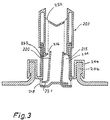
plate 137. - FIGURE 3 shows a modified form of the dosage assembly of FIGURE 2. The main difference compared to the design shown in FIGURE 2 is that the plunger is not retained in its start position by means of capillarity during the filling of the timer chamber. Instead, the
plunger 220 tilts at the moment thetimer chamber 215 is filled. - FIGURE 4 illustrates a third embodiment of a
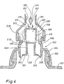
dosage assembly 303 on acontainer 301, comprising astopper 304 sealingly joined to theneck 302 of the container, and a lowercylindrical part 305 connected to an upper cup-shapedpart 307 by means of aconical part 308 and a number ofribs 306. The open end of the cup-shapedpart 307 faces down towards the bottom of thecylindrical part 305 and forms atimer chamber 315. Thetimer chamber 315 is provided with acentral timer aperture 316 in alower wall 317 and a number offeed openings 318 at the free end of acylindrical wall 309. A cup-shapedplunger 320 is sealingly and movably mounted in the cup-shapedpart 307, with the open end of theplunger 320 facing the same direction as the open end of the cup-shapedpart 307. Theplunger 320 has a radially outwardly extendingflange 321 terminating in a number ofcontrol fingers 322 for control and support by the inner surface of thecylindrical part 305. - A substantially cup-shaped
cap 328 is in threaded engagement with thestopper 304 surrounding the upper, cup-shapedpart 307 and theribs 306 of the stopper, to form apassageway 319 around the cup-shapedpart 307. The upper end of thecap 328 is provided with anoutlet 332 defined by anupper outlet passageway 333 and a torpedo-shapedbody 335 connected to the passageway by means ofribs 334. The torpedo-shapedbody 335 sealingly abuts acircular lip 336 around thetimer aperture 316 by means of screwing thecap 328 down for altering the effective size of the timer aperture. - When the container is tilted or turned through 180°, fluid flows out into the
timer chamber 315 viainlet openings 325 between thecontrol fingers 322 of theplunger 320, acircular chamber 326 surrounding the plunger, and thefeed openings 318. Simultaneously fluid flows from thechamber 326 into thepassageway 319 and towards theoutlet opening 332. - The
plunger 320 moves forward owing to the prevailing pressure and displaces fluid from thetimer chamber 315, and after a relatively short travel thewall 310 and the cylindrical side walls of theplunger 320 slide past theopenings 318 and close them off. At the same time, fluid flows through thecircular chamber 326 and thepassageway 319 directly out through theoutlet opening 332 and this continues until theflange 321 of theplunger 320 eventually abuts theconical part 308, thus preventing further fluid flow through the dosage assembly. In the final position the end of theplunger 320 substantially abuts thelower wall 317 of the cup-shapedpart 307 so that thetimer chamber 315 is substantially empty. - Due to gravity, the
plunger 320 immediately drops back to the position of FIGURE 4 and is ready for a new dosing process, when thecontainer 301 anddosage assembly 303 is returned to its vertical position. - FIGURE 5 illustrates a fourth embodiment of a
container 401 withdosage assembly 403 comprising astopper 404 in tight sealing engagement with theneck 402 of thecontainer 401. Thestopper 404 has acylindrical part 408, which faces theinterior 419 of the container and terminates in an inwardly extendingflange 406, and an outwardly extendingthread 407, the latter being in sealing, threaded engagement with acap 428. Thecap 428 has an uppercylindrical part 413 extending towards the interior 419 of the container, the upper end of which forms anoutlet opening 432 and the lower end of which is provided with a number of radially extendingthroughflow openings 409. At its lower end, below theopenings 409, the uppercylindrical part 413 changes into a smaller, lowercylindrical part 411 via aconical part 410, with the lower part 41 terminating in a cone-shapedpart 412. - A
cylindrical plunger 420 having an internal lowerconical flange 421 corresponding in shape to theconical part 410 and radially outwardly extendingcontrol fingers 422 is located in the vicinity of the lowercylindrical part 411 of thecap 428 to form atimer chamber 415. The cylindrical part of theplunger 420 has an inner diameter substantially corresponding to the outer diameter of the uppercylindrical part 413 of thecap 428. Theflange 421 has an inner diameter substantially corresponding to the outer diameter of the lowercylindrical part 411 of thecap 428. - In the start position of the plunger, as shown in FIGURE 5, a
feed opening 418 is provided between theconical flange 421 of theplunger 420 and the cone-shapedpart 412 of thecap 428. Timer apertures 416 (not shown) are provided between thethroughflow openings 409, extending a short distance downwards on theconical part 410 of thecap 428, and thecylindrical part 423 of theplunger 420, extending a short distance upwards on the uppercylindrical part 413 of thecap 428. - When the container is tilted or turned through 180°, the timer chamber is substantially momentarily filled with fluid. The
plunger 420 moves outwards and simultaneously, thetimer chamber 415 empties. The fluid flows around theplunger 420, through thethroughflow openings 409 and forward through thepassageway 417 to theoutlet opening 432. When the timer chamber is emptied, theplunger 420 reaches a final position where itsflange 421 sealingly abuts theconical part 410. At the same time the upper end of thecylindrical part 423 sealingly abuts the uppercylindrical part 413 of thecap 428 directly above thethroughflow openings 409. Thus the flow of fluid through the dosage assembly is blocked. - The amount of fluid delivered is adjusted by means of turning the
cap 428 with respect to thestopper 404 thus altering the travel of theplunger 420 from its start position to its final position, simultaneously changing the effective size of thethroughflow openings 409. - All parts of the dosage assembly are manufactured from injection moulded plastics material. The cap can, for example, be made from polyethylene (LD), the stopper from polypropylene and the plunger from a thermosetting plastics material, such as urea formaldehyde or melanine or optionally from a filled thermoplast, such as BaSO₄-filled polyethylene.
- The invention can be varied in many ways without thus deviating from the scope of the invention. The cap can, for example, be non-adjustably connected with the stopper and optionally be an integral part thereof.
Claims (15)
- A dosage-metering assembly (3, 103, 203, 303, 403) for a fluid container, which has a neck (2, 102, 202, 302, 402) with an opening through which fluid is dispensed when the container is inverted, comprising a stopper member (4, 104, 204, 304, 404) which is mounted on the neck of the container and which has an outlet portion provided with an outlet opening (32, 132, 232, 332, 432) for the outflow of fluid from the container, a timer chamber (15, 115, 215, 315, 415) formed with an annular wall (10, 106, 206, 309, 411) and a plunger (20, 120, 220, 320, 420) formed separately from the stopper, the plunger being movable with respect to the annular wall of the timer chamber under gravity from a start position to an end position when the container is inverted, a feed opening (18, 118, 218, 318, 418) into the timer chamber being included providing fluid communication between the timer chamber and the container whereby fluid feeds into the timer chamber (15, 115, 215, 315, 415) characterised in that the plunger (20, 120, 220, 320, 420) has a timer flange or wall (21, 121, 221, 310, 421) which affords a wall of the timer chamber and which extends radially with regard to the annular wall (10, 106, 206, 309, 411) of the timer chamber and is in slidable sealing relationship therewith so as to sweep through a predetermined volume defined from the start position to the end position of the plunger, and the said volume constitutes the timer chamber (15, 115, 215, 315, 415) which is in fluid communication at one end with a passageway (17, 117, 217, 319, 417) of the stopper member via a restricted timer aperture (16, 116, 216, 316, 416), the said passageway being connected to the outlet opening, and in that the feed opening (18, 118, 218, 318, 418) at another end of the timer chamber feeds fluid from the container to the timer chamber (15, 115, 215, 315, 415) when the container is inverted, and in that another opening (25, 110, 325 and 406', 420) formed in the stopper wall or between the stopper wall and the timer flange or wall also feeds fluid into the passageway (17, 117, 217, 319, 417) of the stopper member and thus to the outlet opening (32, 132, 232, 332, 432) when the container is inverted, the feed opening (18, 118, 218, 318, 418) being cut off by the timer flange or wall (21, 121, 221, 310, 421) of the plunger when it moves past the feed opening a predetermined time after the container is inverted, the timer flange thereby cutting off further flow of fluid from the feed opening (18, 118, 218, 318, 418) into the timer chamber after the predetermined time from the start position, the timer chamber being emptied of fluid by the plunger, whereupon the flow of fluid from the passageway (17, 117, 217, 319, 417) to the outlet opening (32, 132, 232, 332, 432) is cut off by the plunger.
- An assembly as claimed in Claim 1, characterised in that the annular wall (10) of the dosage-metering portion of the stopper member is located radially outwardly of the timer chamber, and an inner annular wall (11) is disposed radially inwardly of the timer chamber, the inner annular wall extending concentrically and in parallel with the first annular wall, and an aperture (16) is provided in the inner annular wall near the end portion of the plunger communicating into the outlet passageway (17) of the stopper member for fluid flow from the timer chamber into the outlet passage as the plunger (20) moves toward its end position.
- An assembly as claimed in Claim 2, characterised in that the plunger (10) has a cup shape formed with a cylindrical skirt (24) and a bottom wall (23), the cylindrical skirt (24) being in slidable engagement with the inner annular wall (11) and having the timer flange (21) at its forward end in slidable engagement between the inner annular wall (11) and the first annular wall (10), the timer chamber (15) thereby being defined as an annular space between the two annular walls.
- An assembly as claimed in Claim 3, characterised in that the plunger (20) has inlet openings (25) in the cylindrical skirt (24) near the bottom wall (23) for secondary flow of fluid on the inside of the inner annular wall into the outlet passage (12, 32) of the stopper member, the inlet openings (25) and the secondary fluid flow being cut off by the inner annular wall (11) as the plunger moves toward its end position.
- An assembly as claimed in any preceding Claim, characterised by a closure cap (28, 128, 328, 428, 547) mounted on the outlet portion of the stopper member for closing the outlet passage (32, 132, 332, 432, 532).
- An assembly as claimed in Claim 5, characterised in that the closure cap (28, 128, 328, 428, 547) has an exit opening (32, 132, 332, 432, 548) for the outflow of fluid from the outlet passage of the stopper member, and includes means for adjusting the fluid flow through the said opening.
- An assembly as claimed in Claim 6, characterised in that the stopper member includes a rod-shaped body (13) aligned on the central axis with one end (37) extending through the outlet passage towards the exit opening (32) of the closure cap (28), the closure cap having engagement means (30) engaging the outlet portion (14) of the stopper member (3) for adjustably displacing the closure cap so that the exit opening of the closure cap is movable from a fully-opened position remote from the end of the rod-shaped body to a closed position in which the exit opening is blocked by the end of the rod-shaped body.
- An assembly as claimed in Claim 1, characterised in that the plunger (120, 220) has a tubular shape formed with a tubular portion located radially inwardly from the annular wall (106) and has the timer flange (121, 521) at its rearward end in slidable sealing engagement with the annular wall, the timer chamber (115, 215) thereby being defined as an annular space between the annular wall and the tubular portion and the timer flange of the plunger.
- An assembly as claimed in Claim 8, characterised by a closure cap (128) mounted on the outlet portion of the stopper member having an exit opening (132) at its forward end and a rearward flange (135) at its rearward end extending radially inwardly towards the tubular portion (120) of the plunger, the rearward flange (135) guiding the tubular portion and providing an abutment surface for the end position of the timer flange (121) of the plunger, the closure cap further having engagement means (134) engaging the outlet portion of the stopper member for adjustably displacing the closure cap along the central axis such that the rearward flange (135) defines an adjustable end position for the movement of the plunger.
- An assembly as claimed in Claim 1, characterised in that the plunger (320) has an inverted cup shape formed with a cylindrical body and the timer flange as a forward wall (310) at its forward end, and the dosage-metering portion is formed with a cylindrical portion (309) receiving the cylindrical body (320) of the plunger in slidable sealing engagement and a terminal wall (317) defining the end position of the plunger provided with an opening (316) as the outlet passage, the timer chamber thereby being defined as a cylindrical space (315) between the timer flange (321) at the forward end of the cup-shaped plunger (320) and the cylindrical portion (309) of the dosage-metering portion.
- An assembly as claimed in Claim 10, characterised in that the plunger (320) has a rearward flange (321) and guide fingers (322) at its rearward end which extend to side wall portions (305) of the stopper member, the guide fingers (322) allowing a secondary flow of fluid around the guide fingers and through the passageway (319) around the cylindrical portion (309) of the dosage-metering portion, the passageway (319) being closed off by the rearward flange (321) at the end position of the plunger.
- An assembly as claimed in Claim 10, characterised by a closure cap (328) mounted on the outlet portion of the stopper member having a forward opening (332) with a plug body (335) centred therein and engagement means (318) engaging the outlet portion of the stopper member for adjustably displacing the closure cap (328) along the central axis such that the plug body (335) is movable from a fully-opened position remote from the cylindrical portion to a closure position in which the opening in the cylindrical portion is blocked by the plug body.
- An assembly as claimed in Claim 1, characterised in that the dosage-metering portion of the stopper member includes a forward cylindrical portion (413) and a rearward cylindrical portion (411) of a lesser radius, both being concentric with the central axis, and a shoulder portion (410) connecting the cylindrical portions, the forward cylindrical portion (413) having throughflow openings (409) therein communicating into an inner bore defining the outlet passage, the plunger (420) being formed with a cylindrical wall (423) in slidable sealing relationship with the forward cylindrical portion (413) and with the timer flange (421) at its rearward end extending radially inwardly to the rearward cylindrical portion (411), the timer chamber (415) thereby being defined as an annular space between the rearward cylindrical portion (411), the shoulder portion (410), and the cylindrical wall (423) and timer flange (421) of the plunger, a feed opening (418) to the timer chamber (415) being provided between the flange (421) and the wall (411) at the start position of the plunger, the shoulder portion (410) being abutted by the timer flange (421) to define the end position of the plunger at which the cylindrical wall of the plunger cuts off the throughflow openings (409).
- An assembly as claimed in Claim 13, characterised in that the stopper member has a first part (428) supporting the cylindrical and shoulder portions (413, 409, 410, 411), a second part (403) mounted on the neck (402) of the container, and engagement means (407) engaging the first part (428) with the second part (403) for adjustably displacing the first part along the central axis so that the shoulder portion (410) defines an adjustable end portion for the movement of the plunger.
- An assembly as claimed in Claim 13, or Claim 14 characterised in that the plunger (420) has guide fingers (422) at its rearward end which extend to side wall portions (408) of the stopper member, the guide fingers (422) allowing a secondary flow of fluid around the guide fingers and through the throughflow openings (409) in the forward cylindrical portion of the dosage-metering portion.
Applications Claiming Priority (4)
| Application Number | Priority Date | Filing Date | Title |
|---|---|---|---|
| DK203088A DK203088D0 (en) | 1988-04-13 | 1988-04-13 | DOSAGE CONTAINERS |
| DK2030/88 | 1988-04-13 | ||
| DK1582/89 | 1989-03-31 | ||
| DK158289A DK158289A (en) | 1988-04-13 | 1989-03-31 | BASKET WITH DOSING DEVICE |
Publications (3)
| Publication Number | Publication Date |
|---|---|
| EP0337778A2 EP0337778A2 (en) | 1989-10-18 |
| EP0337778A3 EP0337778A3 (en) | 1991-05-15 |
| EP0337778B1 true EP0337778B1 (en) | 1996-03-13 |
Family
ID=26065921
Family Applications (1)
| Application Number | Title | Priority Date | Filing Date |
|---|---|---|---|
| EP89303656A Expired - Lifetime EP0337778B1 (en) | 1988-04-13 | 1989-04-13 | Fluid container with dosage assembly |
Country Status (15)
| Country | Link |
|---|---|
| US (1) | US4946080A (en) |
| EP (1) | EP0337778B1 (en) |
| JP (1) | JPH0245057A (en) |
| AR (1) | AR243677A1 (en) |
| AT (1) | ATE135461T1 (en) |
| AU (1) | AU628809B2 (en) |
| BR (1) | BR8901764A (en) |
| CA (1) | CA1332926C (en) |
| DE (1) | DE68925917T2 (en) |
| DK (1) | DK158289A (en) |
| HK (1) | HK1007596A1 (en) |
| MX (1) | MX173740B (en) |
| MY (1) | MY103996A (en) |
| NO (1) | NO178618C (en) |
| NZ (1) | NZ228723A (en) |
Families Citing this family (33)
| Publication number | Priority date | Publication date | Assignee | Title |
|---|---|---|---|---|
| IT1241436B (en) * | 1990-03-12 | 1994-01-17 | Unilever Nv | CLOSING AND DISPENSING DEVICE OF LIQUID PRODUCT FROM A CONTAINER. |
| GB9026606D0 (en) * | 1990-12-06 | 1991-01-23 | Courtaulds Packaging Ltd | Dose dispenser |
| US5975369A (en) | 1997-06-05 | 1999-11-02 | Erie County Plastics Corporation | Resealable pushable container closure and cover therefor |
| US7107783B2 (en) * | 1997-09-19 | 2006-09-19 | Advanced Porcus Technologies, Llc | Self-cooling containers for liquids |
| US20040173556A1 (en) * | 1997-09-19 | 2004-09-09 | Smolko Daniel D. | Vented closures for containers |
| US6398048B1 (en) * | 1997-09-19 | 2002-06-04 | Gregory Kevorkian | Vented beverage container |
| FR2789054B3 (en) * | 1999-02-02 | 2001-03-16 | 3 D Dev | DEVICE FOR DOSING A LIQUID CONTAINED IN A NECK CONTAINER AND INVIOLABILITY OF THIS CONTAINER |
| US6062441A (en) * | 1999-07-15 | 2000-05-16 | Rxi Plastics, Inc. | Two-piece dispensing closure |
| GB0001119D0 (en) * | 2000-01-18 | 2000-03-08 | Wass Anthony C L | Improved liquid dosing device |
| US6338425B1 (en) * | 2000-10-05 | 2002-01-15 | Courtesy Corporation | Dispensing closure |
| US6997358B2 (en) | 2001-09-12 | 2006-02-14 | Anthony Charles Lammond Wass | Liquid dosing device |
| ITGE20030080A1 (en) * | 2003-10-15 | 2005-04-16 | Invat Srl | CAP FOR CONTAINERS WITH SEALS FILLABLE WITH LA |
| US20080134780A1 (en) * | 2006-12-07 | 2008-06-12 | Michael Micheli | Liquid measuring device and method of using same |
| US9433960B2 (en) * | 2008-09-01 | 2016-09-06 | Rieke Corporation | Liquid dosing devices |
| DE102008060773A1 (en) * | 2008-12-05 | 2010-06-10 | Sartorius Stedim Biotech Gmbh | Closure for a container |
| DE102010019691A1 (en) * | 2010-05-07 | 2011-11-10 | Sartorius Stedim Biotech Gmbh | Valve for a container |
| EP2444782B1 (en) | 2010-10-21 | 2019-01-16 | The Procter and Gamble Company | Liquid dosing apparatus |
| EP2637800B1 (en) * | 2010-11-09 | 2015-08-26 | Unilever N.V. | Dosing cap for container |
| ES2552249T1 (en) * | 2012-04-17 | 2015-11-26 | The Procter & Gamble Company | Liquid dosing device |
| BR112015023004A8 (en) | 2013-03-15 | 2019-12-03 | Diversey Inc | adjustable distributor cap |
| USD746137S1 (en) | 2013-11-15 | 2015-12-29 | Diversey, Inc. | Dosing cap |
| CH709451A1 (en) | 2014-03-31 | 2015-10-15 | Capartis Ag | Metering device for a liquid feed from a container or hose with nozzle. |
| WO2016155757A2 (en) | 2015-03-27 | 2016-10-06 | Capartis Ag | Dosing device for a liquid supply comprising a neck |
| US10159998B2 (en) | 2015-06-29 | 2018-12-25 | Silgan Dispensing Systems Slatersville, Llc | Measured dose dispensers and methods of using the same |
| US9555426B2 (en) * | 2015-06-29 | 2017-01-31 | Westrock Slatersville, Llc | Measured dose dispensers and methods of using the same |
| US10471452B2 (en) | 2015-06-29 | 2019-11-12 | Silgan Dispensing Systems Slatersville Llc | Measured dose dispensers and methods of using the same |
| EP3314219B1 (en) * | 2015-06-29 | 2022-01-05 | Silgan Dispensing Systems Netherlands B.V. | Measured dose dispenser |
| EP3315922B1 (en) | 2016-10-25 | 2020-01-08 | The Procter & Gamble Company | Liquid dosing apparatus |
| EP3315923B1 (en) | 2016-10-25 | 2020-11-25 | The Procter & Gamble Company | Liquid dosing apparatus |
| EP3315924B1 (en) * | 2016-10-25 | 2021-07-14 | The Procter & Gamble Company | Liquid dosing apparatus |
| WO2021051058A1 (en) * | 2019-09-13 | 2021-03-18 | Rieke Llc | Valve and gasket tolerant to pressure-differentials |
| US11117719B2 (en) * | 2020-01-09 | 2021-09-14 | Troy McConnell | Selective flow cohesive streaming caps |
| US11885660B2 (en) * | 2021-04-20 | 2024-01-30 | Flexpenser Ab | Dosing applicator for medical and non-medical containers |
Family Cites Families (9)
| Publication number | Priority date | Publication date | Assignee | Title |
|---|---|---|---|---|
| US2141870A (en) * | 1937-09-09 | 1938-12-27 | Koukal Louis | Combined bottle stopper and liquid measuring device |
| US3146923A (en) * | 1963-10-09 | 1964-09-01 | Story F Chappell | Measured-dose slide valve dispenser |
| US3567079A (en) * | 1968-08-08 | 1971-03-02 | Cleone H Weigand | Dispenser container with metering neck |
| US4383623A (en) * | 1981-03-17 | 1983-05-17 | Ethyl Products Company | Dispensing closure with stationary axial plug |
| US4407435A (en) * | 1982-01-21 | 1983-10-04 | Harmon James V | Dispenser for pouring measured quantities of a liquid from a container |
| DE3308013A1 (en) * | 1983-03-07 | 1984-09-13 | Henkel KGaA, 4000 Düsseldorf | DOSING DEVICE |
| DE3525814A1 (en) * | 1985-07-19 | 1987-01-22 | Alkohol Handelskontor Ahk | DOSING CAP |
| BE905791A (en) * | 1986-11-19 | 1987-03-16 | Lynes Holding Sa | POURING CAP. |
| US4811871A (en) * | 1986-12-17 | 1989-03-14 | The English Glass Company Limited | Liquid dosing device |
-
1989
- 1989-03-31 DK DK158289A patent/DK158289A/en not_active Application Discontinuation
- 1989-04-12 CA CA000596415A patent/CA1332926C/en not_active Expired - Fee Related
- 1989-04-12 AU AU32751/89A patent/AU628809B2/en not_active Ceased
- 1989-04-12 MY MYPI89000462A patent/MY103996A/en unknown
- 1989-04-12 NO NO891510A patent/NO178618C/en unknown
- 1989-04-12 NZ NZ228723A patent/NZ228723A/en unknown
- 1989-04-13 DE DE68925917T patent/DE68925917T2/en not_active Expired - Fee Related
- 1989-04-13 JP JP1094283A patent/JPH0245057A/en active Pending
- 1989-04-13 AR AR89313667A patent/AR243677A1/en active
- 1989-04-13 MX MX015660A patent/MX173740B/en unknown
- 1989-04-13 BR BR898901764A patent/BR8901764A/en not_active IP Right Cessation
- 1989-04-13 EP EP89303656A patent/EP0337778B1/en not_active Expired - Lifetime
- 1989-04-13 AT AT89303656T patent/ATE135461T1/en not_active IP Right Cessation
- 1989-04-19 US US07/340,184 patent/US4946080A/en not_active Expired - Fee Related
-
1998
- 1998-06-25 HK HK98106723A patent/HK1007596A1/en not_active IP Right Cessation
Also Published As
| Publication number | Publication date |
|---|---|
| BR8901764A (en) | 1989-11-28 |
| MY103996A (en) | 1993-10-30 |
| DE68925917T2 (en) | 1996-10-31 |
| HK1007596A1 (en) | 1999-04-16 |
| NO178618C (en) | 1996-05-02 |
| US4946080A (en) | 1990-08-07 |
| AU628809B2 (en) | 1992-09-24 |
| DE68925917D1 (en) | 1996-04-18 |
| NO891510D0 (en) | 1989-04-12 |
| EP0337778A2 (en) | 1989-10-18 |
| AU3275189A (en) | 1989-10-19 |
| CA1332926C (en) | 1994-11-08 |
| ATE135461T1 (en) | 1996-03-15 |
| DK158289D0 (en) | 1989-03-31 |
| JPH0245057A (en) | 1990-02-15 |
| MX173740B (en) | 1994-03-25 |
| NO891510L (en) | 1989-10-16 |
| EP0337778A3 (en) | 1991-05-15 |
| NZ228723A (en) | 1991-08-27 |
| AR243677A1 (en) | 1993-08-31 |
| NO178618B (en) | 1996-01-22 |
| DK158289A (en) | 1989-10-14 |
Similar Documents
| Publication | Publication Date | Title |
|---|---|---|
| EP0337778B1 (en) | Fluid container with dosage assembly | |
| US4728011A (en) | Metering stopper | |
| US4541552A (en) | Apparatus for metering liquids or semiliquids | |
| US4007858A (en) | Squeeze-bottle-type powder dispenser | |
| US4406313A (en) | Method and apparatus for filling discrete drums with a liquid | |
| US5584420A (en) | Reusable and accurately pre-measured liquid dispenser | |
| US4407435A (en) | Dispenser for pouring measured quantities of a liquid from a container | |
| US4438869A (en) | Dosing device with ball valve and operating method | |
| US3161330A (en) | Aerosol dispenser having a wall-surrounded valve actuator button | |
| WO2019150106A1 (en) | Improvement to a dosing apparatus and a container | |
| CN109073435B (en) | Dosing device and container | |
| WO2007094660A1 (en) | Dosing device for a fluid | |
| US10138050B2 (en) | Dispensing valve incorporating a metering valve | |
| US5407104A (en) | Dosing device for liquids | |
| EP0132875B1 (en) | Pouring adapter insert | |
| US5119975A (en) | Drop volume dispensing closure | |
| US4684046A (en) | Unit dose liquid dispenser having precise dosage capabilities | |
| JP2003237864A (en) | Device for packaging and dose-dispensing of liquid product | |
| US3478934A (en) | Metering apparatus | |
| EP3384249B1 (en) | Dosing apparatus and a container | |
| AU2015218380B2 (en) | Dispensing valve incorporating a metering valve | |
| US4449651A (en) | Tubular metering or dosing mechanism for dispensing liquid from a container in successive quantums of uniform volume | |
| JPS6177720A (en) | Pipe-type and two chamber system quantity regulator for fluid | |
| JPH06508931A (en) | quantitative dispenser | |
| US4881667A (en) | Siphon dispenser |
Legal Events
| Date | Code | Title | Description |
|---|---|---|---|
| PUAI | Public reference made under article 153(3) epc to a published international application that has entered the european phase |
Free format text: ORIGINAL CODE: 0009012 |
|
| AK | Designated contracting states |
Kind code of ref document: A2 Designated state(s): AT BE CH DE ES FR GB GR IT LI LU NL SE |
|
| PUAL | Search report despatched |
Free format text: ORIGINAL CODE: 0009013 |
|
| AK | Designated contracting states |
Kind code of ref document: A3 Designated state(s): AT BE CH DE ES FR GB GR IT LI LU NL SE |
|
| 17P | Request for examination filed |
Effective date: 19911104 |
|
| 17Q | First examination report despatched |
Effective date: 19930513 |
|
| GRAH | Despatch of communication of intention to grant a patent |
Free format text: ORIGINAL CODE: EPIDOS IGRA |
|
| GRAA | (expected) grant |
Free format text: ORIGINAL CODE: 0009210 |
|
| AK | Designated contracting states |
Kind code of ref document: B1 Designated state(s): AT BE CH DE ES FR GB GR IT LI LU NL SE |
|
| PG25 | Lapsed in a contracting state [announced via postgrant information from national office to epo] |
Ref country code: NL Free format text: LAPSE BECAUSE OF FAILURE TO SUBMIT A TRANSLATION OF THE DESCRIPTION OR TO PAY THE FEE WITHIN THE PRESCRIBED TIME-LIMIT Effective date: 19960313 Ref country code: LI Free format text: LAPSE BECAUSE OF FAILURE TO SUBMIT A TRANSLATION OF THE DESCRIPTION OR TO PAY THE FEE WITHIN THE PRESCRIBED TIME-LIMIT Effective date: 19960313 Ref country code: GR Free format text: LAPSE BECAUSE OF FAILURE TO SUBMIT A TRANSLATION OF THE DESCRIPTION OR TO PAY THE FEE WITHIN THE PRESCRIBED TIME-LIMIT Effective date: 19960313 Ref country code: ES Free format text: THE PATENT HAS BEEN ANNULLED BY A DECISION OF A NATIONAL AUTHORITY Effective date: 19960313 Ref country code: CH Free format text: LAPSE BECAUSE OF FAILURE TO SUBMIT A TRANSLATION OF THE DESCRIPTION OR TO PAY THE FEE WITHIN THE PRESCRIBED TIME-LIMIT Effective date: 19960313 Ref country code: BE Effective date: 19960313 Ref country code: AT Effective date: 19960313 |
|
| REF | Corresponds to: |
Ref document number: 135461 Country of ref document: AT Date of ref document: 19960315 Kind code of ref document: T |
|
| REF | Corresponds to: |
Ref document number: 68925917 Country of ref document: DE Date of ref document: 19960418 |
|
| PG25 | Lapsed in a contracting state [announced via postgrant information from national office to epo] |
Ref country code: LU Free format text: LAPSE BECAUSE OF NON-PAYMENT OF DUE FEES Effective date: 19960430 |
|
| ITF | It: translation for a ep patent filed |
Owner name: BARZANO' E ZANARDO ROMA S.P.A. |
|
| PG25 | Lapsed in a contracting state [announced via postgrant information from national office to epo] |
Ref country code: SE Effective date: 19960613 |
|
| ET | Fr: translation filed | ||
| NLV1 | Nl: lapsed or annulled due to failure to fulfill the requirements of art. 29p and 29m of the patents act | ||
| REG | Reference to a national code |
Ref country code: CH Ref legal event code: PL |
|
| PLBE | No opposition filed within time limit |
Free format text: ORIGINAL CODE: 0009261 |
|
| STAA | Information on the status of an ep patent application or granted ep patent |
Free format text: STATUS: NO OPPOSITION FILED WITHIN TIME LIMIT |
|
| 26N | No opposition filed | ||
| PGFP | Annual fee paid to national office [announced via postgrant information from national office to epo] |
Ref country code: DE Payment date: 19980323 Year of fee payment: 10 |
|
| PGFP | Annual fee paid to national office [announced via postgrant information from national office to epo] |
Ref country code: GB Payment date: 19980324 Year of fee payment: 10 |
|
| PGFP | Annual fee paid to national office [announced via postgrant information from national office to epo] |
Ref country code: FR Payment date: 19980428 Year of fee payment: 10 |
|
| PG25 | Lapsed in a contracting state [announced via postgrant information from national office to epo] |
Ref country code: GB Free format text: LAPSE BECAUSE OF NON-PAYMENT OF DUE FEES Effective date: 19990413 |
|
| GBPC | Gb: european patent ceased through non-payment of renewal fee |
Effective date: 19990413 |
|
| PG25 | Lapsed in a contracting state [announced via postgrant information from national office to epo] |
Ref country code: FR Free format text: LAPSE BECAUSE OF NON-PAYMENT OF DUE FEES Effective date: 19991231 |
|
| REG | Reference to a national code |
Ref country code: FR Ref legal event code: ST |
|
| PG25 | Lapsed in a contracting state [announced via postgrant information from national office to epo] |
Ref country code: DE Free format text: LAPSE BECAUSE OF NON-PAYMENT OF DUE FEES Effective date: 20000201 |
|
| PG25 | Lapsed in a contracting state [announced via postgrant information from national office to epo] |
Ref country code: IT Free format text: LAPSE BECAUSE OF NON-PAYMENT OF DUE FEES;WARNING: LAPSES OF ITALIAN PATENTS WITH EFFECTIVE DATE BEFORE 2007 MAY HAVE OCCURRED AT ANY TIME BEFORE 2007. THE CORRECT EFFECTIVE DATE MAY BE DIFFERENT FROM THE ONE RECORDED. Effective date: 20050413 |