EP0337439A2 - Fixed cylinder type radial piston pump with volume control apparatus - Google Patents
Fixed cylinder type radial piston pump with volume control apparatus Download PDFInfo
- Publication number
- EP0337439A2 EP0337439A2 EP89106542A EP89106542A EP0337439A2 EP 0337439 A2 EP0337439 A2 EP 0337439A2 EP 89106542 A EP89106542 A EP 89106542A EP 89106542 A EP89106542 A EP 89106542A EP 0337439 A2 EP0337439 A2 EP 0337439A2
- Authority
- EP
- European Patent Office
- Prior art keywords
- pump
- fixed cylinder
- volume control
- radial piston
- cylinder type
- Prior art date
- Legal status (The legal status is an assumption and is not a legal conclusion. Google has not performed a legal analysis and makes no representation as to the accuracy of the status listed.)
- Withdrawn
Links
Images


Classifications
-
- F—MECHANICAL ENGINEERING; LIGHTING; HEATING; WEAPONS; BLASTING
- F04—POSITIVE - DISPLACEMENT MACHINES FOR LIQUIDS; PUMPS FOR LIQUIDS OR ELASTIC FLUIDS
- F04B—POSITIVE-DISPLACEMENT MACHINES FOR LIQUIDS; PUMPS
- F04B49/00—Control, e.g. of pump delivery, or pump pressure of, or safety measures for, machines, pumps, or pumping installations, not otherwise provided for, or of interest apart from, groups F04B1/00 - F04B47/00
- F04B49/22—Control, e.g. of pump delivery, or pump pressure of, or safety measures for, machines, pumps, or pumping installations, not otherwise provided for, or of interest apart from, groups F04B1/00 - F04B47/00 by means of valves
- F04B49/225—Control, e.g. of pump delivery, or pump pressure of, or safety measures for, machines, pumps, or pumping installations, not otherwise provided for, or of interest apart from, groups F04B1/00 - F04B47/00 by means of valves with throttling valves or valves varying the pump inlet opening or the outlet opening
Definitions
- the present invention relates to a volume control apparatus of fixed cylinder type radial piston pump.
- the rotating cylinder type radial piston pump is constructed such that radially reciprocable pistons are disposed in a cylinder rotated by a pump driving force and are reciprocated as being guided along an inside circumference of an eccentric cam ring to obtain a pump action, so that it is difficult to get a variable volume construction by regulating an eccentric amount of the cam ring.
- an eccentricity adjusting mechanism has to be further provided to the cam ring witha large diameter, causing a pump dimension and weight increase and a bad responsibility of volume control.
- the fixed cylinder type radial piston pump is constructed such that radially reciprocable pistons are disposed in a fixed cylinder and are reciprocated by an eccentric cam rotated by a pump driving force to obtain a pump action, so that the above-mentioned problem does not arise but pump construction becomes complex to get an eccentric amount of the eccentric cam variable.
- an object of the present invention is to provide a fixed cylinder type radial piston pump in which volume control is possible without regulating the eccentric amount of the eccentric cam.
- a specific object of the present invention is to provide a volume control apparatus of fixed cylinder type radial piston pump.
- a fixed cylinder type radial piston pump with volume control apparatus comprising: a pump portion including suction and delivery systems, said pump portion carrying out a pump action by pump driving force of a pump drive shaft; a fixed cylinder provided in said pump portion, in which a plurality of pistons are slidably disposed, said plurality of pistons being radially reciprocable in said fixed cylinder to suck a fluid from a suction passage and discharge said fluid to a delivery passage; an eccentric cam installed on said pump drive shaft and rotated by a pump driving force of said pump drive shaft, said eccentric cam guiding said plurality of pistons slidably disposed in said fixed cylinder; and an aperture means for carrying out opening control of said suction passage.
- a fixed cylinder type radial piston pump 1 includes a pump body 2 in which a pump drive shaft 10 is rotatably supported by bearings 4, 6 and 8.
- An eccentric portion 10a is installed on the pump drive shaft 10 thereby to pivotally support an eccentric cam 12.
- a plurality of pistons 14 are disposed each being radially slidable in the pump body 2.
- Each of the pistons 14 touches an outside circumference of the eccentric cam 12 by force of a spring 16 and incorporates a suction valve 18.
- a delivery valve 20 is provided in the pump body 2.
- the radial piston pump 1 thus constructed operates as follows: When the drive shaft 10 is rotated by pump driving force, the eccentric cam 12 radially reciprocates each of the pistons 14. While each of the pistons 14 strokes radially inwardly, the suction valve 18 is opened thereby to suck a fluid from a suction passage 22 and a suction port 24 into a pump chamber 26. While each of the pistons 14 strokes radially outwardly, the suction valve 18 is closed to generate a pressure in the pump chamber 26, thereby to open the delivery valve 20 and discharge the fluid from the chamber 26 to a delivery port 28 and a delivery passage 30 therethrough. A check valve 32, an accumulator 34 and a relief valve 36 are provided in the delivery passage 30.
- the fluid flowing in the passage 30 comes to the accumulator 34 through the check valve 32, wherein fluid pressure is increased to form a line pressure P L for controlling a hydraulic apparatus (not shown). If the line pressure P L is too high, the relief valve 36 is opened to prevent a pump circuit from being damaged.
- a variable aperture 38 is inserted in the suction passage 22 thereby to permit volume control of the pump 1.
- the variable aperture 38 is of the rotary type capable of controlling an opening of the suction passage 22 and its rotational position is regulated by a step motor 40.
- the step motor 40 opens completely the variable aperture 38 at a drive step number 0 and minimally opens it at a drive step number Max.
- the motor 40 is controlled through an amplifier 44 by a microcomputer 42 to which is input a signal L from a limit switch 46 which is turned on at the minimum opening of the variable aperture 38. Additionally, after converting to a digital signal by an analog-to-digital converter 48, a signal from a pressure sensor 47 for detecting the line pressure P L is input to the computer 42.
- the pressure sensor 47 provides a voltage V to the line pressure P L as shown in Fig. 3, in which P1 and P2 denote lower and upper limits of working line pressure and V1 and V2 output voltages of the sensor 47 with respect to the lower and upper limits.
- an opening pressure P3 of the relief valve 36 is also indicated for reference.
- the microcomputer 42 performs a control program on input informations as mentioned above, thereby to carry out opening control of the suction passage 22, i.e. volume control of the pump 1 by means of the step motor 40.
- the drive step number STEP of the motor 40 is initialized and the variable aperture 38 completely opens the suction passage 22 to set the pump 1 in the maximum discharge (maximum capacity).
- the maximum amount of fluid is discharged in the passage 30, allowing rapid increase of the line pressure P L .
- an output voltage V of the pressure sensor 47 is read to detect a current value of the line pressure P L .
- an aimed drive step number STEP (A) of the step motor 40 is looked up from a table data corresponding to Fig. 3 obtained from the current value of the line pressure P L .
- the table data of the aimed drive step number STEP (A) is such that: If the line pressure P L is less than the lower limit P1, the variable aperture 38 is completely opened to maximize the pump discharge; if the line pressure P L is more than the upper limit P2, the aperture 38 is minimally opened to minimize the pump discharge; and if the line pressure P L falls in a practical range from P1 to P2, the aperture 38 is set to a predetermined opening to appropriately control the pump discharge, thereby for keeping the line pressure P L in the practical range.
- step 53 if it is judged that the limit switch 46 is turned on, the program proceeds to step 54 at which the step number STEP is set to the maximum STEP (Max) thereby to avoid integrating an error of the step number STEP.
- step 55 the current step number STEP is compared with the aimed step number STEP (A). If both are of the same value, the program proceeds to step 56 at which a signal for driving the step motor 40 is provided to keep the variable aperture 38 at a current opening. If the current step number STEP is less than the aimed step number STEP (A) or STEP is more than STEP (A), the program proceeds to step 57 or 58 at which the step number STEP is increased or decreased by one to set it to the aimed step number STEP (A). And at step 56, a signal for driving the step motor 40 is provided as described above.
- the step motor 40 may carry out opening control of the variable aperture 38 to keep the line pressure P L in the practical range from P1 to P2 and allows an approproiate selection of a pump capacity resulting in an energy-saving.
- the pump discharge is indicated by a fully-drawn line in Fig. 4.
- the discharge is reduced as indicated by an one-dot-chain line in Fig. 4 because of decreased opening period of time of the suction valve 18.
- FIG. 5 there is shown another embodiment of the present invention, in which another eccentric portion 10b is installed on the pump drive shaft 10 to rotatably support an eccentric cam 12′ and a pump portion comprising a piston 14′, a spring 16′, a suction valve 18′ and a delivery valve 20′ is added to include two pump portions displaced by a half phase each other.
- the two pump portions have a delivery port 28 and a delivery passage 30 in common and two suction systems separated by an intermediate wall 60.
- One suction system includes, as described above, the suction passage 22 with the variable aperture 38 and the suction port 24 and another a suction passage 22′ and a suction port 24′.
- a gate valve 62 is provided in the suction passage 22′.
- the discharge of a pump portion related to the valve 62 is increased, e.g. the maximum pump discharge can be increased from a characteristic value indicated by a fully-drawn line in Fig. 6 equivalent to that in Fig. 4 to a characteristic value indicated by a one-dot-chain line in Fig. 6. Additionally, it can be continuously decreased up to a characteristic value indicated by a three-dot-chain line by carrying out opening control of the variable aperture 38 with the gate valve 62 opened.
- pump discharge characteristic similar to Fig. 4 can be obtained by carrying out opening control of the variable aperture 38 with the gate valve 62 closed.
- the pump discharge also can be reduced from a characteristic value indicated by the fully-drawn line to that indicated by a two-dot-chain line in Fig. 6 by performing opening control of the variable aperture 38 with the gate valve 62 closed.
- the pump discharge is capable of being continuously controlled from the characteristic value indicated by the one-dot-chain line to that indicated by the two-dot-chain line so that control range is greatly enlarged.
- suction system related to a suction port 24′ is associated with a pump chamber 26′ through a suction check valve 64 as shown in Fig. 7, suction systems of two pump portions can be separated without the intermediate wall 60 as shown in Fig. 5, resulting in reduction of the total length of the pump.
Landscapes
- Engineering & Computer Science (AREA)
- Mechanical Engineering (AREA)
- General Engineering & Computer Science (AREA)
- Reciprocating Pumps (AREA)
- Details Of Reciprocating Pumps (AREA)
- Control Of Positive-Displacement Pumps (AREA)
Abstract
A fixed cylinder type radial piston pump (1) with volume control apparatus is disclosed, in which volume control is possible by means of a variable aperture (38) carrying out opening control of a suction passage (22). For achieving continuous volume control in a large range, the radial piston pump (1) can provide two pump portions separated by an intermediate wall (60) and including a gate valve (62) in the other suction passage (22'). Without installing the intermediate wall (60), it is also possible to separate the two pump portions from each other by using a suction check valve (64).
Description
- The present invention relates to a volume control apparatus of fixed cylinder type radial piston pump.
- As described in "Hydraulic Technique Handbook", p. 257 (Fig. 1 ·36) and p. 259 (Fig. 1·39) published by Nikkan Kogyo Shinbunsha Inc., January 30, 1976, in Japan, there are shown two different kinds of radial piston pumps: one being of the rotating cylinder type and the other of the fixed cylinder type.
- The rotating cylinder type radial piston pump is constructed such that radially reciprocable pistons are disposed in a cylinder rotated by a pump driving force and are reciprocated as being guided along an inside circumference of an eccentric cam ring to obtain a pump action, so that it is difficult to get a variable volume construction by regulating an eccentric amount of the cam ring. To obtain the rotating cylinder type radial piston pump of the variable volume construction, an eccentricity adjusting mechanism has to be further provided to the cam ring witha large diameter, causing a pump dimension and weight increase and a bad responsibility of volume control.
- On the other hand, the fixed cylinder type radial piston pump is constructed such that radially reciprocable pistons are disposed in a fixed cylinder and are reciprocated by an eccentric cam rotated by a pump driving force to obtain a pump action, so that the above-mentioned problem does not arise but pump construction becomes complex to get an eccentric amount of the eccentric cam variable.
- Therefore, an object of the present invention is to provide a fixed cylinder type radial piston pump in which volume control is possible without regulating the eccentric amount of the eccentric cam.
- A specific object of the present invention is to provide a volume control apparatus of fixed cylinder type radial piston pump.
- According to the present invention, there is provided a fixed cylinder type radial piston pump with volume control apparatus, comprising:
a pump portion including suction and delivery systems, said pump portion carrying out a pump action by pump driving force of a pump drive shaft;
a fixed cylinder provided in said pump portion, in which a plurality of pistons are slidably disposed, said plurality of pistons being radially reciprocable in said fixed cylinder to suck a fluid from a suction passage and discharge said fluid to a delivery passage;
an eccentric cam installed on said pump drive shaft and rotated by a pump driving force of said pump drive shaft, said eccentric cam guiding said plurality of pistons slidably disposed in said fixed cylinder; and
an aperture means for carrying out opening control of said suction passage. -
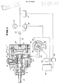
- Fig. 1 is a longitudinal sectional view of an embodiment of a fixed cylinder type radial piston pump with volume control apparatus according to the present invention;
- Fig. 2 is a flow chart showing a control program of a microcomputer;
- Fig. 3 is a diagram showing an output voltage characteristic of a pressure sensor and a motor drive step number of a variable aperture;
- Fig. 4 is a diagram showing a pump discharge characteristic;
- Fig. 5 is a longitudinal sectional view showing another embodiment of a fixed cylinder type radial piston pump according to the present invention;
- Fig. 6 is a diagram showing a pump discharge characteristic of another embodiment of Fig. 5; and
- Fig. 7 is a longitudinal sectional view showing a further embodiment of a fixed cylinder type radial piston pump according to the present invention.
- Referring now to Fig. 1 there is shown an embodiment of the present invention, in which a fixed cylinder type
radial piston pump 1 includes apump body 2 in which apump drive shaft 10 is rotatably supported bybearings eccentric portion 10a is installed on thepump drive shaft 10 thereby to pivotally support aneccentric cam 12. Around theeccentric cam 12, a plurality ofpistons 14 are disposed each being radially slidable in thepump body 2. Each of thepistons 14 touches an outside circumference of theeccentric cam 12 by force of aspring 16 and incorporates asuction valve 18. In series with respect to thesuction valve 18, adelivery valve 20 is provided in thepump body 2. - The
radial piston pump 1 thus constructed operates as follows: When thedrive shaft 10 is rotated by pump driving force, theeccentric cam 12 radially reciprocates each of thepistons 14. While each of thepistons 14 strokes radially inwardly, thesuction valve 18 is opened thereby to suck a fluid from asuction passage 22 and asuction port 24 into apump chamber 26. While each of thepistons 14 strokes radially outwardly, thesuction valve 18 is closed to generate a pressure in thepump chamber 26, thereby to open thedelivery valve 20 and discharge the fluid from thechamber 26 to adelivery port 28 and adelivery passage 30 therethrough. Acheck valve 32, anaccumulator 34 and arelief valve 36 are provided in thedelivery passage 30. The fluid flowing in thepassage 30 comes to theaccumulator 34 through thecheck valve 32, wherein fluid pressure is increased to form a line pressure PL for controlling a hydraulic apparatus (not shown). If the line pressure PL is too high, therelief valve 36 is opened to prevent a pump circuit from being damaged. Avariable aperture 38 is inserted in thesuction passage 22 thereby to permit volume control of thepump 1. Thevariable aperture 38 is of the rotary type capable of controlling an opening of thesuction passage 22 and its rotational position is regulated by astep motor 40. Thestep motor 40 opens completely thevariable aperture 38 at adrive step number 0 and minimally opens it at a drive step number Max. Themotor 40 is controlled through anamplifier 44 by amicrocomputer 42 to which is input a signal L from alimit switch 46 which is turned on at the minimum opening of thevariable aperture 38. Additionally, after converting to a digital signal by an analog-to-digital converter 48, a signal from apressure sensor 47 for detecting the line pressure P L is input to thecomputer 42. Thepressure sensor 47 provides a voltage V to the line pressure P L as shown in Fig. 3, in which P₁ and P₂ denote lower and upper limits of working line pressure and V₁ and V₂ output voltages of thesensor 47 with respect to the lower and upper limits. In Fig. 3, an opening pressure P₃ of therelief valve 36 is also indicated for reference. - Referring to Fig. 2, the
microcomputer 42 performs a control program on input informations as mentioned above, thereby to carry out opening control of thesuction passage 22, i.e. volume control of thepump 1 by means of thestep motor 40. Atstep 50, upon starting thestep motor 40, the drive step number STEP of themotor 40 is initialized and thevariable aperture 38 completely opens thesuction passage 22 to set thepump 1 in the maximum discharge (maximum capacity). Thus, upon starting themotor 40, the maximum amount of fluid is discharged in thepassage 30, allowing rapid increase of the line pressure PL. Atstep 51, an output voltage V of thepressure sensor 47 is read to detect a current value of the line pressure P L. Atstep 52, an aimed drive step number STEP (A) of thestep motor 40 is looked up from a table data corresponding to Fig. 3 obtained from the current value of the line pressure P L. The table data of the aimed drive step number STEP (A) is such that: If the line pressure P L is less than the lower limit P₁, thevariable aperture 38 is completely opened to maximize the pump discharge; if the line pressure P L is more than the upper limit P₂, theaperture 38 is minimally opened to minimize the pump discharge; and if the line pressure P L falls in a practical range from P₁ to P₂, theaperture 38 is set to a predetermined opening to appropriately control the pump discharge, thereby for keeping the line pressure P L in the practical range. Atstep 53, if it is judged that thelimit switch 46 is turned on, the program proceeds tostep 54 at which the step number STEP is set to the maximum STEP (Max) thereby to avoid integrating an error of the step number STEP. Atstep 55, the current step number STEP is compared with the aimed step number STEP (A). If both are of the same value, the program proceeds tostep 56 at which a signal for driving thestep motor 40 is provided to keep thevariable aperture 38 at a current opening. If the current step number STEP is less than the aimed step number STEP (A) or STEP is more than STEP (A), the program proceeds tostep step 56, a signal for driving thestep motor 40 is provided as described above. - The
step motor 40 may carry out opening control of thevariable aperture 38 to keep the line pressure PL in the practical range from P₁ to P₂ and allows an approproiate selection of a pump capacity resulting in an energy-saving. In this connection, when thevariable aperture 38 is completely opened, the pump discharge is indicated by a fully-drawn line in Fig. 4. As theaperture 38 is less opened, the discharge is reduced as indicated by an one-dot-chain line in Fig. 4 because of decreased opening period of time of thesuction valve 18. - Reffering to Fig. 5, there is shown another embodiment of the present invention, in which another
eccentric portion 10b is installed on thepump drive shaft 10 to rotatably support aneccentric cam 12′ and a pump portion comprising apiston 14′, aspring 16′, asuction valve 18′ and adelivery valve 20′ is added to include two pump portions displaced by a half phase each other. The two pump portions have adelivery port 28 and adelivery passage 30 in common and two suction systems separated by anintermediate wall 60. One suction system includes, as described above, thesuction passage 22 with thevariable aperture 38 and thesuction port 24 and another asuction passage 22′ and asuction port 24′. As aperture means, agate valve 62 is provided in thesuction passage 22′. - With such construction, if the
gate valve 62 is kept opened, the discharge of a pump portion related to thevalve 62 is increased, e.g. the maximum pump discharge can be increased from a characteristic value indicated by a fully-drawn line in Fig. 6 equivalent to that in Fig. 4 to a characteristic value indicated by a one-dot-chain line in Fig. 6. Additionally, it can be continuously decreased up to a characteristic value indicated by a three-dot-chain line by carrying out opening control of thevariable aperture 38 with thegate valve 62 opened. On the other hand, pump discharge characteristic similar to Fig. 4 can be obtained by carrying out opening control of thevariable aperture 38 with thegate valve 62 closed. That is, the pump discharge also can be reduced from a characteristic value indicated by the fully-drawn line to that indicated by a two-dot-chain line in Fig. 6 by performing opening control of thevariable aperture 38 with thegate valve 62 closed. After all, the pump discharge is capable of being continuously controlled from the characteristic value indicated by the one-dot-chain line to that indicated by the two-dot-chain line so that control range is greatly enlarged. - If the suction system related to a
suction port 24′ is associated with apump chamber 26′ through asuction check valve 64 as shown in Fig. 7, suction systems of two pump portions can be separated without theintermediate wall 60 as shown in Fig. 5, resulting in reduction of the total length of the pump.
Claims (6)
1. A fixed cylinder type radial piston pump with volume control apparatus, comprising:
a pump portion including suction and delivery systems, said pump portion carrying out a pump action by pump driving force of a pump drive shaft;
a fixed cylinder provided in said pump portion, in which a plurality of pistons are slidably disposed, said plurality of pistons being radially reciprocable in said fixed cylinder to suck a fluid from a suction passage and discharge said fluid to a delivery passage;
an eccentric cam installed on said pump drive shaft and rotated by a pump driving force of said pump drive shaft, said eccentric cam guiding said plurality of pistons slidably disposed in said fixed cylinder; and
an aperture means for carrying out opening control of said suction passage.
a pump portion including suction and delivery systems, said pump portion carrying out a pump action by pump driving force of a pump drive shaft;
a fixed cylinder provided in said pump portion, in which a plurality of pistons are slidably disposed, said plurality of pistons being radially reciprocable in said fixed cylinder to suck a fluid from a suction passage and discharge said fluid to a delivery passage;
an eccentric cam installed on said pump drive shaft and rotated by a pump driving force of said pump drive shaft, said eccentric cam guiding said plurality of pistons slidably disposed in said fixed cylinder; and
an aperture means for carrying out opening control of said suction passage.
2. A fixed cylinder type radial piston pump with volume control apparatus as defined in claim 1, wherein there provide another pump portion and another eccentric cam.
3. A fixed cylinder type radial piston pump with volume control apparatus as defined in claim 2, wherein an intermediate wall means is disposed for forming the suction system of said another pump portion.
4. A fixed cylinder type radial piston pump with volume control apparatus as defined in claim 2, wherein the aperture means disposed in the suction system of said another pump portion is a gate valve.
5. A fixed cylinder type radial piston pump with volume control apparatus as defined in claim 2, wherein the aperture means disposed in the suction system of said another pump portion is a suction check valve.
6. A fixed cylinder type radial piston pump with volume control apparatus as defined in claim 1, wherein the aperture means is of the rotary type.
Applications Claiming Priority (2)
| Application Number | Priority Date | Filing Date | Title |
|---|---|---|---|
| JP8890988A JPH01262374A (en) | 1988-04-13 | 1988-04-13 | Capacity control device for fixed cylindrical radial piston pump |
| JP88909/88 | 1988-04-13 |
Publications (2)
| Publication Number | Publication Date |
|---|---|
| EP0337439A2 true EP0337439A2 (en) | 1989-10-18 |
| EP0337439A3 EP0337439A3 (en) | 1990-09-26 |
Family
ID=13956069
Family Applications (1)
| Application Number | Title | Priority Date | Filing Date |
|---|---|---|---|
| EP19890106542 Withdrawn EP0337439A3 (en) | 1988-04-13 | 1989-04-12 | Fixed cylinder type radial piston pump with volume control apparatus |
Country Status (2)
| Country | Link |
|---|---|
| EP (1) | EP0337439A3 (en) |
| JP (1) | JPH01262374A (en) |
Cited By (7)
| Publication number | Priority date | Publication date | Assignee | Title |
|---|---|---|---|---|
| DE4138313A1 (en) * | 1990-11-22 | 1992-05-27 | Nissan Motor | DISPLACEMENT PUMP ARRANGEMENT |
| WO1995029324A1 (en) * | 1994-04-26 | 1995-11-02 | Mannesmann Rexroth Gmbh | Engine brake for a multi-cylinder internal combustion engine |
| WO2001046590A1 (en) * | 1999-12-22 | 2001-06-28 | Continental Teves Ag & Co. Ohg | Pump with a regulated valve |
| RU2187020C1 (en) * | 2001-07-13 | 2002-08-10 | Центр внедрения новых технологий Центрального института авиационного моторостроения им. П.И. Баранова | Piston pump |
| EP1013921A3 (en) * | 1998-12-25 | 2003-05-02 | Denso Corporation | Fuel injection pump |
| DE19510206B4 (en) * | 1995-03-21 | 2005-08-18 | Zf Friedrichshafen Ag | Control device for a hydraulic circuit |
| EP1818539A2 (en) | 2002-05-14 | 2007-08-15 | Robert Bosch Gmbh | Radial piston pump for a fuel injection system having improved high-pressure resistance |
Families Citing this family (7)
| Publication number | Priority date | Publication date | Assignee | Title |
|---|---|---|---|---|
| JP2672127B2 (en) * | 1988-09-20 | 1997-11-05 | カヤバ工業株式会社 | Radial piston pump |
| JPH02122180U (en) * | 1989-03-17 | 1990-10-05 | ||
| JP2689664B2 (en) * | 1989-12-28 | 1997-12-10 | 日産自動車株式会社 | Flow control device for variable displacement positive displacement pump |
| JP2684804B2 (en) * | 1990-01-19 | 1997-12-03 | 日産自動車株式会社 | Control device for positive displacement pump |
| JP2768033B2 (en) * | 1991-03-26 | 1998-06-25 | 日産自動車株式会社 | Control device for positive displacement pump |
| JPH04187871A (en) * | 1990-11-22 | 1992-07-06 | Nissan Motor Co Ltd | Capacity control device of stationary cylinder type radial piston pump |
| US5687808A (en) * | 1994-03-18 | 1997-11-18 | Nissan Motor Co., Ltd. | Four wheel drive mechanism |
Family Cites Families (4)
| Publication number | Priority date | Publication date | Assignee | Title |
|---|---|---|---|---|
| DE1653379A1 (en) * | 1967-05-13 | 1971-07-01 | Bosch Gmbh Robert | Hydraulic piston pump with a throttle element arranged in the suction line |
| JPS51118103A (en) * | 1975-04-10 | 1976-10-16 | Daiken Kogyo Kk | Super liquid pressure pump |
| DE2946746A1 (en) * | 1979-11-20 | 1981-05-27 | Fichtel & Sachs Ag, 8720 Schweinfurt | Hydraulic radial piston pump - has inlet flow increasingly throttled with increasing speed and with increasing pressure at outlet |
| DE2951012A1 (en) * | 1979-12-19 | 1981-07-23 | Zahnradfabrik Friedrichshafen Ag, 7990 Friedrichshafen | PUMP ARRANGEMENT |
-
1988
- 1988-04-13 JP JP8890988A patent/JPH01262374A/en active Pending
-
1989
- 1989-04-12 EP EP19890106542 patent/EP0337439A3/en not_active Withdrawn
Cited By (9)
| Publication number | Priority date | Publication date | Assignee | Title |
|---|---|---|---|---|
| DE4138313A1 (en) * | 1990-11-22 | 1992-05-27 | Nissan Motor | DISPLACEMENT PUMP ARRANGEMENT |
| WO1995029324A1 (en) * | 1994-04-26 | 1995-11-02 | Mannesmann Rexroth Gmbh | Engine brake for a multi-cylinder internal combustion engine |
| US5697336A (en) * | 1994-04-26 | 1997-12-16 | Mannesmann Rexroth Gmbh | Engine brake for a multi-cylinder internal combustion engine |
| DE19510206B4 (en) * | 1995-03-21 | 2005-08-18 | Zf Friedrichshafen Ag | Control device for a hydraulic circuit |
| EP1013921A3 (en) * | 1998-12-25 | 2003-05-02 | Denso Corporation | Fuel injection pump |
| WO2001046590A1 (en) * | 1999-12-22 | 2001-06-28 | Continental Teves Ag & Co. Ohg | Pump with a regulated valve |
| RU2187020C1 (en) * | 2001-07-13 | 2002-08-10 | Центр внедрения новых технологий Центрального института авиационного моторостроения им. П.И. Баранова | Piston pump |
| EP1818539A2 (en) | 2002-05-14 | 2007-08-15 | Robert Bosch Gmbh | Radial piston pump for a fuel injection system having improved high-pressure resistance |
| EP1818539A3 (en) * | 2002-05-14 | 2008-03-19 | Robert Bosch Gmbh | Radial piston pump for a fuel injection system having improved high-pressure resistance |
Also Published As
| Publication number | Publication date |
|---|---|
| EP0337439A3 (en) | 1990-09-26 |
| JPH01262374A (en) | 1989-10-19 |
Similar Documents
| Publication | Publication Date | Title |
|---|---|---|
| CA1275641C (en) | Micro-processor control of a movable slide stop and a movable slide valve in a helical screw rotary compressor with an economizer inlet port | |
| US6575076B1 (en) | Hydraulic installations | |
| US6227807B1 (en) | Constant flow fluid pump | |
| US6722270B2 (en) | Hydraulic press | |
| EP0873853A2 (en) | Slide driving device for presses | |
| JPH08226385A (en) | Variable capacity axial piston type hydraulic system | |
| JPH01262374A (en) | Capacity control device for fixed cylindrical radial piston pump | |
| US6736048B2 (en) | Hydrostatic axial piston machine | |
| US5647208A (en) | Hydraulic pumping unit | |
| JP2578371B2 (en) | Displacement control device for variable displacement pump | |
| US7165396B2 (en) | Pump control override for tandem pumps | |
| US4489552A (en) | Automatic neutral point detecting system for hydraulic pump | |
| US5913663A (en) | Device for regulating the total power of at least two variable displacement hydrostatic pumps | |
| JPH0792087B2 (en) | Control device for drive system with applied pressure | |
| US4877380A (en) | Control system for controlling the internal volume in a rotary compressor | |
| WO1992020924A1 (en) | A rotary displacement compressor and a method for regulating a rotary displacement compressor | |
| JPS6321840B2 (en) | ||
| US5352098A (en) | Turn valve control system for a rotary screw compressor | |
| JP2001132651A (en) | Hydraulic device | |
| JPH0533776A (en) | Capacity control device for variable displacement hydraulic pump | |
| JP2768033B2 (en) | Control device for positive displacement pump | |
| JPS5818582A (en) | Capacity controller for variable displacement pump | |
| JPH0811955B2 (en) | Variable capacity oscillating compressor | |
| JPH0533775A (en) | Capacity control device for variable displacement hydraulic pump | |
| CN110500252B (en) | Plunger pump control method and device |
Legal Events
| Date | Code | Title | Description |
|---|---|---|---|
| PUAI | Public reference made under article 153(3) epc to a published international application that has entered the european phase |
Free format text: ORIGINAL CODE: 0009012 |
|
| 17P | Request for examination filed |
Effective date: 19890412 |
|
| AK | Designated contracting states |
Kind code of ref document: A2 Designated state(s): DE GB |
|
| PUAL | Search report despatched |
Free format text: ORIGINAL CODE: 0009013 |
|
| AK | Designated contracting states |
Kind code of ref document: A3 Designated state(s): DE GB |
|
| STAA | Information on the status of an ep patent application or granted ep patent |
Free format text: STATUS: THE APPLICATION IS DEEMED TO BE WITHDRAWN |
|
| 18D | Application deemed to be withdrawn |
Effective date: 19910327 |