EP0336600A1 - Sicherungsmittel für Federspeicherdeckel - Google Patents
Sicherungsmittel für Federspeicherdeckel Download PDFInfo
- Publication number
- EP0336600A1 EP0336600A1 EP89302771A EP89302771A EP0336600A1 EP 0336600 A1 EP0336600 A1 EP 0336600A1 EP 89302771 A EP89302771 A EP 89302771A EP 89302771 A EP89302771 A EP 89302771A EP 0336600 A1 EP0336600 A1 EP 0336600A1
- Authority
- EP
- European Patent Office
- Prior art keywords
- generator
- annular surface
- head
- cylinder
- annular
- Prior art date
- Legal status (The legal status is an assumption and is not a legal conclusion. Google has not performed a legal analysis and makes no representation as to the accuracy of the status listed.)
- Withdrawn
Links
- 230000014759 maintenance of location Effects 0.000 title description 5
- 230000000717 retained effect Effects 0.000 claims abstract description 7
- 230000007246 mechanism Effects 0.000 claims description 3
- 230000006835 compression Effects 0.000 claims description 2
- 238000007906 compression Methods 0.000 claims description 2
- 239000012530 fluid Substances 0.000 description 3
- 239000000356 contaminant Substances 0.000 description 1
- 230000000994 depressogenic effect Effects 0.000 description 1
- 230000000694 effects Effects 0.000 description 1
- 238000004519 manufacturing process Methods 0.000 description 1
- 239000000463 material Substances 0.000 description 1
Images
Classifications
-
- B—PERFORMING OPERATIONS; TRANSPORTING
- B60—VEHICLES IN GENERAL
- B60T—VEHICLE BRAKE CONTROL SYSTEMS OR PARTS THEREOF; BRAKE CONTROL SYSTEMS OR PARTS THEREOF, IN GENERAL; ARRANGEMENT OF BRAKING ELEMENTS ON VEHICLES IN GENERAL; PORTABLE DEVICES FOR PREVENTING UNWANTED MOVEMENT OF VEHICLES; VEHICLE MODIFICATIONS TO FACILITATE COOLING OF BRAKES
- B60T17/00—Component parts, details, or accessories of power brake systems not covered by groups B60T8/00, B60T13/00 or B60T15/00, or presenting other characteristic features
- B60T17/08—Brake cylinders other than ultimate actuators
- B60T17/085—Spring loaded brake actuators
-
- F—MECHANICAL ENGINEERING; LIGHTING; HEATING; WEAPONS; BLASTING
- F16—ENGINEERING ELEMENTS AND UNITS; GENERAL MEASURES FOR PRODUCING AND MAINTAINING EFFECTIVE FUNCTIONING OF MACHINES OR INSTALLATIONS; THERMAL INSULATION IN GENERAL
- F16B—DEVICES FOR FASTENING OR SECURING CONSTRUCTIONAL ELEMENTS OR MACHINE PARTS TOGETHER, e.g. NAILS, BOLTS, CIRCLIPS, CLAMPS, CLIPS OR WEDGES; JOINTS OR JOINTING
- F16B21/00—Means for preventing relative axial movement of a pin, spigot, shaft or the like and a member surrounding it; Stud-and-socket releasable fastenings
- F16B21/10—Means for preventing relative axial movement of a pin, spigot, shaft or the like and a member surrounding it; Stud-and-socket releasable fastenings by separate parts
- F16B21/16—Means for preventing relative axial movement of a pin, spigot, shaft or the like and a member surrounding it; Stud-and-socket releasable fastenings by separate parts with grooves or notches in the pin or shaft
- F16B21/18—Means for preventing relative axial movement of a pin, spigot, shaft or the like and a member surrounding it; Stud-and-socket releasable fastenings by separate parts with grooves or notches in the pin or shaft with circlips or like resilient retaining devices, i.e. resilient in the plane of the ring or the like; Details
Definitions
- This invention relates to pressure retaining vessels and relates especially but not exclusively to retention means for components of fluid pressure operable brake actuator mechanisms.
- a brake actuating mechanism having a cylinder and fluid pressure responsive moveable wall which is sealingly slideable in the cylinder a heavy spring being provided under compression which is captive between the moveable wall and an end cap or head of the actuator.
- the end cap or head is retained in the end of the cylinder by retention means comprising an internal circlip of rectangular section retained in an annular groove in the internal surface of the cylinder. The periphery of the end cap or head is thus prevented from moving outwards from the end of the cylinder under the force of the spring.
- the present invention seeks to provide improved retention means for such pressure retaining vessels.
- a pressure retaining vessel comprising a cylindrical part and a closure part for an open end of the cylindrical part said parts being assembled together with an end of one part retained inside an end of the other part by said parts having annular surfaces between which a retaining member is trappable and wherein the generator of the annular surface of said one part makes a lesser angle to the cylinder axis than the angle made by the generator of the annular surface of the other part.
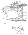
- the spring brake actuator has a main cylindrical body part denoted by reference 1. Within an open end 2 thereof there is a closure member or head part 3, retained by means of a retaining member in the form of a circular section wire circlip 4. Located inwardly of the retaining member 4 there is an annular seal 16 for preventing ingress of contaminants.
- a moveable wall in the form of a piston 6 which carries a tubular output member 7.
- Body 1, closure member 3, piston 6 and member 7 have a common axis 1a.
- the member 7 passes through a seal in the other end of the cylinder (not shown) to apply output force in the direction of arrow 15, to a brake lever when fluid pressure denoted by arrows 8 is reduced sufficiently for a heavy spring 9 to move the piston 6 to the right.
- the heavy spring 9 is shown in the drawing in its fully compressed condition and the piston 6 rests with its annular abutment surface 10 in engagement with a complimentary abutment surface 11 of the inner end of the closure member 3.
- the wire circlip 4 is trapped between first and second annular surfaces 12 and 13 of the cylinder 1 and the closure member 3 respectively. More particularly, respective generators 12a and 13a of the annular surfaces 12 and 13 are at 45° and 40° respectively of the cylinder.
- the reaction forces generated between the circlip 4 and the respective components 1 and 3 as shown in Fig. 2 are such as always to tend to drive the annular circlip 4 radially into its locking position in a retaining groove 14 in the inner surface at one end of the cylinder. The assembly is thereby rendered very secure.
Applications Claiming Priority (2)
| Application Number | Priority Date | Filing Date | Title |
|---|---|---|---|
| GB888807290A GB8807290D0 (en) | 1988-03-26 | 1988-03-26 | Retention means for components of pressure retaining vessels |
| GB8807290 | 1988-03-26 |
Publications (1)
| Publication Number | Publication Date |
|---|---|
| EP0336600A1 true EP0336600A1 (de) | 1989-10-11 |
Family
ID=10634203
Family Applications (1)
| Application Number | Title | Priority Date | Filing Date |
|---|---|---|---|
| EP89302771A Withdrawn EP0336600A1 (de) | 1988-03-26 | 1989-03-21 | Sicherungsmittel für Federspeicherdeckel |
Country Status (2)
| Country | Link |
|---|---|
| EP (1) | EP0336600A1 (de) |
| GB (2) | GB8807290D0 (de) |
Cited By (4)
| Publication number | Priority date | Publication date | Assignee | Title |
|---|---|---|---|---|
| WO1999045287A1 (fr) * | 1998-03-05 | 1999-09-10 | Gkn Automotive Ag | Organe de transmission mecanique et son application a un joint mecanique homocinetique |
| DE102007030982A1 (de) * | 2007-07-04 | 2009-01-08 | Volkswagen Ag | Anordnung zur axialen Sicherung und/oder zum axialen Toleranzausgleich eines Maschinenelementes, insbesondere eines Lagers, auf oder an einer Welle |
| US7597499B2 (en) | 2005-12-06 | 2009-10-06 | Rolls-Royce Plc | Retention arrangement |
| CN111795090A (zh) * | 2020-06-24 | 2020-10-20 | 桐乡市博达金属压铸有限公司 | 活塞式制动气室驻车腔弹簧定位系统 |
Citations (4)
| Publication number | Priority date | Publication date | Assignee | Title |
|---|---|---|---|---|
| US3218939A (en) * | 1962-04-26 | 1965-11-23 | Wagner Electric Corp | Friction device operating mechanism |
| US3240129A (en) * | 1964-05-28 | 1966-03-15 | Wagner Electric Corp | Disabling means for a friction device operating mechanism |
| FR2179295A5 (de) * | 1972-04-05 | 1973-11-16 | Saint Urbain Atel Metal | |
| US4351450A (en) * | 1981-06-08 | 1982-09-28 | General Motors Corporation | Groove structure for a retaining ring |
Family Cites Families (3)
| Publication number | Priority date | Publication date | Assignee | Title |
|---|---|---|---|---|
| GB1137191A (en) * | 1967-01-16 | 1968-12-18 | Steel Construction & Eng Co | Improvements in or relating to hydraulic cylinders |
| DE3230457C2 (de) * | 1982-08-16 | 1984-09-20 | Skw Trostberg Ag, 8223 Trostberg | Abdichtung für einen Hochdruck-Behälter mit Innenverschluß |
| GB8620088D0 (en) * | 1986-08-18 | 1986-10-01 | Wilson L P S | Securing of end caps in cylinders |
-
1988
- 1988-03-26 GB GB888807290A patent/GB8807290D0/en active Pending
-
1989
- 1989-03-21 EP EP89302771A patent/EP0336600A1/de not_active Withdrawn
- 1989-03-22 GB GB8906644A patent/GB2218466A/en not_active Withdrawn
Patent Citations (4)
| Publication number | Priority date | Publication date | Assignee | Title |
|---|---|---|---|---|
| US3218939A (en) * | 1962-04-26 | 1965-11-23 | Wagner Electric Corp | Friction device operating mechanism |
| US3240129A (en) * | 1964-05-28 | 1966-03-15 | Wagner Electric Corp | Disabling means for a friction device operating mechanism |
| FR2179295A5 (de) * | 1972-04-05 | 1973-11-16 | Saint Urbain Atel Metal | |
| US4351450A (en) * | 1981-06-08 | 1982-09-28 | General Motors Corporation | Groove structure for a retaining ring |
Cited By (6)
| Publication number | Priority date | Publication date | Assignee | Title |
|---|---|---|---|---|
| WO1999045287A1 (fr) * | 1998-03-05 | 1999-09-10 | Gkn Automotive Ag | Organe de transmission mecanique et son application a un joint mecanique homocinetique |
| FR2775741A1 (fr) * | 1998-03-05 | 1999-09-10 | Gkn Glaenzer Spicer | Organe de transmission mecanique et son application a un joint mecanique homocinetique |
| US6375576B1 (en) | 1998-03-05 | 2002-04-23 | Gkn Automotive Ag | Mechanical transmission member and its application to a mechanical constant velocity joint |
| US7597499B2 (en) | 2005-12-06 | 2009-10-06 | Rolls-Royce Plc | Retention arrangement |
| DE102007030982A1 (de) * | 2007-07-04 | 2009-01-08 | Volkswagen Ag | Anordnung zur axialen Sicherung und/oder zum axialen Toleranzausgleich eines Maschinenelementes, insbesondere eines Lagers, auf oder an einer Welle |
| CN111795090A (zh) * | 2020-06-24 | 2020-10-20 | 桐乡市博达金属压铸有限公司 | 活塞式制动气室驻车腔弹簧定位系统 |
Also Published As
| Publication number | Publication date |
|---|---|
| GB8807290D0 (en) | 1988-04-27 |
| GB2218466A (en) | 1989-11-15 |
| GB8906644D0 (en) | 1989-05-04 |
Similar Documents
| Publication | Publication Date | Title |
|---|---|---|
| JP2778963B2 (ja) | タンパー防止ブレーキ・アクチュエータ | |
| EP0400846B1 (de) | Ventil für Flüssigkeiten | |
| EP0316127B1 (de) | System mit Doppelsitz- und Entlüftungsventil | |
| US4649804A (en) | Mechanical release arrangement for a fluid-pressure-operated braking cylinder | |
| US5433138A (en) | Tamper-resistant brake actuator | |
| US5205205A (en) | Tamper resistant brake actuator | |
| EP0336600A1 (de) | Sicherungsmittel für Federspeicherdeckel | |
| MXPA98001220A (es) | Herramienta de liberacion de accionador de freno de muelle | |
| US5992297A (en) | Easy fit diaphragm | |
| EP1407172B1 (de) | Radial abgedichtete druckluftbremskammer | |
| US5676036A (en) | Small envelope tamper-resistant spring brake actuator | |
| US5715740A (en) | Combined piston rod alignment and sealing assembly for fluid actuator cylinders | |
| US5588348A (en) | Brake actuator with centering dome in service chamber | |
| AU2002307228A1 (en) | Radial sealed air brake chamber | |
| CA2010473A1 (en) | Apparatus for inserting valve seats in valve bodies | |
| US4981070A (en) | Multi-part piston for servomotor | |
| US5445257A (en) | Declutching device having a hydraulic actuator for snap-fitting on-to a pull-off type clutch | |
| US6217029B1 (en) | Seal arrangement for a piston rod | |
| JPH02171379A (ja) | 自動車用の真空ブレーキブースタ | |
| EP0074734B1 (de) | Betätigung für Bremsen od. dergl. | |
| US4502571A (en) | Rod lock mechanism | |
| EP1369328B1 (de) | Betätigungsvorrichtung für ein Bremsgerät | |
| EP0377928A1 (de) | Elastomerdichtung | |
| JPS6018442A (ja) | バルブ装置 | |
| US5036752A (en) | Hydraulic actuator having fail-safe feature with energy absorbing sleeve |
Legal Events
| Date | Code | Title | Description |
|---|---|---|---|
| PUAI | Public reference made under article 153(3) epc to a published international application that has entered the european phase |
Free format text: ORIGINAL CODE: 0009012 |
|
| AK | Designated contracting states |
Kind code of ref document: A1 Designated state(s): BE DE ES FR IT NL SE |
|
| STAA | Information on the status of an ep patent application or granted ep patent |
Free format text: STATUS: THE APPLICATION IS DEEMED TO BE WITHDRAWN |
|
| 18D | Application deemed to be withdrawn |
Effective date: 19900412 |