EP0335787B1 - A row floor-locking device for a telescoping seating system - Google Patents
A row floor-locking device for a telescoping seating system Download PDFInfo
- Publication number
- EP0335787B1 EP0335787B1 EP19890400845 EP89400845A EP0335787B1 EP 0335787 B1 EP0335787 B1 EP 0335787B1 EP 19890400845 EP19890400845 EP 19890400845 EP 89400845 A EP89400845 A EP 89400845A EP 0335787 B1 EP0335787 B1 EP 0335787B1
- Authority
- EP
- European Patent Office
- Prior art keywords
- row
- row floor
- floor
- pair
- locking device
- Prior art date
- Legal status (The legal status is an assumption and is not a legal conclusion. Google has not performed a legal analysis and makes no representation as to the accuracy of the status listed.)
- Expired
Links
- 230000006835 compression Effects 0.000 description 5
- 238000007906 compression Methods 0.000 description 5
- 238000010276 construction Methods 0.000 description 3
- 238000012423 maintenance Methods 0.000 description 1
- 238000009877 rendering Methods 0.000 description 1
- 238000004804 winding Methods 0.000 description 1
Images


Classifications
-
- E—FIXED CONSTRUCTIONS
- E04—BUILDING
- E04H—BUILDINGS OR LIKE STRUCTURES FOR PARTICULAR PURPOSES; SWIMMING OR SPLASH BATHS OR POOLS; MASTS; FENCING; TENTS OR CANOPIES, IN GENERAL
- E04H3/00—Buildings or groups of buildings for public or similar purposes; Institutions, e.g. infirmaries or prisons
- E04H3/10—Buildings or groups of buildings for public or similar purposes; Institutions, e.g. infirmaries or prisons for meetings, entertainments, or sports
- E04H3/12—Tribunes, grandstands or terraces for spectators
- E04H3/123—Telescopic grandstands
Definitions
- This invention relates to a row floor-locking device for a telescoping seating system having a plurality of row floors adapted to be extended or retracted like a nest of boxes.
- a telescoping seating system having a plurality of row floors adapted to be retracted and received below the next higher row floor when not in use like a nest of boxes, and extended forward and disposed in a stepped relation when in use, the seatings on each of the row floors being simultaneously stood up from their collapsed states to complete the seatings.
- Each of row floors is received below a highest (or rearmost) row floor “b” by winding a wire “c” whose forward end is fixed to a lowest (or foremost) row floor “b” provided with collapsible seating “a”, while whose rear end is wound around a drum “d”.
- a wire “e” is wound up.
- the forward end of the wire “e” is fixed to the lowest row floor “b” and the rear end of the wire “e” is wound around the drum “b” with the intermediate portion of the wire “e” being passed through between pairs of fixed pulleys "f” and "g” each provided at the rear portion of a row floor and at the forward portion of the bottom surface of the next higher row floor respectively.
- these row floors are extended in a stepped relation as shown in a dotted line in Fig. 8.
- Each of the row floors “b” is made movable on a floor “i” through wheels “h” on which each of the row floors "b” is supported.
- the third row floor "b" for example as a foremost seating row as shown in a solid line in Fig.8 depending on the kind of sports game or gathering to be held in a multi-purpose hall.
- a row floor-locking device so as to prevent the lowest row floor "b” and the next higher (or 2nd) row floor “b” from extending forward.
- the first object of this invention is to provide a row floor-locking device which is simple in structure and is capable of locking the row floors by making use of the rotating shaft of sprockets mounted in a row floor-linearly moving device of a telescoping seating system.
- a row floor-locking device for a telescoping seating system having a plurality of row floors capable of being extended forward and disposed in a stepped relation when in use, as well as of being retracted and received below the next higher row floor when not in use, and being provided whith a row floor-linearly moving device comprising a pair of driven sprockets each attached to left and right edge portions of the back side wall of the next lower row, and a pair of chains each forward end of which is fixed to left and right portions of the bottom surface of a row floor which is one step higher than said next lower row, each intermediate portion of which is wound around each of said driven sprockets, and each rear end of which is fixed to left and right portions of said bottom surface of the row floor thereby disposing said pair of chains generally in parallel with each other below said row floor; characterized in that said row floor-locking device comprises a gear wheel mounted in coaxial with the axes of said pair of sprocket
- the rack is forced by means of the driving means to engage with the gear wheel mounted in coaxial with the axes of the driven sprocket thereby to stop the gear wheel from rotating. Therefore, the row floor-linearly moving device comprising the driven sprocket and a length of chain engaged therewith is also stopped moving.
- each driven sprocket moves forward pulling the chain therearound.
- the pair of the driven sprockets disposed at the right and left sides of the row floor are simultaneously and linearly moved at the same speed one another while being guided by the next higher row floor.
- the numeral 1 generally designates a telescoping seating system comprising a plurality of row floors. As show in Fig. 1, the more forward a row floor is disposed, the width and height of a row floor are made smaller.
- the numeral 2 indicated the foremost row floor and the numerals 3 and 4 indicated respectively second and third row floors disposed rearward of the foremost row floor 2.
- row floors 2, 3 and 4 are received below a highest row floor (not shown) like a nest of boxes when not in use. However, when in use, they are capable of being extended forward to be set like a steps while being linked each other. These movements of the row floors are effected by means of a driving means (not shown).
- the mechanism for moving these row floors is the same as explained with reference to Fig. 8 so that explanations on this mechanism will be omitted.
- the foremost row floor 2 takes the form of a box having an open bottom, i.e. comprises a supporting top plate 2a, attached with a front wall plate 2b, a back wall plate 2c and a pair of side wall plates 2d, each extending downward from the sides of the top plate 2a.
- next higher row floor 3 is provided on the sides thereof with a front wall plate 3b, a back wall plate 3c and a pair of side wall plates 3e each extending downward
- row floor 4 is provided on the sides thereof with a front wall plate 4b, a back wall plate 4c and a pair of side wall plates 4d, each extending downward.
- each mounting plate 5 On the upper portion of each mounting plate 5 is attached a pair of shafts 6 and 7 extending inward and perpendicular to the mounting plate 5.
- a pair of guiding sprockets 8 and 9 are rotatably mounted on the shafts 6 and 7 respectively.
- a bearing is provided on each mounting plate 5 below an intermediate position between the guiding sprockets 8 and 9. Between the bearings mounted respectively on the pair of the mounting plates 5 is rotatably supported a horizontal connecting shaft 10.
- a driven sprocket 11 is attached to each left and right side portion of the connecting shaft 10 so as to be rotated together with the connecting shaft 10.
- the numeral 12 indicates a left side roller chain extending in a direction parallel to the moving direction of the row floors.
- the forward end portion 12a of the roller chain is fastened to a left lower portion of the back surface of the front wall plate 3b of the row floor 3.
- the intermediate portion 12b of the roller chain is wound around in the order of the guiding sprocket 8, the driven sprocket 11 and the guiding sprocket 9 so that the roller chain is formed into a shape of a reversed letter.
- the rear end portion of the roller chain is fastened to the front surface of the back wall plate 3c of the row floor 3.
- the right side roller chain is disposed in symmetry with the left side roller chain, so that the forward end portion 13a, the intermediate portion 13b and the rear end portion of the right side roller chain are mounted respectively in the same manner as those of the left side roller chain.
- a set of the guiding sprockets 8 and 9, and the driven sprocket 11 as mentioned above are also mounted on each of the mounting plates 15 attached to the next higher row floor 3, and a pair of roller chains 12 and 13 are stretched in parallel with each other at both sides of the row floor 13 and wound around these sprockets 8, 9 and 11.
- the numeral 5 is a gear wheel for braking, which is fitted on approximately the middle portion of the connecting shaft 10, constituting itself as one element of the row floor-locking means 14. This gear wheel 15 is fastened to the connecting shaft 10 by means of key 16 and a pair of setscrews 17.
- the numeral 18 indicates an L-shaped mounting plate attached to the back wall plate 2c of the row floor 2. On this mounting plate 18 is mounted a U-shaped frame 19 the back side of which opens.
- the frame 19 is mounted to the mounting plate 18 by means of nuts 21b and bolts 21a, each of which is pierced through the left and right side wall plates 19a of the frame 19 and each of a pair of spacing members 20.
- the numeral 24 indicates a rack constituting the other element of the locking means 14.
- the lower end portion of the rack 24 is rotatably mounted on the frame 19 via a shaft 25 pierced through the lower end portion of the rack 24.
- the intermediate portion of the rack 24 is connected to the near end portion of the reciprocating rod 22b of the solenoid 22.
- a compression coil spring 27 forward end portion of which is idly fitted and inserted over a bolt 26 projecting backward from the inner surface of the bottom plate 19b.
- the gear tooth 24a of the rack 14 is always energized toward the front end portion of the gear wheel 15 by the elastic force of this compression coil spring 27.
- the gear wheel 15 is stopped from rotating by means of the rack 24 due to the energized force of the compression coil spring 27, and therefore the shaft 10 is also prevented from rotating. Accordingly, even if the row floor 2 is pushed forward by means of a moving means, it can not move forward beyond the row floor 3, i.e. the row floor 2 is forced to move forward or backward together with the row floor 3.
- the shaft 10 is set free to rotate, and can be rotated by moving means (not shown) to allow the row floor 2 to be extended forward.
- a pair of driven sprockets 11 mounted at the left and right sides of the row floor 2 and connected to the shaft 10 is simultaneously rotated, so that the row floor 2 can be linearly moved without swaying left and right while being guided by the row floor 3.
- Fig. 5 and 6 show another example of this invention.
- the numeral 28 indicates the foremost row floor.
- a pair of double sprockets 29a, 29b, 30a and 30b each disposed at the left and right sides of the back surface and composed of an upper driven sprocket and a lower driven sprocket.
- roller chain 32 On the left side of the back surface of the front wall plate of a row floor 31 next to the row floor 28 is mounted a roller chain 32 whose forward end portion 32a extends in the direction parallel with the moving direction of the row floors.
- the intermediate portion 32b of the roller chain 32 is wound around both the upper left sprocket 29a and the upper right sprocket 30a.
- the rear end portion of the roller chain 32 is fixed to the right side of the back surface of the row floor 31.
- roller chain 33 is disposed at the position slightly lower than the roller chain 32 and in symmetry with the roller chain 32.
- the forward end portion 33a is fastened and extended in the direction parallel to the moving direction of the row floors.
- the intermediate portion 33b of the roller chain 33 is wound around both the lower left sprocket 29b and the lower right sprocket 30b.
- the rear end portion of the roller chain 33 is fixed to the left side of the back surface of the row floor 31.
- the pair of roller chains 32 and 33 is wound around the double sprockets 29a, 29b, 30a and 30b, intercrossing each other.
- a pair of gear wheels for braking 34 which is adapted to be rotated en bloc with these double sprockets.
- the numeral 35 indicates locking means having almost the same structure as that of the first example. This locking means will be explained briefly.
- the rack 37 is energized by the compression coil spring 36 so as to always engage with the gear wheel 34, but can be disengaged from the gear wheel 34 as it is actuated by the solenoid 38.
- the row floor 28 can be extended out of the row floor 31.
- the double sprockets 29a, 29b 30a, 30b are stopped from rotating, and therefore, the row floor 28 is extended forward or retracted backward together with the row floor 31.
- Fig. 7 shows another modified example of locking means 14 shown in Fig. 3.
- the same parts as shown in aforementioned example will be indicated in the same numerals.
- the rack 39 is always energized by a torsion spring 40 idly fitted on the rod 5 so as to force the gear tooth 39a to engage with the gear wheel 15.
- a torsion spring 40 idly fitted on the rod 5 so as to force the gear tooth 39a to engage with the gear wheel 15.
- a forwardly facing step 39b On the front upper edge portion of the rack 39 is formed a forwardly facing step 39b.
- the numeral 41 is a locking member, the forward end portion of which is rotatably supported on a shaft 42 extending in a direction perpendicular to the moving direction of the row floor.
- the locking member 41 has a step-like engaging portion 41a at the lower surface of the rear end portion thereof. This engaging portion 41a is adapted to be detachably engaged with the step 39b of the rack 39.
- the locking member 41 is always energized by means of a torsion spring 43 idly fitted on the shaft 42 so as to rotate counter-clockwise.
- the intermediate portion between the forward end and the rear end of the locking member 41 is rotatably connected with a reciprocating rod 44a of the solenoid 44 so as to move the locking member 41 up and down.
- solenoid 44 is actuated so that the engaging portion 41a of the locking member 41 is usually raised up and the rack 39 is set free to rotate.
- the actuation of the solenoid 44 is released and the locking member 41 is lowered to render the engaging portion 41a to engage with the step 39b thereby locking the rack 39.
- the stop of the rotation of the driven sprocket shaft is effected by causing the gear wheel for braking mounted on the sprocket shaft to engage with the rack.
- it is also possible to stop the rotation of the driven sprocket shaft by mounting a disk on the shaft, positioning a locking member near the disk, and causing as desired the locking member to frictionally contact with the disk.
- the locking or releasing of the row floors is effected by making use of a row floor-linearly moving device comprising a combination of driven sprockets and chains mounted between row floors for linearly moving the row floors.
- a gear wheel is mounted on the shaft of driven sprocket, and the gear wheel is caused to engage with or disengage from a rack thereby effecting the locking or releasing of the row floor. Therefore, according to this invention, the locking device for a telescoping seating system can be made very simple in structure.
- the locking device of this invention can be utilized for locking the row floors when they are not in use, as well as for preventing the row floor from jolting when in use.
Landscapes
- Engineering & Computer Science (AREA)
- Architecture (AREA)
- Civil Engineering (AREA)
- Structural Engineering (AREA)
- Floor Finish (AREA)
- Chairs For Special Purposes, Such As Reclining Chairs (AREA)
Description
- This invention relates to a row floor-locking device for a telescoping seating system having a plurality of row floors adapted to be extended or retracted like a nest of boxes.
- In a multi-purpose hall or the like, it is known to employ a telescoping seating system having a plurality of row floors adapted to be retracted and received below the next higher row floor when not in use like a nest of boxes, and extended forward and disposed in a stepped relation when in use, the seatings on each of the row floors being simultaneously stood up from their collapsed states to complete the seatings.
- An example of such a telescoping seating system for extending or retracting steps-like floors is taught for example in Japanese Patent Application No 61-121000 (1986).
- The construction of the telescoping seating system according the Japanese Patent Application will be explained below with reference to Fig. 8.
- Each of row floors is received below a highest (or rearmost) row floor "b" by winding a wire "c" whose forward end is fixed to a lowest (or foremost) row floor "b" provided with collapsible seating "a", while whose rear end is wound around a drum "d". When it is required to extend forward the row floors, a wire "e" is wound up. The forward end of the wire "e" is fixed to the lowest row floor "b" and the rear end of the wire "e" is wound around the drum "b" with the intermediate portion of the wire "e" being passed through between pairs of fixed pulleys "f" and "g" each provided at the rear portion of a row floor and at the forward portion of the bottom surface of the next higher row floor respectively. Usually, these row floors are extended in a stepped relation as shown in a dotted line in Fig. 8.
- Each of the row floors "b" is made movable on a floor "i" through wheels "h" on which each of the row floors "b" is supported.
- With this telescoping seating system, it is possible to use the third row floor "b" for example as a foremost seating row as shown in a solid line in Fig.8 depending on the kind of sports game or gathering to be held in a multi-purpose hall. In such a case, it is required to employ a row floor-locking device so as to prevent the lowest row floor "b" and the next higher (or 2nd) row floor "b" from extending forward.
- An example of such a row floor-locking device is disclosed in Japanese Patent Laid-Open Publication No 62-23950. However, according to the row floor-locking device of this prior art, it is required to install a pair of linking mechanism on both sides of the pushing plate, thereby requiring a number of parts and rendering the whole device complicated in structure and troublesome in assembling and maintenance.
- The first object of this invention is to provide a row floor-locking device which is simple in structure and is capable of locking the row floors by making use of the rotating shaft of sprockets mounted in a row floor-linearly moving device of a telescoping seating system.
- According to a first feature of this invention, there is provided a row floor-locking device for a telescoping seating system having a plurality of row floors capable of being extended forward and disposed in a stepped relation when in use, as well as of being retracted and received below the next higher row floor when not in use, and being provided whith a row floor-linearly moving device comprising a pair of driven sprockets each attached to left and right edge portions of the back side wall of the next lower row, and a pair of chains each forward end of which is fixed to left and right portions of the bottom surface of a row floor which is one step higher than said next lower row, each intermediate portion of which is wound around each of said driven sprockets, and each rear end of which is fixed to left and right portions of said bottom surface of the row floor thereby disposing said pair of chains generally in parallel with each other below said row floor;
characterized in that said row floor-locking device comprises a gear wheel mounted in coaxial with the axes of said pair of sprockets, a rack adapted to detachably engage with said gear wheel thereby to stop said gear wheel from rotating, and driving means for engaging said rack with or disengaging said rack from said gear wheel. - When the row floor-locking device is actuated, the rack is forced by means of the driving means to engage with the gear wheel mounted in coaxial with the axes of the driven sprocket thereby to stop the gear wheel from rotating. Therefore, the row floor-linearly moving device comprising the driven sprocket and a length of chain engaged therewith is also stopped moving.
- Therefore, the row floors locked by the row floor-locking device move back and forth en bloc.
- When the locking motion of the row floor-locking device is set free, the rack is disengaged from the gear wheel mounted on the shaft of the driven sprocket, and the row floor-linearly moving device is set free to move.
- When the row floors are being extended, each driven sprocket moves forward pulling the chain therearound.
- In this case, the pair of the driven sprockets disposed at the right and left sides of the row floor are simultaneously and linearly moved at the same speed one another while being guided by the next higher row floor.
- Other features and advantages of this invention will be made clear by the following explanation based on the accompanying drawings, wherein:
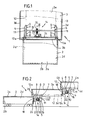
- Fig. 1 is a partially cut plan view showing one example of a row floor-locking device according to this invention;
- Fig. 2 is vertical sectional view of the row floor-locking device shown in Fig. 1;
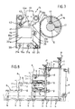
- Fig. 3 is partially cut sectional view taken along the line III-III in Fig. 1;
- Fig. 4 is a front view of the Fig. 3;
- Fig. 5 is partially cut plan view showing another exemple of a row floor-locking device according this invention;
- Fig. 6 is an enlarged vertical sectional view of the Fig. 5;
- Fig. 7 is a vertical sectional view of a row floor-locking device according to another example of this invention;
- Fig. 8 is a schematic side view showing an example of the moving means of the conventional telescoping seating system.
- One example of a row floor-locking device according to this invention will be explained below with reference to Figs. 1 to 4. First of all, the construction of a row floor-linearly moving device will be explained.
- The
numeral 1 generally designates a telescoping seating system comprising a plurality of row floors. As show in Fig. 1, the more forward a row floor is disposed, the width and height of a row floor are made smaller. Thenumeral 2 indicated the foremost row floor and thenumerals foremost row floor 2. - These
row floors - The mechanism for moving these row floors is the same as explained with reference to Fig. 8 so that explanations on this mechanism will be omitted. The
foremost row floor 2 takes the form of a box having an open bottom, i.e. comprises a supportingtop plate 2a, attached with afront wall plate 2b, aback wall plate 2c and a pair ofside wall plates 2d, each extending downward from the sides of thetop plate 2a. - Likewise, the next
higher row floor 3 is provided on the sides thereof with afront wall plate 3b, aback wall plate 3c and a pair of side wall plates 3e each extending downward, and therow floor 4 is provided on the sides thereof with afront wall plate 4b, a back wall plate 4c and a pair ofside wall plates 4d, each extending downward. - On the upper portion of each side of the
back wall plates row floors mounting plate 5 perpendicularly projecting rearward. - On the upper portion of each
mounting plate 5 is attached a pair ofshafts mounting plate 5. A pair of guidingsprockets 8 and 9 are rotatably mounted on theshafts mounting plate 5 below an intermediate position between the guidingsprockets 8 and 9. Between the bearings mounted respectively on the pair of themounting plates 5 is rotatably supported a horizontal connectingshaft 10. A drivensprocket 11 is attached to each left and right side portion of the connectingshaft 10 so as to be rotated together with the connectingshaft 10. - The
numeral 12 indicates a left side roller chain extending in a direction parallel to the moving direction of the row floors. Theforward end portion 12a of the roller chain is fastened to a left lower portion of the back surface of thefront wall plate 3b of therow floor 3. Theintermediate portion 12b of the roller chain is wound around in the order of the guidingsprocket 8, the drivensprocket 11 and the guiding sprocket 9 so that the roller chain is formed into a shape of a reversed letter. The rear end portion of the roller chain is fastened to the front surface of theback wall plate 3c of therow floor 3. - The right side roller chain is disposed in symmetry with the left side roller chain, so that the
forward end portion 13a, the intermediate portion 13b and the rear end portion of the right side roller chain are mounted respectively in the same manner as those of the left side roller chain. - A set of the guiding
sprockets 8 and 9, and the drivensprocket 11 as mentioned above are also mounted on each of themounting plates 15 attached to the nexthigher row floor 3, and a pair ofroller chains row floor 13 and wound around thesesprockets - Next, a row floor-locking means 14 which is detachably engaged with the
shaft 10 of the drivensprocket 11 of the row floor-linearly moving device will be explained. - The
numeral 5 is a gear wheel for braking, which is fitted on approximately the middle portion of the connectingshaft 10, constituting itself as one element of the row floor-locking means 14. Thisgear wheel 15 is fastened to the connectingshaft 10 by means ofkey 16 and a pair ofsetscrews 17. - The
numeral 18 indicates an L-shaped mounting plate attached to theback wall plate 2c of therow floor 2. On thismounting plate 18 is mounted aU-shaped frame 19 the back side of which opens. - Namely, as shown in Fig. 4, the
frame 19 is mounted to themounting plate 18 by means ofnuts 21b andbolts 21a, each of which is pierced through the left and rightside wall plates 19a of theframe 19 and each of a pair ofspacing members 20. - At the middle portion of the
frame 19 is fastened thecoil portion 22a of asolenoid 22 by means of asetscrew 23. - The
numeral 24 indicates a rack constituting the other element of the locking means 14. The lower end portion of therack 24 is rotatably mounted on theframe 19 via ashaft 25 pierced through the lower end portion of therack 24. The intermediate portion of therack 24 is connected to the near end portion of the reciprocatingrod 22b of thesolenoid 22. - As shown in Fig.3, between the upper end portion of the back surface of the
rack 24 and thebottom plate 19b of theframe 19 is disposed acompression coil spring 27, forward end portion of which is idly fitted and inserted over abolt 26 projecting backward from the inner surface of thebottom plate 19b. Thegear tooth 24a of therack 14 is always energized toward the front end portion of thegear wheel 15 by the elastic force of thiscompression coil spring 27. - Accordingly, when the locking means 14 is actuated, i.e. when the
solenoid 22 is not activated, thegear wheel 15 is stopped from rotating by means of therack 24 due to the energized force of thecompression coil spring 27, and therefore theshaft 10 is also prevented from rotating. Accordingly, even if therow floor 2 is pushed forward by means of a moving means, it can not move forward beyond therow floor 3, i.e. therow floor 2 is forced to move forward or backward together with therow floor 3. - When the locking means 14 is set free, i.e. when the
solenoid 22 is turned on, therack 24 is pulled back by thereciprocating rod 22b in resistance to the elastic force of thecompression coil spring 27, thereby releasing the engagement between thegear tooth 24a and thegear wheel 15. - Accordingly, the
shaft 10 is set free to rotate, and can be rotated by moving means (not shown) to allow therow floor 2 to be extended forward. - In this case, a pair of driven
sprockets 11 mounted at the left and right sides of therow floor 2 and connected to theshaft 10 is simultaneously rotated, so that therow floor 2 can be linearly moved without swaying left and right while being guided by therow floor 3. - Fig. 5 and 6 show another example of this invention.
- The numeral 28 indicates the foremost row floor. On the upper portion of the back surface of the back wall plate 28a of the
foremost row floor 28 is mounted a pair ofdouble sprockets - On the left side of the back surface of the front wall plate of a
row floor 31 next to therow floor 28 is mounted aroller chain 32 whoseforward end portion 32a extends in the direction parallel with the moving direction of the row floors. Theintermediate portion 32b of theroller chain 32 is wound around both the upper left sprocket 29a and the upperright sprocket 30a. The rear end portion of theroller chain 32 is fixed to the right side of the back surface of therow floor 31. - Another
roller chain 33 is disposed at the position slightly lower than theroller chain 32 and in symmetry with theroller chain 32. Theforward end portion 33a is fastened and extended in the direction parallel to the moving direction of the row floors. Theintermediate portion 33b of theroller chain 33 is wound around both the lowerleft sprocket 29b and the lowerright sprocket 30b. The rear end portion of theroller chain 33 is fixed to the left side of the back surface of therow floor 31. - In this manner, the pair of
roller chains double sprockets row floor 2 to move linearly while being guided by therow floor 3. - As shown in Fig. 6, between the
double sprockets 29a and 29b, and thedouble sprockets - The numeral 35 indicates locking means having almost the same structure as that of the first example. This locking means will be explained briefly.
- The
rack 37 is energized by thecompression coil spring 36 so as to always engage with thegear wheel 34, but can be disengaged from thegear wheel 34 as it is actuated by thesolenoid 38. - Accordingly, when the locking means 35 is not actuated, the
row floor 28 can be extended out of therow floor 31. On the other hand, when the locking means 35 is actuated, thedouble sprockets 29a,29b row floor 28 is extended forward or retracted backward together with therow floor 31. - Fig. 7 shows another modified example of locking means 14 shown in Fig. 3. The same parts as shown in aforementioned example will be indicated in the same numerals.
- The
rack 39 is always energized by atorsion spring 40 idly fitted on therod 5 so as to force thegear tooth 39a to engage with thegear wheel 15. On the front upper edge portion of therack 39 is formed a forwardly facing step 39b. - The numeral 41 is a locking member, the forward end portion of which is rotatably supported on a
shaft 42 extending in a direction perpendicular to the moving direction of the row floor. The lockingmember 41 has a step-likeengaging portion 41a at the lower surface of the rear end portion thereof. This engagingportion 41a is adapted to be detachably engaged with the step 39b of therack 39. - The locking
member 41 is always energized by means of atorsion spring 43 idly fitted on theshaft 42 so as to rotate counter-clockwise. The intermediate portion between the forward end and the rear end of the lockingmember 41 is rotatably connected with areciprocating rod 44a of thesolenoid 44 so as to move the lockingmember 41 up and down. - Accordingly, usually solenoid 44 is actuated so that the engaging
portion 41a of the lockingmember 41 is usually raised up and therack 39 is set free to rotate. However, once therack 39 is engaged with thegear wheel 15, the actuation of thesolenoid 44 is released and the lockingmember 41 is lowered to render the engagingportion 41a to engage with the step 39b thereby locking therack 39. - In the above examples, the stop of the rotation of the driven sprocket shaft is effected by causing the gear wheel for braking mounted on the sprocket shaft to engage with the rack. However, it is also possible to stop the rotation of the driven sprocket shaft by mounting a disk on the shaft, positioning a locking member near the disk, and causing as desired the locking member to frictionally contact with the disk.
- According to the row floor-locking device for a telescoping seating system, the locking or releasing of the row floors is effected by making use of a row floor-linearly moving device comprising a combination of driven sprockets and chains mounted between row floors for linearly moving the row floors. To be more specific, a gear wheel is mounted on the shaft of driven sprocket, and the gear wheel is caused to engage with or disengage from a rack thereby effecting the locking or releasing of the row floor. Therefore, according to this invention, the locking device for a telescoping seating system can be made very simple in structure.
- Further, the locking device of this invention can be utilized for locking the row floors when they are not in use, as well as for preventing the row floor from jolting when in use.
Claims (3)
Priority Applications (1)
| Application Number | Priority Date | Filing Date | Title |
|---|---|---|---|
| EP91400412A EP0430931B1 (en) | 1988-03-30 | 1989-03-24 | A row floor-locking device for a telescoping seating system |
Applications Claiming Priority (4)
| Application Number | Priority Date | Filing Date | Title |
|---|---|---|---|
| JP4106388U JPH0748895Y2 (en) | 1988-03-30 | 1988-03-30 | Stepped mooring device in the moving bleachers |
| JP41063/88 | 1988-03-30 | ||
| JP41830/88 | 1988-03-31 | ||
| JP4183088U JPH0427966Y2 (en) | 1988-03-31 | 1988-03-31 |
Related Child Applications (1)
| Application Number | Title | Priority Date | Filing Date |
|---|---|---|---|
| EP91400412.2 Division-Into | 1989-03-24 |
Publications (2)
| Publication Number | Publication Date |
|---|---|
| EP0335787A1 EP0335787A1 (en) | 1989-10-04 |
| EP0335787B1 true EP0335787B1 (en) | 1991-11-06 |
Family
ID=26380595
Family Applications (2)
| Application Number | Title | Priority Date | Filing Date |
|---|---|---|---|
| EP19890400845 Expired EP0335787B1 (en) | 1988-03-30 | 1989-03-24 | A row floor-locking device for a telescoping seating system |
| EP91400412A Expired - Lifetime EP0430931B1 (en) | 1988-03-30 | 1989-03-24 | A row floor-locking device for a telescoping seating system |
Family Applications After (1)
| Application Number | Title | Priority Date | Filing Date |
|---|---|---|---|
| EP91400412A Expired - Lifetime EP0430931B1 (en) | 1988-03-30 | 1989-03-24 | A row floor-locking device for a telescoping seating system |
Country Status (2)
| Country | Link |
|---|---|
| EP (2) | EP0335787B1 (en) |
| DE (2) | DE68925362T2 (en) |
Families Citing this family (3)
| Publication number | Priority date | Publication date | Assignee | Title |
|---|---|---|---|---|
| FR2701642B1 (en) * | 1993-02-17 | 1995-05-19 | Doublet Ets | Improvements to grandstands with telescopic elements. |
| FR2746433B1 (en) * | 1996-03-20 | 1998-06-19 | Husson Collectivites Sa | TELESCOPIC STAND WITH A ROW LOCKING DEVICE |
| CN117470473B (en) * | 2023-10-30 | 2025-02-21 | 盱眙国联建设工程质量检测有限公司 | Pipeline weld detection device |
Family Cites Families (3)
| Publication number | Priority date | Publication date | Assignee | Title |
|---|---|---|---|---|
| US3157916A (en) * | 1960-05-18 | 1964-11-24 | Safway Steel Products Inc | Locking mechanism for collapsible bleacher |
| US3667171A (en) * | 1971-01-08 | 1972-06-06 | American Seating Co | Row folding seating structure |
| NL7902899A (en) * | 1979-04-12 | 1980-10-14 | Nijha Nv | EXTENDABLE STAND. |
-
1989
- 1989-03-24 DE DE1989625362 patent/DE68925362T2/en not_active Expired - Fee Related
- 1989-03-24 EP EP19890400845 patent/EP0335787B1/en not_active Expired
- 1989-03-24 DE DE8989400845T patent/DE68900405D1/en not_active Expired - Lifetime
- 1989-03-24 EP EP91400412A patent/EP0430931B1/en not_active Expired - Lifetime
Also Published As
| Publication number | Publication date |
|---|---|
| DE68925362T2 (en) | 1996-06-20 |
| EP0430931A2 (en) | 1991-06-05 |
| EP0430931B1 (en) | 1996-01-03 |
| DE68925362D1 (en) | 1996-02-15 |
| EP0335787A1 (en) | 1989-10-04 |
| EP0430931A3 (en) | 1992-03-18 |
| DE68900405D1 (en) | 1991-12-12 |
Similar Documents
| Publication | Publication Date | Title |
|---|---|---|
| DE68909364T2 (en) | Seat positioning mechanism. | |
| DE3338016C2 (en) | Control lever assembly for self-propelled lawn mowers | |
| DE102017209330B4 (en) | Drive device for a vehicle seat, in particular a vehicle seat, and a vehicle seat | |
| DE69004516T2 (en) | Conveyors with self-drive carriers. | |
| DE102007034220A1 (en) | Movable headrest for improved visibility | |
| EP0335787A1 (en) | A row floor-locking device for a telescoping seating system | |
| EP0659636B1 (en) | Transmission with energy storing system for a bicycle | |
| DE2310554A1 (en) | RUBBER BELT DRIVE FOR PLAY VEHICLES | |
| US4037695A (en) | Interlock for a vehicle brake and clutch control | |
| DE3731847C2 (en) | ||
| US3361279A (en) | Bale collector | |
| DE69423644T2 (en) | SHOPPING CART WITH STEERING WHEEL WITH LOCKING DEVICE | |
| DE69519543T2 (en) | Stand for motorcycle | |
| DE3332475C2 (en) | ||
| DE3545298C2 (en) | ||
| JPH0748895Y2 (en) | Stepped mooring device in the moving bleachers | |
| US4445698A (en) | Roller skate with user powered drive mechanism | |
| EP0337592B1 (en) | Stepped floor moving apparatus for movable stand | |
| JPH06501413A (en) | Propulsion mechanism especially for wheelchairs | |
| EP0433731B1 (en) | Motor starting device | |
| DE102007029942B4 (en) | Seat height adjustment mechanism | |
| CN111915747A (en) | Automatic parking charging telescopic pile device for preventing ticket evasion with car | |
| JP3647310B2 (en) | Rice transplanter planting structure | |
| DE58444C (en) | Bicycle operated by the rider's torso moving up and down | |
| DE102005018556A1 (en) | Bicycle with combined crank-wheel drive |
Legal Events
| Date | Code | Title | Description |
|---|---|---|---|
| PUAI | Public reference made under article 153(3) epc to a published international application that has entered the european phase |
Free format text: ORIGINAL CODE: 0009012 |
|
| AK | Designated contracting states |
Kind code of ref document: A1 Designated state(s): DE FR GB NL |
|
| 17P | Request for examination filed |
Effective date: 19891024 |
|
| 17Q | First examination report despatched |
Effective date: 19901029 |
|
| GRAA | (expected) grant |
Free format text: ORIGINAL CODE: 0009210 |
|
| AK | Designated contracting states |
Kind code of ref document: B1 Designated state(s): DE FR GB NL |
|
| XX | Miscellaneous (additional remarks) |
Free format text: TEILANMELDUNG 91400412.2 EINGEREICHT AM 24/03/89. |
|
| REF | Corresponds to: |
Ref document number: 68900405 Country of ref document: DE Date of ref document: 19911212 |
|
| ET | Fr: translation filed | ||
| PLBE | No opposition filed within time limit |
Free format text: ORIGINAL CODE: 0009261 |
|
| STAA | Information on the status of an ep patent application or granted ep patent |
Free format text: STATUS: NO OPPOSITION FILED WITHIN TIME LIMIT |
|
| 26N | No opposition filed | ||
| PGFP | Annual fee paid to national office [announced via postgrant information from national office to epo] |
Ref country code: FR Payment date: 19980202 Year of fee payment: 10 |
|
| PGFP | Annual fee paid to national office [announced via postgrant information from national office to epo] |
Ref country code: GB Payment date: 19980317 Year of fee payment: 10 |
|
| PGFP | Annual fee paid to national office [announced via postgrant information from national office to epo] |
Ref country code: NL Payment date: 19980331 Year of fee payment: 10 |
|
| PGFP | Annual fee paid to national office [announced via postgrant information from national office to epo] |
Ref country code: DE Payment date: 19980527 Year of fee payment: 10 |
|
| PG25 | Lapsed in a contracting state [announced via postgrant information from national office to epo] |
Ref country code: GB Free format text: LAPSE BECAUSE OF NON-PAYMENT OF DUE FEES Effective date: 19990324 |
|
| PG25 | Lapsed in a contracting state [announced via postgrant information from national office to epo] |
Ref country code: NL Free format text: LAPSE BECAUSE OF NON-PAYMENT OF DUE FEES Effective date: 19991001 |
|
| GBPC | Gb: european patent ceased through non-payment of renewal fee |
Effective date: 19990324 |
|
| PG25 | Lapsed in a contracting state [announced via postgrant information from national office to epo] |
Ref country code: FR Free format text: LAPSE BECAUSE OF NON-PAYMENT OF DUE FEES Effective date: 19991130 |
|
| NLV4 | Nl: lapsed or anulled due to non-payment of the annual fee |
Effective date: 19991001 |
|
| REG | Reference to a national code |
Ref country code: FR Ref legal event code: ST |
|
| PG25 | Lapsed in a contracting state [announced via postgrant information from national office to epo] |
Ref country code: DE Free format text: LAPSE BECAUSE OF NON-PAYMENT OF DUE FEES Effective date: 20000101 |