EP0335126A2 - Jeweler's multi-axial work support and positioning device - Google Patents
Jeweler's multi-axial work support and positioning device Download PDFInfo
- Publication number
- EP0335126A2 EP0335126A2 EP89103670A EP89103670A EP0335126A2 EP 0335126 A2 EP0335126 A2 EP 0335126A2 EP 89103670 A EP89103670 A EP 89103670A EP 89103670 A EP89103670 A EP 89103670A EP 0335126 A2 EP0335126 A2 EP 0335126A2
- Authority
- EP
- European Patent Office
- Prior art keywords
- platen
- slide
- micro
- shellac
- combination
- Prior art date
- Legal status (The legal status is an assumption and is not a legal conclusion. Google has not performed a legal analysis and makes no representation as to the accuracy of the status listed.)
- Withdrawn
Links
Images


Classifications
-
- A—HUMAN NECESSITIES
- A44—HABERDASHERY; JEWELLERY
- A44C—PERSONAL ADORNMENTS, e.g. JEWELLERY; COINS
- A44C27/00—Making jewellery or other personal adornments
-
- B—PERFORMING OPERATIONS; TRANSPORTING
- B25—HAND TOOLS; PORTABLE POWER-DRIVEN TOOLS; MANIPULATORS
- B25H—WORKSHOP EQUIPMENT, e.g. FOR MARKING-OUT WORK; STORAGE MEANS FOR WORKSHOPS
- B25H1/00—Work benches; Portable stands or supports for positioning portable tools or work to be operated on thereby
- B25H1/02—Work benches; Portable stands or supports for positioning portable tools or work to be operated on thereby of table type
-
- B—PERFORMING OPERATIONS; TRANSPORTING
- B25—HAND TOOLS; PORTABLE POWER-DRIVEN TOOLS; MANIPULATORS
- B25H—WORKSHOP EQUIPMENT, e.g. FOR MARKING-OUT WORK; STORAGE MEANS FOR WORKSHOPS
- B25H1/00—Work benches; Portable stands or supports for positioning portable tools or work to be operated on thereby
- B25H1/10—Work benches; Portable stands or supports for positioning portable tools or work to be operated on thereby with provision for adjusting holders for tool or work
Definitions
- the present invention relates in general to a multi-axial work support and positioning device for use in the manufacture and repair of jewelry which greatly increases the efficiency of the jeweler in performing his work.
- the device represents a major advance in the equipment available to a skilled jeweler and thereby a corresponding increase in production and a reduction in costs.
- Emmert (709,399) is directed to a multi-jawed vise supported on a stationery base A and a heavy upstanding column C.
- the vise may be swiveled in a horizontal place through 360 degrees about the column C.
- the vise may also be swiveled bodily about horizontal axis d′. It may be adjusted further rotatably about a horizontal axis in bearing D.
- the Kapp patent (851,292) shows an adjustable bench pin 1, 29 mounted on a heavy work bench 9 by means of a clamp 2.
- Two swivel fittings 11, 16 and 32, 34, along with adjustable pin 26, permit the bench pin to be adjusted about a vertical axis and also about two different horizontal axes to accommodate the needs of the jeweler.
- the Rowland patent (1,446,811) shows a work holding clamp assembly consisting of a supporting bar or rod 3 mounted on a work bench or other support by means of brackets 1, 2.
- Spherical clamp connections 8, 13, 21, 27 support screw clamps 12 and 26 to hold relatively heavy parts for welding or other operations.
- the Merrell patent (4,295,640) shows a ring and bracelet mandrel arrangement adjustably supported upon an elongated rectangular base 14 and an upright holder 16.
- the patent to Reed et al. (4,595,186) is directed to a rotatable welding fixture for holding a pipe fitting against a welding table so that socket welds between the fitting and a length of pipe can be fabricated in one continuous operation.
- the unit comprises a small vertically adjustable work table fixed to a central depending spindle 16 which is rotatably and telescopically supported in an upstanding tubular column 13.
- a cube shaped clamping unit 30 is mounted on top of the table and provided with a series of different diameter dowels 36-39 to hold a pipe fitting such as an elbow in position for welding it to a pipe section 58.
- the cut-outs in the table such as the cut-out 63 may be used to permit a deck flange type fitting to be bolted solidly to the table for welding a section of pipe 80 to the flange 70.
- One object of the present invention is to provide a multi-axial work support and positioning device which greatly increases the efficiency of a jeweler in manufacturing or repairing jewelry.
- Another object of the invention is to provide a device of the character set forth above for use in the manufacture and repair of jewelry and capable of presenting an article of jewelry in numerous positions permitting work to be performed thereon.
- a further object of the invention is to provide a device of the foregoing type having a compact platen positionable rotatably and axially with work holding devices situated about the periphery of the platen so as to leave a clear deck area thereon for performance of the work.
- Still another object is to provide a device of the character referred to above including precision type work positioning and holding devices for presenting the article of jewelry to the craftsman.
- a further object of the invention is to provide a device of the foregoing type including means for moving the work holding device along three coordinate axes.
- a multi-axial work support and positioning device having 360 degree swivel motion which may be clamped in any given position about its vertical axis; the platen is adjustably positionable at a variety of selected positions along its vertical axis; work holding devices are situated about the periphery of said platen leaving a clear deck area thereon for performance of the work; and precision type work holding and positioning means are included for moving a work holding device along three coordinate axes.
- the device 10 comprises a platen 11 which in the present instance is of generally rectangular form with slightly rounded corners.
- the platen 11 has a central depending pivot shaft 12 with an integral hub 14 at the top which is secured to the underside of the platen as by means of screws.
- the pivot shaft 12 telescopically engages an axial bore 15 in upstanding column 16 which is fixed to a base 18.
- the column base which may be square or some other shape providing the necessary stability, is mounted on an underlying support surface such as a work table (not shown) and secured in place by hold down bolts 19.
- the platen 11 may be raised or lowered axially of the column 16 and retained in any elevated vertical position by means of the shaft clamp lever 20 on the column. The platen 11 may also be retained in any given angular position by means of the clamp lever 20.
- the clamp lever 20 is associated with a pair of bushings 21, 22 and a screw 24 rigidly fixed to the lever 20.
- the bushing 21 is disposed in threaded engagement with the screw 24.
- the column 16 and pivot shaft 12 may also include additional means for relative vertical and angular positioning.
- the pivot shaft 12 may be provided with one row of axially spaced diametrical holes 25, any one of which may accept a diametrical positioning pin 26.
- the diameter of the pin 26 may be on the order of 0.187 inch.
- the axial location of the pin on the pivot shaft will determine the height of the platen 11 relative to the column 16.
- the positioning pin 26 will engage the upper end of the column 16 and the platen can be turned to the desired angular position at the height dictated by the pin 26 and top surface of the column. Engagement of the clamp 20 will hold the platen in that position.
- the top surface of the column 16 may include a pair of relatively shallow V-grooves 28, 29 intersecting at an angle of 90 degrees. With the cooperation of the pin 26, this arrangement provides four distinct angular positions about the axis of the pivot shaft 12 and column 16. The platen can be quickly shifted from one such angular position to any other and then locked in the desired position by the shaft clamp lever 20.
- the platen 11 has four sides, 30, 31, 32 and 33 each equipped respectively with a specific auxiliary device for working on jewelry.
- One side 30 of the platen which in this instance happens to be longer than the two adjacent sides 31, 33, supports a device known as a bench pin 34.
- the latter is shown as a wedge shaped wood block which may have a V-shaped slot for use in temporarily holding a part to permit a filing or other tooling operation.
- the bench pin 34 is held against the underside of the platen by the bar clamp 35 and associated screws.
- the bar clamp 35 is designed to accommodate all sizes of bench pin.
- the shorter side 31 of the platen supports a small vise 36 which may be adjusted throughout a 180 degree rotational path (Figs. 1,8,9).
- the vise includes an inwardly projecting adjusting clamp 38 which slidably and rotationally engages a mounting bar 39 of circular cross-section fixed to the underside of the platen 11.
- the clamp is actuated by handle 40.
- the other longer side 32 of the platen has located thereon a ring size mandrel 41 (Figs. 1,1A,6).
- the inner end 42 of the latter has a pair of radially spaced flats 43 and is secured to the underside of the platen by means of a V-type mandrel clamp 44.
- the clamp comprises a V-block 45 swivel mounted on the underside of the platen 11, a pair of laterally spaced blocks 46,47 fixed to the underside of the platen, and a clamp bar 48 fixed to the blocks.
- a knurled knob 50 has a threaded stem 51 which engages a tapped hole in the clamp bar and aligned threaded sleeve 49, pressing the mandrel end 42 against the swivel block 45. Prior to tightening the knob 50, the mandrel and swivel block may be set to the desired angular position within the range of approximately 160 degrees in a horizontal plane. The knob 50 is then tightened, securing the mandrel in the desired angular position.
- an engraving head 54 may be mounted in the ring mandrel clamp 44.
- the engraving head has a clamp engaging section 42A with flats 43 substantially identical to that of the inner end 42 of the mandrel.
- the clamp engaging section may be secured in the clamp 44 by means of the knurled knob 50.
- a generally U-shaped bracket 55 is fixed at one end of the section 42A. The opposite end of the bracket 55 terminates in a captive ball 56 which provides a swivel support for the engraving head 54.
- a socket bore 57 Adjacent the remaining shorter side 33 of the platen, a socket bore 57 is located which receives an adjustable mounting 58 for a universal soldering clamp.
- the platen also includes two additional socket bores 57, one adjacent side 31 and the other adjacent side 32 for receiving additional universal soldering clamps. This permits the work to be held in any position or attitude to permit soldering of complex and minute pieces of jewelry.
- the platen 11 is also formed with a series of recesses 59, 60, 61 in its top surface extending parallel to and adjacent its longer side 30. It may also have additional recesses (not shown) adjacent its other longer side.
- the recesses are useful for collecting filings of precious metal or holding minute tools or components like stones and pearls incident to working on jewelry.
- a micro work positioner 62 is utilized (Figs. 10-13).
- the micro work positioner in the present instance is securely mounted on top of the platen adjacent the shorter end 33 thereof opposite from the vise 36.
- the work positioner 62 comprises a base 64 defined by a pair of opposed mounting blocks 65 connected by a pair of laterally spaced guide bars 66. The ends of the guide bars are slip fit into corresponding bores 67 in the mounting blocks and retained in place by set screws 69.
- Each mounting block 65 has a centrally located vertical bore 68 which receives an anchor screw 68A.
- Each screw 68A has a large knurled head and engages a threaded bore in the platen 11, thereby anchoring the work positioner 62 on the platen.
- the micro work positioner 62 includes a hollow, generally rectangular slide 70 formed with a pair of laterally spaced bores 71 which slidably engage the guide bars 66 and permit the slide to be moved longitudinally of the bars 66 between the mounting blocks 65 (Figs. 10, 12, 13, 20).
- the slide 70 is of inverted, generally U-shaped cross section in a direction perpendicular to the guide bars 66. It has a large central cavity 72 of generally rectangular shape and which is intersected by a pair of relatively short, laterally spaced guide bars 74 spaced vertically above the longer guide bars 66.
- a second slide 75 of stepped configuration is formed with a plate portion 76 generally coextensive with, and overlying, the top face of the slide 70.
- the slide 75 has a generally rectangular depending portion 78 integral with the plate portion 76 and somewhat smaller than the width of cavity 72 in a direction parallel to the guide bars 66.
- the depending portion 78 of the second slide 75 is rigidly connected to the short guide bars 74 as by set screws 79 in threaded bores 80.
- the short guide bars 74 and slide 75 are mounted for axial movement in unison relative to aligned bores 73 of the slide 70 (Fig. 13).
- the work positioner 62 further comprises an upstanding tubular guide 81 fixed as by means of a press fit within a vertical bore 82 in the central portion of the second slide 75 (Figs. 11-13).
- the tubular guide 81 is further secured in the bore 82 by means of set screw 77 and threaded bore 77A which communicates with the bore 82.
- Surrounding the tubular guide 81 is a telescoping sleeve 84 fixed to an oblong arm 85 as by means of a press fit.
- the arm 85 is precluded from turning by an upstanding pin 87 press fit within a bore 88 in the slide 75, and telescopically extending into an aligned bore 89 in the oblong arm.
- Two diametrically opposed set screws 86 are adjusted to position pin 87 in the center of the bore 89 with all relative lateral motion eliminated.
- the set screws 86 do, however, permit the arm 85 to move freely in a vertical direction with the sleeve 84.
- a biasing spring 91 is housed within an enlarged bore surrounding the tubular guide 82 and exerts an upward biasing force upon the oblong arm 85 and telescoping sleeve 84.
- the degree of vertical adjustment of the telescoping sleeve 84 relative to the fixed tubular guide 81 is controlled by means of adjustment knob 92 at the top of the guide 81 and sleeve 84.
- the knob 92 has a threaded stem 94 which engages threads on the inner bore of the tubular guide 81 to control the motion of the sleeve 84 along the guide 81.
- the work positioner 62 has a cross arm 96 adjustably mounted on the telescoping sleeve 84 (Figs. 10, 11, 13).
- the cross arm 96 has a transverse bar 98 adjustably supported in a bore through the cross arm.
- the bar 98 may be secured in a given position by means of clamping knob 99 and its threaded arm.
- One end of the bar 98 has a double swivel fitting 100 which supports the work holding tweezer fingers 101 (Fig. 10).
- Adjustment of the micro work positioner 62 may be initiated by starting with the approximate positioning devices. First, the slide 70 may be shifted manually in a horizontal direction along the guide bars 66 to a desired position. Next, the cross arm 96 may be positioned manually in a vertical direction on the telescoping sleeve 84 and secured there by tightening the coarse vertical adjustment knob 102. The transverse bar 98, swivel fitting 100, the work holder 101 may then be adjusted and secured by tightening the adjusting knob 99. The fine vertical adjustment is then made by turning the knob 92 in the proper direction to align the work holder vertically with another work holder. The fine horizontal adjustment is achieved by turning fine horizontal adjusting knob 103 which operates against the pressure of biasing spring 104 to align the work holder horizontally with the other work holder.
- a swivel fixture 105 the first figure an exploded view and the second an assembled view.
- the fixture 105 comprises an annular head 106 for receiving a work support unit such as the shellac pan assembly 108 (Figs. 16-18) or the ring clamp assembly 109 (Fig. 19).
- the fixture 105 has a mounting stem 110 similar to the stem 42 of the ring mandrel, or the stem 43A of the engraving head bracket (Figs. 14, 15, 18).
- the mounting stem 110 like the others, has a pair of opposed flats 43 for engagement by the mandrel V-clamp 44 on the underside of the platen.
- the head 106 has a reduced diameter extension 111 rotatably engaged within a bore 112 in the stem 110 and retained therein by means of tension screw 113 and bias spring 114.
- the bias is sufficient to hold the fixture head 106 in a given angular position which can be easily overcome manually.
- the head 106 When moved by the user to a desired angular position, which may be any angle within 360 degrees, the head 106 may be locked in that position by means of clamp screw 115.
- the shellac pan assembly 108 (Figs. 16, 17) is fashioned as a round metal holder comprising a heavy depending handle 116 surmounted by a cylindrical hub 118.
- the latter has a rim 119 of somewhat larger diameter with a shallow cylindrical recess 120 defined therein.
- the recess 120 is adapted to hold a shallow cylindrical pan 121 containing a body of shellac 122.
- the pan 121 has a peripheral groove 124 formed adjacent its base. Three knurled retaining screws 125 extending radially through the rim 119 engage the groove 124 to secure the pan in the recess 120.
- the holder without the shellac pan is inserted into the annular head 106 of the fixture 105 (Fig. 18).
- the cylindrical hub 118 has a snug sliding fit with the aperture 126 of the annular head and the lower face of the rim 119 seats firmly on the top face of the head.
- the mounting stem 110 of the fixture is inserted into the V-type mandrel clamp and the latter is tightened by the knob 50.
- the pan 121 which is made of aluminum alloy for rapid heat conductivity, and which has previously been filled with shellac that has solidified, is now quickly heated and the piece of jewelry to be worked upon is set partially into the shellac.
- the piece When the shellac has cooled, the piece is securely held in place and the pan is inserted into the cylindrical recess 120 in the holder.
- the retaining screws 125 are tightened to hold the pan in place.
- the fixture 105 is turned to the angular position desired by the jeweler and clamped in that position by the screw 115. The preparation for work by the jeweler is now complete.
- the knurled screws 125 are loosened and the aluminum alloy pan is removed from the cylindrical hub 118 of the holder.
- the pan is then heated and the shellac softens quickly, enabling the jeweler to remove the piece without difficulty.
- the small amount of shellac residue on the piece is easily removed with alcohol.
- a ring clamp 128 is there shown for use in the work fixture 105 described earlier herein.
- the ring clamp has a handle 129 surmounted by a cylindrical hub 130 with an aperture for receiving the upper end portion of the handle. The latter is retained in the hub 130 by means of set screw 131.
- the upper portion of the hub 130 is also formed with a rim 132 of somewhat larger diameter than the lower portion.
- the handle 129 has a large knurled-head screw 134 projecting from its lower end and which, when tightened, brings the clamping jaws 135 together holding the ring securely in place.
- the ring clamp 128, with the ring in place, may then be inserted into the annular head 106 of the swivel fixture 105 and angularly adjusted as in the case of the shellac pan assembly 108.
- the head 106 and ring clamp 128 may be clamped in that position by clamp screw 115 and the ring is ready to be worked upon by the jeweler.
- the ring clamp 128 is opened by loosening the clamp screw 134, the ring is removed from the jaws 135, and the ring clamp 128 is removed from the annular head 106.
Abstract
The present invention relates in general to a multi-axial work support and positioning device (10) for use in the manufacture and repair of jewelry, capable of presenting an article of jewelry in numerous positions permitting work to be performed thereon.
The foregoing object of the invention is accomplished by use of a multi-axial work support and positioning device having 360 degree swivel motion which may be clamped in any given position about its vertical axis; the platen (11) is adjustably positionable at a variety of selected positions along its vertical axis; work holding devices (34, 36, 41) are situated about the periphery of said platen leaving a clear deck area thereon for performance of the work; and precision type work holding and positioning means are included for moving a work holding device along three coordinate axes. "
Description
- The present invention relates in general to a multi-axial work support and positioning device for use in the manufacture and repair of jewelry which greatly increases the efficiency of the jeweler in performing his work. The device represents a major advance in the equipment available to a skilled jeweler and thereby a corresponding increase in production and a reduction in costs.
- The following U.S. patents are believed relevant to the background of the present invention:

- The patents to Fish (456,891), Lee (459,637), Farnsworth (1,005,010), and Rathbun (2,221,108) disclose several jeweler's work clamps and supports for soldering operations used to repair items such as metal spectacle frames. The Farnsworth apparatus is a hand held unit while the other three use adjustable stands.
- The patent to Emmert (709,399) is directed to a multi-jawed vise supported on a stationery base A and a heavy upstanding column C. The vise may be swiveled in a horizontal place through 360 degrees about the column C. The vise may also be swiveled bodily about horizontal axis d′. It may be adjusted further rotatably about a horizontal axis in bearing D.
- The Kapp patent (851,292) shows an adjustable bench pin 1, 29 mounted on a
heavy work bench 9 by means of a clamp 2. Twoswivel fittings adjustable pin 26, permit the bench pin to be adjusted about a vertical axis and also about two different horizontal axes to accommodate the needs of the jeweler. - The Rowland patent (1,446,811) shows a work holding clamp assembly consisting of a supporting bar or
rod 3 mounted on a work bench or other support by means of brackets 1, 2. Spherical clamp connections 8, 13, 21, 27support screw clamps - The patents to Hansen (1,529,251), Duffy (2,564,566), Johnson (3,168,893) and Woods et al. (4,418,901) show various types of vises which include provision for adjustment about several different axes.
- The Merrell patent (4,295,640) shows a ring and bracelet mandrel arrangement adjustably supported upon an elongated
rectangular base 14 and anupright holder 16. - The patent to Reed et al. (4,595,186) is directed to a rotatable welding fixture for holding a pipe fitting against a welding table so that socket welds between the fitting and a length of pipe can be fabricated in one continuous operation. The unit comprises a small vertically adjustable work table fixed to a central depending
spindle 16 which is rotatably and telescopically supported in an upstanding tubular column 13. A cube shapedclamping unit 30 is mounted on top of the table and provided with a series of different diameter dowels 36-39 to hold a pipe fitting such as an elbow in position for welding it to apipe section 58. The cut-outs in the table such as the cut-out 63 may be used to permit a deck flange type fitting to be bolted solidly to the table for welding a section ofpipe 80 to theflange 70. - One object of the present invention is to provide a multi-axial work support and positioning device which greatly increases the efficiency of a jeweler in manufacturing or repairing jewelry.
- Another object of the invention is to provide a device of the character set forth above for use in the manufacture and repair of jewelry and capable of presenting an article of jewelry in numerous positions permitting work to be performed thereon.
- A further object of the invention is to provide a device of the foregoing type having a compact platen positionable rotatably and axially with work holding devices situated about the periphery of the platen so as to leave a clear deck area thereon for performance of the work.
- Still another object is to provide a device of the character referred to above including precision type work positioning and holding devices for presenting the article of jewelry to the craftsman.
- A further object of the invention is to provide a device of the foregoing type including means for moving the work holding device along three coordinate axes.
- The foregoing objects of the invention are accomplished by use of a multi-axial work support and positioning device having 360 degree swivel motion which may be clamped in any given position about its vertical axis; the platen is adjustably positionable at a variety of selected positions along its vertical axis; work holding devices are situated about the periphery of said platen leaving a clear deck area thereon for performance of the work; and precision type work holding and positioning means are included for moving a work holding device along three coordinate axes.
-
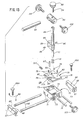
- Figure 1 is a front perspective view of an illustrative multi-axial work support and positioning device for use in the manufacture and repair of jewelry.
- Fig. 1A is an enlarged transverse vertical sectional view taken through the ring mandrel in the plane of the line 1A-1A and illustrating the 360 degree rotational adjustment of the mandrel.
- Fig. 2 is a fragmentary perspective view illustrating the telescoping relationship between the central depending stem of the platen and the upstanding support column associated therewith.
- Fig. 3 is an enlarged horizontal sectional view taken through the central depending shaft, upstanding column, and locking means of the work support and positioning device.
- Fig. 4 is an enlarged fragmentary vertical sectional view taken in the plane of the line 4-4 and detailing the pin and 90 degree groove indexing means.
- Fig. 5 is a fragmentary perspective view showing an engraving head and its adjustable supporting means connected to the platen.
- Fig. 6 is an enlarged vertical sectional view taken through the platen in the plane of the line 6-6 and showing the clamp used for the inner end of the ring mandrel or, alternatively, for the inner end of the support for the shellac stick, ring clamp, or engraving head.
- Fig. 7 is an enlarged, fragmentary vertical sectional view taken through the bench pin in the plane of the line 7-7.
- Fig. 8 is an enlarged, fragmentary view partially in section showing the adjustable clamp for the vise on the platen.
- Fig. 9 is an enlarged, fragmentary vertical sectional view taken in the plane of the line 9-9 in Fig. 8.
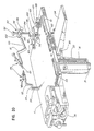
- Figure 10 is a perspective view illustrating a three directional precision positioning device for handling small jewelry components, the device being mounted adjacent one edge of the platen.
- Fig. 11 is an enlarged vertical sectional view taken through the positioning device of Fig. 10 in the plane of the line 11-11.
- Fig. 12 is an enlarged horizontal sectional view taken in the plane of the line 12-12 in Fig. 10.
- Fig. 13 is an exploded perspective view illustrating the components of the precision positioning device of Fig. 10.
- Fig. 14 is an exploded view partially in section illustrating the holder for a shellac pan or ring clamp.
- Fig. 15 is an enlarged plan view, partially in section, illustrating the holder for a shellac pan.
- Fig. 16 is a plan view illustrating the manner of holding the shellac pan by means of retaining screws.
- Fig. 17 is an exploded elevational view of the shellac pan holder and the pan.
- Fig. 18 is an enlarged, fragmentary perspective view showing a ring secured in solidified shellac in the pan and holder in preparation for work.
- Fig. 19 is a perspective view of a ring clamp mountable in an arm secured to the platen in preparation for work on a ring.
- Fig. 20 is an enlarged front perspective view of the platen and associated micro positioner illustrating the precision alignment of two tweezer work holders by means of the micro positioner.
- While the present invention is susceptible of various modifications and alternative constructions, there is no intention to limit the invention to the specific forms illustrated and described herein. On the contrary, the intention is to cover all modifications and alternative constructions falling within the spirit and scope of the invention as set forth in the appended claims.
- Referring more specifically to Figs. 1 through 5, the invention is there exemplified in a jeweler's multi-axial work support and positioning device 10 for use in the manufacture and repair of jewelry. The device 10 comprises a
platen 11 which in the present instance is of generally rectangular form with slightly rounded corners. Theplaten 11 has a central dependingpivot shaft 12 with anintegral hub 14 at the top which is secured to the underside of the platen as by means of screws. Thepivot shaft 12 telescopically engages anaxial bore 15 inupstanding column 16 which is fixed to abase 18. The column base, which may be square or some other shape providing the necessary stability, is mounted on an underlying support surface such as a work table (not shown) and secured in place by hold downbolts 19. - The
platen 11 may be raised or lowered axially of thecolumn 16 and retained in any elevated vertical position by means of theshaft clamp lever 20 on the column. Theplaten 11 may also be retained in any given angular position by means of theclamp lever 20. To carry out the above functions, theclamp lever 20 is associated with a pair ofbushings 21, 22 and ascrew 24 rigidly fixed to thelever 20. The bushing 21 is disposed in threaded engagement with thescrew 24. When theclamp lever 20 is turned clockwise, thescrew 24 squeezes thebushings 21, 22 against thepivot shaft 12, restraining theshaft 12 against any axial or any rotational movement relative to the column bore 15. - The
column 16 andpivot shaft 12 may also include additional means for relative vertical and angular positioning. For this purpose, thepivot shaft 12 may be provided with one row of axially spaced diametrical holes 25, any one of which may accept adiametrical positioning pin 26. The diameter of thepin 26 may be on the order of 0.187 inch. The axial location of the pin on the pivot shaft will determine the height of theplaten 11 relative to thecolumn 16. When theclamp 20 is relaxed, thepositioning pin 26 will engage the upper end of thecolumn 16 and the platen can be turned to the desired angular position at the height dictated by thepin 26 and top surface of the column. Engagement of theclamp 20 will hold the platen in that position. - For additional convenience in angular positioning of the platen, the top surface of the
column 16 may include a pair of relatively shallow V-grooves 28, 29 intersecting at an angle of 90 degrees. With the cooperation of thepin 26, this arrangement provides four distinct angular positions about the axis of thepivot shaft 12 andcolumn 16. The platen can be quickly shifted from one such angular position to any other and then locked in the desired position by theshaft clamp lever 20. - The
platen 11 has four sides, 30, 31, 32 and 33 each equipped respectively with a specific auxiliary device for working on jewelry. Oneside 30 of the platen, which in this instance happens to be longer than the twoadjacent sides bench pin 34. The latter is shown as a wedge shaped wood block which may have a V-shaped slot for use in temporarily holding a part to permit a filing or other tooling operation. Thebench pin 34 is held against the underside of the platen by thebar clamp 35 and associated screws. Thebar clamp 35 is designed to accommodate all sizes of bench pin. - The
shorter side 31 of the platen supports asmall vise 36 which may be adjusted throughout a 180 degree rotational path (Figs. 1,8,9). The vise includes an inwardly projecting adjustingclamp 38 which slidably and rotationally engages a mountingbar 39 of circular cross-section fixed to the underside of theplaten 11. The clamp is actuated byhandle 40. - The other
longer side 32 of the platen has located thereon a ring size mandrel 41 (Figs. 1,1A,6). Theinner end 42 of the latter has a pair of radially spacedflats 43 and is secured to the underside of the platen by means of a V-type mandrel clamp 44. The clamp comprises a V-block 45 swivel mounted on the underside of theplaten 11, a pair of laterally spacedblocks clamp bar 48 fixed to the blocks. Aknurled knob 50 has a threadedstem 51 which engages a tapped hole in the clamp bar and aligned threadedsleeve 49, pressing themandrel end 42 against theswivel block 45. Prior to tightening theknob 50, the mandrel and swivel block may be set to the desired angular position within the range of approximately 160 degrees in a horizontal plane. Theknob 50 is then tightened, securing the mandrel in the desired angular position. - In place of the
ring mandrel 41, anengraving head 54 may be mounted in the ring mandrel clamp 44. The engraving head has aclamp engaging section 42A withflats 43 substantially identical to that of theinner end 42 of the mandrel. The clamp engaging section may be secured in the clamp 44 by means of theknurled knob 50. A generallyU-shaped bracket 55 is fixed at one end of thesection 42A. The opposite end of thebracket 55 terminates in a captive ball 56 which provides a swivel support for theengraving head 54. - Adjacent the remaining
shorter side 33 of the platen, a socket bore 57 is located which receives an adjustable mounting 58 for a universal soldering clamp. The platen also includes two additional socket bores 57, oneadjacent side 31 and the otheradjacent side 32 for receiving additional universal soldering clamps. This permits the work to be held in any position or attitude to permit soldering of complex and minute pieces of jewelry. - The
platen 11 is also formed with a series ofrecesses longer side 30. It may also have additional recesses (not shown) adjacent its other longer side. The recesses are useful for collecting filings of precious metal or holding minute tools or components like stones and pearls incident to working on jewelry. - In order to facilitate the performance of minute soldering operations on delicate pieces of jewelry, a
micro work positioner 62 is utilized (Figs. 10-13). The micro work positioner in the present instance is securely mounted on top of the platen adjacent theshorter end 33 thereof opposite from thevise 36. Thework positioner 62 comprises a base 64 defined by a pair of opposed mountingblocks 65 connected by a pair of laterally spaced guide bars 66. The ends of the guide bars are slip fit into correspondingbores 67 in the mounting blocks and retained in place byset screws 69. Each mountingblock 65 has a centrally locatedvertical bore 68 which receives ananchor screw 68A. Eachscrew 68A has a large knurled head and engages a threaded bore in theplaten 11, thereby anchoring thework positioner 62 on the platen. - The
micro work positioner 62 includes a hollow, generallyrectangular slide 70 formed with a pair of laterally spaced bores 71 which slidably engage the guide bars 66 and permit the slide to be moved longitudinally of thebars 66 between the mounting blocks 65 (Figs. 10, 12, 13, 20). Theslide 70 is of inverted, generally U-shaped cross section in a direction perpendicular to the guide bars 66. It has a largecentral cavity 72 of generally rectangular shape and which is intersected by a pair of relatively short, laterally spaced guide bars 74 spaced vertically above the longer guide bars 66. Asecond slide 75 of stepped configuration is formed with aplate portion 76 generally coextensive with, and overlying, the top face of theslide 70. Theslide 75 has a generally rectangular dependingportion 78 integral with theplate portion 76 and somewhat smaller than the width ofcavity 72 in a direction parallel to the guide bars 66. The dependingportion 78 of thesecond slide 75 is rigidly connected to the short guide bars 74 as byset screws 79 in threaded bores 80. The short guide bars 74 and slide 75 are mounted for axial movement in unison relative to alignedbores 73 of the slide 70 (Fig. 13). - The
work positioner 62 further comprises an upstandingtubular guide 81 fixed as by means of a press fit within avertical bore 82 in the central portion of the second slide 75 (Figs. 11-13). Thetubular guide 81 is further secured in thebore 82 by means of set screw 77 and threadedbore 77A which communicates with thebore 82. Surrounding thetubular guide 81 is atelescoping sleeve 84 fixed to anoblong arm 85 as by means of a press fit. Thearm 85 is precluded from turning by anupstanding pin 87 press fit within abore 88 in theslide 75, and telescopically extending into an aligned bore 89 in the oblong arm. Two diametrically opposed setscrews 86, one from each side of theoblong arm 85, are adjusted to positionpin 87 in the center of thebore 89 with all relative lateral motion eliminated. The set screws 86 do, however, permit thearm 85 to move freely in a vertical direction with thesleeve 84. - A biasing
spring 91 is housed within an enlarged bore surrounding thetubular guide 82 and exerts an upward biasing force upon theoblong arm 85 andtelescoping sleeve 84. The degree of vertical adjustment of thetelescoping sleeve 84 relative to the fixedtubular guide 81 is controlled by means ofadjustment knob 92 at the top of theguide 81 andsleeve 84. Theknob 92 has a threadedstem 94 which engages threads on the inner bore of thetubular guide 81 to control the motion of thesleeve 84 along theguide 81. - For the purpose of supporting the
work holder 95, thework positioner 62 has across arm 96 adjustably mounted on the telescoping sleeve 84 (Figs. 10, 11, 13). Thecross arm 96 has atransverse bar 98 adjustably supported in a bore through the cross arm. Thebar 98 may be secured in a given position by means of clampingknob 99 and its threaded arm. One end of thebar 98 has a double swivel fitting 100 which supports the work holding tweezer fingers 101 (Fig. 10). - Adjustment of the
micro work positioner 62 may be initiated by starting with the approximate positioning devices. First, theslide 70 may be shifted manually in a horizontal direction along the guide bars 66 to a desired position. Next, thecross arm 96 may be positioned manually in a vertical direction on thetelescoping sleeve 84 and secured there by tightening the coarsevertical adjustment knob 102. Thetransverse bar 98, swivel fitting 100, thework holder 101 may then be adjusted and secured by tightening the adjustingknob 99. The fine vertical adjustment is then made by turning theknob 92 in the proper direction to align the work holder vertically with another work holder. The fine horizontal adjustment is achieved by turning finehorizontal adjusting knob 103 which operates against the pressure of biasingspring 104 to align the work holder horizontally with the other work holder. - Referring next to Figs. 14 and 15, there is shown a
swivel fixture 105, the first figure an exploded view and the second an assembled view. Thefixture 105 comprises anannular head 106 for receiving a work support unit such as the shellac pan assembly 108 (Figs. 16-18) or the ring clamp assembly 109 (Fig. 19). - The
fixture 105 has a mountingstem 110 similar to thestem 42 of the ring mandrel, or the stem 43A of the engraving head bracket (Figs. 14, 15, 18). The mountingstem 110, like the others, has a pair ofopposed flats 43 for engagement by the mandrel V-clamp 44 on the underside of the platen. Thehead 106 has a reduced diameter extension 111 rotatably engaged within abore 112 in thestem 110 and retained therein by means oftension screw 113 andbias spring 114. The bias is sufficient to hold thefixture head 106 in a given angular position which can be easily overcome manually. When moved by the user to a desired angular position, which may be any angle within 360 degrees, thehead 106 may be locked in that position by means ofclamp screw 115. - The shellac pan assembly 108 (Figs. 16, 17) is fashioned as a round metal holder comprising a heavy depending
handle 116 surmounted by a cylindrical hub 118. The latter has arim 119 of somewhat larger diameter with a shallowcylindrical recess 120 defined therein. Therecess 120 is adapted to hold a shallowcylindrical pan 121 containing a body ofshellac 122. Thepan 121 has aperipheral groove 124 formed adjacent its base. Threeknurled retaining screws 125 extending radially through therim 119 engage thegroove 124 to secure the pan in therecess 120. - In order to use the
pan assembly 108, the holder without the shellac pan is inserted into theannular head 106 of the fixture 105 (Fig. 18). The cylindrical hub 118 has a snug sliding fit with theaperture 126 of the annular head and the lower face of therim 119 seats firmly on the top face of the head. The mountingstem 110 of the fixture is inserted into the V-type mandrel clamp and the latter is tightened by theknob 50. Thepan 121, which is made of aluminum alloy for rapid heat conductivity, and which has previously been filled with shellac that has solidified, is now quickly heated and the piece of jewelry to be worked upon is set partially into the shellac. When the shellac has cooled, the piece is securely held in place and the pan is inserted into thecylindrical recess 120 in the holder. The retaining screws 125 are tightened to hold the pan in place. Thefixture 105 is turned to the angular position desired by the jeweler and clamped in that position by thescrew 115. The preparation for work by the jeweler is now complete. - When the jeweler has finished his work on the piece, the knurled screws 125 are loosened and the aluminum alloy pan is removed from the cylindrical hub 118 of the holder. The pan is then heated and the shellac softens quickly, enabling the jeweler to remove the piece without difficulty. The small amount of shellac residue on the piece is easily removed with alcohol.
- Turning next to Fig. 19, a
ring clamp 128 is there shown for use in thework fixture 105 described earlier herein. The ring clamp has ahandle 129 surmounted by acylindrical hub 130 with an aperture for receiving the upper end portion of the handle. The latter is retained in thehub 130 by means of setscrew 131. The upper portion of thehub 130 is also formed with arim 132 of somewhat larger diameter than the lower portion. Thehandle 129 has a large knurled-head screw 134 projecting from its lower end and which, when tightened, brings the clampingjaws 135 together holding the ring securely in place. - The
ring clamp 128, with the ring in place, may then be inserted into theannular head 106 of theswivel fixture 105 and angularly adjusted as in the case of theshellac pan assembly 108. When thehead 106 andring clamp 128 have reached the desired angular position, thehead 106 may be clamped in that position byclamp screw 115 and the ring is ready to be worked upon by the jeweler. Upon completion of the work, thering clamp 128 is opened by loosening theclamp screw 134, the ring is removed from thejaws 135, and thering clamp 128 is removed from theannular head 106.
Claims (18)
1. A multi-axial work support and positioning device for use in the manufacture and repair of jewelry, comprising, in combination:
(a) a base adapted for rigid mounting on an underlying support;
(b) an upstanding column fixed to said base;
(c) a work platen adapted to hold an assortment of fixtures for manufacturing and repairing jewelry, said fixtures being mounted about the periphery of said platen leaving a clear deck area within said periphery;
(d) a depending member fixed to said platen mounted in telescoping relation with said column and being rotatable with respect thereto;
(e) means for clamping said platen in any give vertical position within its range of vertical movement; and
(f) means for clamping said platen in any given angular position within its range of rotational movement.
2. A multi-axial work support and positioning device as set forth in claim 1, wherein said fixtures are mounted on the underside of the periphery of said platen.
3. The combination set forth in claim 1, wherein said depending member is a pivot shaft and said column is of annular cross section and telescopically engages said shaft.
4. The combination recited in claim 3, wherein said pivot shaft is formed with a series of diametrical holes spaced axially thereon, a transverse pin is adapted to be positioned in any one of said diametrical holes, and one or more diametrical grooves are formed in the top surface of said column to engage said pin and locate said platen in a predetermined angular position.
5. The combination set forth in claim 4, wherein said platen and said pivot shaft may be clamped in a predetermined angular position defined by said pin and a diametrical groove on the top of said column.
6. The combination recited in claim 2, wherein one of said fixtures is a bench pin clamped to the underside of said platen.
7. The combination set forth in claim 2, wherein one of said fixtures is a vise adjustably mounted for pivotal adjustment in a clamp on the underside of said platen and capable of positioning at any point in an arc of 180 degrees above the longitudinal axis of said clamp.
8. The combination recited in claim 2, wherein one end of a ring mandrel is adjustably clamped to the underside of said platen and is positionable at any selected point in a horizontal plane within an angle of approximately 160 degrees.
9. The combination recited in claim 2, wherein a generally U-shaped bracket for an engraving head may be clamped to the underside of said platen in place of said ring mandrel.
10. The combination of a multi-axial work support and positioning device having a platen with a micro work positioner for delicate soldering or other operations on jewelry and comprising:
(a) a base mounted on said platen;
(b) a first slide movable longitudinally of said base;
(c) a second slide movable transversely of said first slide;
(d) an upright stem assembly mounted on said second slide;
(e) a cross arm mounted on said stem assembly and manually adjustable therealong;
(f) a tweezer micro clamp connected to said cross arm;
(g) micro adjustment means for precisely positioning said micro clamp along a vertical axis; and
(h) micro adjustment means for precisely positioning said micro clamp along an intersecting horizontal axis.
11. The combination set forth in claim 10 wherein said upright stem assembly comprises a tubular guide rigidly fixed to said second slide and a telescoping sleeve is movable axially of said tubular guide under control of micro adjustment means and an opposed biasing means.
12. The combination recited in claim 11 wherein said telescoping sleeve is rigidly connected to an oblong arm, the latter being restrained against rotation by means of a sliding connection with said second slide.
13. The combination of a multi-axial work support and positioning device having a platen with a micro work positioner for delicate soldering or other operations on jewelry and comprising:
(a) a base mounted on said platen;
(b) a first slide movable longitudinally of said base;
(c) a second slide movable transversely of said first slide;
(d) a nonrotatable upright stem assembly mounted on said second slide;
(e) a cross arm mounted on said stem assembly and manually adjustable therealong;
(f) A tweezer micro clamp connected to said cross arm;
(g) micro adjustment means on said upright stem assembly for precisely positioning said micro clamp along a vertical axis; and
(h) micro adjustment means on said second slide for precisely positioning said micro clamp along an intersecting horizontal axis.
14. The combination set forth in claim 13, wherein said micro adjustment means on said upright stem is a knob threadedly engaging said tubular guide and abuttingly engaging the uppermost end of said telescoping sleeve against the force of an opposing biasing spring.
15. The combination of a multi-axial work support and positioning device having a platen with a micro work positioner thereon for delicate soldering or other operations on jewelry and comprising:
(a) a base mounted on said platen;
(b) a first slide movable on guide bars longitudinally of said base;
(c) a second slide movable on guide bars transversely of said first slide;
(d) an upright tubular guide stem mounted on said second slide;
(e) a telescoping sleeve slidably mounted on said tubular guide;
(f) an oblong arm fixed to said telescoping sleeve and urged upward by a resilient biasing means;
(g) means permitting said oblong arm and telescoping sleeve to move vertically but precluding horizontal motion thereof;
(h) a cross arm mounted on said telescoping sleeve and manually adjustable therealong;
(i) a tweezer micro clamp connected to said cross arm;
(j) a first micro adjustment knob threadedly engaging said tubular guide and abuttingly engaging the adjacent end of said telescoping sleeve for precisely positioning said micro clamp along a vertical axis; and
(k) a second micro adjustment knob threadedly engaging said first slide and moving said second slide against resilient biasing means for precisely positioning said micro clamp along an intersecting horizontal axis.
16. The combination of a multi-axial work support and positioning device having a platen rotatable about and positionable along a vertical axis, with a swivel fixture comprising:
(a) a shellac pan holder having a depending handle and detachably mounted in said swivel fixture for rotational adjustment through an angle of 360 degrees;
(b) means defining a relatively shallow recess in said holder;
(c) a shellac pan with a body of shellac therein; said pan being telescopically mounted in said shallow recess;
(d) said shellac pan being formed of aluminum alloy material for good heating and cooling characteristics;
(e) and means for detachably securing said shellac pan within said holder recess to permit rapid heating of said shellac to receive a jewelry workpiece and rapid cooling of said shellac to hold the workpiece in place.
17. The combination set forth in claim 16, wherein said shellac pan with a completed workpiece may be rapidly heated to permit removal of said workpiece from said shellac.
18. In a multi-axial work support and positioning device having a rotatable platen, the combination comprising:
(a) a swivel fixture having a mounting stem clamped to said platen, said mounting stem having a longitudinal axis;
(b) an annular head having a central aperture therein and swivel mounted about said longitudinal axis, said head being positionable at any selected angle throughout 360 degrees;
(c) a generally cylindrical hub having a shallow recess therein;
(d) a rim on said hub overlying said annular head in abutting relationship with same;
(e) a handle mounted in depending relation with said hub;
(f) a shellac pan formed of aluminum alloy with good heating and cooling characteristics;
(g) a body of shellac in said shellac pin for holding a jewelry workpiece; and
(h) means for detachably securing said shellac pan within said recess of said hub.
Applications Claiming Priority (2)
| Application Number | Priority Date | Filing Date | Title |
|---|---|---|---|
| US16618288A | 1988-03-10 | 1988-03-10 | |
| US166182 | 1993-12-10 |
Publications (2)
| Publication Number | Publication Date |
|---|---|
| EP0335126A2 true EP0335126A2 (en) | 1989-10-04 |
| EP0335126A3 EP0335126A3 (en) | 1991-10-16 |
Family
ID=22602151
Family Applications (1)
| Application Number | Title | Priority Date | Filing Date |
|---|---|---|---|
| EP19890103670 Withdrawn EP0335126A3 (en) | 1988-03-10 | 1989-03-02 | Jeweler's multi-axial work support and positioning device |
Country Status (1)
| Country | Link |
|---|---|
| EP (1) | EP0335126A3 (en) |
Cited By (8)
| Publication number | Priority date | Publication date | Assignee | Title |
|---|---|---|---|---|
| FR2682015A1 (en) * | 1991-10-04 | 1993-04-09 | Hattori Seiko Co Ltd | METHOD AND APPARATUS FOR REPAIRING AND ADJUSTING THE LENGTH OF A BRACELET |
| US8587660B2 (en) | 2010-07-30 | 2013-11-19 | General Electric Company | Image recording assemblies and coupling mechanisms for stator vane inspection |
| US8602722B2 (en) | 2010-02-26 | 2013-12-10 | General Electric Company | System and method for inspection of stator vanes |
| US8667856B2 (en) | 2011-05-20 | 2014-03-11 | General Electric Company | Sensor assemblies and methods of assembling same |
| CN107571048A (en) * | 2017-09-06 | 2018-01-12 | 深圳市贵峰精密有限公司 | The positioner and localization method of a kind of workpiece |
| CN108669724A (en) * | 2018-06-07 | 2018-10-19 | 杭州电子科技大学 | Four station diplopore illiciumverum crystal pearls of one kind series winding fixture and its auxiliary series-mounting |
| US11383356B1 (en) | 2021-02-16 | 2022-07-12 | Dennis J. Montilepre | System and method for easy rotational jewelry metal clamp |
| CN116441839A (en) * | 2023-06-14 | 2023-07-18 | 艾瑞(成都)排放控制技术有限公司 | End cone welding fixture |
Citations (18)
| Publication number | Priority date | Publication date | Assignee | Title |
|---|---|---|---|---|
| US456891A (en) * | 1891-07-28 | Walliace b | ||
| US709399A (en) * | 1902-01-07 | 1902-09-16 | Emmert Mfg Company | Vise. |
| US2221108A (en) * | 1939-05-20 | 1940-11-12 | Louis C Rathbun | Soldering device |
| US2276819A (en) * | 1939-12-26 | 1942-03-17 | Teletype Corp | Aligning fixture |
| DE811065C (en) * | 1948-10-02 | 1951-08-16 | Gerhard Geiger Jun | Device for holding parts, e.g. B. when welding, soldering, etc. |
| DE929321C (en) * | 1952-02-17 | 1955-06-23 | Fella Werke Gmbh | Transportable work device similar to a workbench |
| US3168893A (en) * | 1962-12-26 | 1965-02-09 | Frank O Johnson | Semiprecious stone cutting vise |
| US3484095A (en) * | 1968-02-08 | 1969-12-16 | Maurice S Park | Jeweler's bench work clamp |
| DE7630392U1 (en) * | 1976-09-29 | 1977-02-10 | Rohde & Schwarz, 8000 Muenchen | Auxiliary soldering device |
| AT356033B (en) * | 1976-12-30 | 1980-04-10 | Moser Kurt | ADDITIONAL DEVICE FOR WORK TABLES OR WORKED MACHINES |
| DE3002398A1 (en) * | 1979-02-12 | 1980-08-21 | Dachauer Wilhelm | Positionable vice work plate - has clamp with prismatic groove allowing axial- and radial adjustment on tubular cross piece |
| US4291869A (en) * | 1971-08-02 | 1981-09-29 | Tekron Licensing B.V. | Workbench |
| US4295640A (en) * | 1980-01-07 | 1981-10-20 | Merrell Charles E | Jeweler's tool |
| WO1982000574A1 (en) * | 1980-08-14 | 1982-03-04 | J Robertson | Decorative articles |
| US4418901A (en) * | 1981-04-22 | 1983-12-06 | International Design Corporation | Vise system |
| US4555099A (en) * | 1983-06-17 | 1985-11-26 | Hilton (Products) Limited | Workbenches |
| US4595186A (en) * | 1984-12-20 | 1986-06-17 | Reed Richard A | Rotating welding fixture |
| EP0218546A1 (en) * | 1985-08-30 | 1987-04-15 | Centre Suisse D'electronique Et De Microtechnique S.A. | Micropositioning device |
-
1989
- 1989-03-02 EP EP19890103670 patent/EP0335126A3/en not_active Withdrawn
Patent Citations (18)
| Publication number | Priority date | Publication date | Assignee | Title |
|---|---|---|---|---|
| US456891A (en) * | 1891-07-28 | Walliace b | ||
| US709399A (en) * | 1902-01-07 | 1902-09-16 | Emmert Mfg Company | Vise. |
| US2221108A (en) * | 1939-05-20 | 1940-11-12 | Louis C Rathbun | Soldering device |
| US2276819A (en) * | 1939-12-26 | 1942-03-17 | Teletype Corp | Aligning fixture |
| DE811065C (en) * | 1948-10-02 | 1951-08-16 | Gerhard Geiger Jun | Device for holding parts, e.g. B. when welding, soldering, etc. |
| DE929321C (en) * | 1952-02-17 | 1955-06-23 | Fella Werke Gmbh | Transportable work device similar to a workbench |
| US3168893A (en) * | 1962-12-26 | 1965-02-09 | Frank O Johnson | Semiprecious stone cutting vise |
| US3484095A (en) * | 1968-02-08 | 1969-12-16 | Maurice S Park | Jeweler's bench work clamp |
| US4291869A (en) * | 1971-08-02 | 1981-09-29 | Tekron Licensing B.V. | Workbench |
| DE7630392U1 (en) * | 1976-09-29 | 1977-02-10 | Rohde & Schwarz, 8000 Muenchen | Auxiliary soldering device |
| AT356033B (en) * | 1976-12-30 | 1980-04-10 | Moser Kurt | ADDITIONAL DEVICE FOR WORK TABLES OR WORKED MACHINES |
| DE3002398A1 (en) * | 1979-02-12 | 1980-08-21 | Dachauer Wilhelm | Positionable vice work plate - has clamp with prismatic groove allowing axial- and radial adjustment on tubular cross piece |
| US4295640A (en) * | 1980-01-07 | 1981-10-20 | Merrell Charles E | Jeweler's tool |
| WO1982000574A1 (en) * | 1980-08-14 | 1982-03-04 | J Robertson | Decorative articles |
| US4418901A (en) * | 1981-04-22 | 1983-12-06 | International Design Corporation | Vise system |
| US4555099A (en) * | 1983-06-17 | 1985-11-26 | Hilton (Products) Limited | Workbenches |
| US4595186A (en) * | 1984-12-20 | 1986-06-17 | Reed Richard A | Rotating welding fixture |
| EP0218546A1 (en) * | 1985-08-30 | 1987-04-15 | Centre Suisse D'electronique Et De Microtechnique S.A. | Micropositioning device |
Cited By (11)
| Publication number | Priority date | Publication date | Assignee | Title |
|---|---|---|---|---|
| FR2682015A1 (en) * | 1991-10-04 | 1993-04-09 | Hattori Seiko Co Ltd | METHOD AND APPARATUS FOR REPAIRING AND ADJUSTING THE LENGTH OF A BRACELET |
| FR2683125A1 (en) * | 1991-10-04 | 1993-05-07 | Hattori Seiko Co Ltd | TOOL FOR REPAIRING AND ADJUSTING THE LENGTH OF A BRACELET. |
| US8602722B2 (en) | 2010-02-26 | 2013-12-10 | General Electric Company | System and method for inspection of stator vanes |
| US8587660B2 (en) | 2010-07-30 | 2013-11-19 | General Electric Company | Image recording assemblies and coupling mechanisms for stator vane inspection |
| US8667856B2 (en) | 2011-05-20 | 2014-03-11 | General Electric Company | Sensor assemblies and methods of assembling same |
| CN107571048A (en) * | 2017-09-06 | 2018-01-12 | 深圳市贵峰精密有限公司 | The positioner and localization method of a kind of workpiece |
| CN108669724A (en) * | 2018-06-07 | 2018-10-19 | 杭州电子科技大学 | Four station diplopore illiciumverum crystal pearls of one kind series winding fixture and its auxiliary series-mounting |
| CN108669724B (en) * | 2018-06-07 | 2023-10-20 | 杭州电子科技大学 | Four-station double-hole octagonal crystal bead serial connection clamp and auxiliary serial connection method thereof |
| US11383356B1 (en) | 2021-02-16 | 2022-07-12 | Dennis J. Montilepre | System and method for easy rotational jewelry metal clamp |
| CN116441839A (en) * | 2023-06-14 | 2023-07-18 | 艾瑞(成都)排放控制技术有限公司 | End cone welding fixture |
| CN116441839B (en) * | 2023-06-14 | 2023-08-22 | 艾瑞(成都)排放控制技术有限公司 | End cone welding fixture |
Also Published As
| Publication number | Publication date |
|---|---|
| EP0335126A3 (en) | 1991-10-16 |
Similar Documents
| Publication | Publication Date | Title |
|---|---|---|
| EP0925154B1 (en) | Dual adjustable vise | |
| CA2635614C (en) | Grinding and honing fixture with clamping jaws | |
| US7398965B2 (en) | Holder for supporting workpiece in a fixed location pivotal about dual axes | |
| EP0335126A2 (en) | Jeweler's multi-axial work support and positioning device | |
| US3394389A (en) | Piece positioning devices | |
| EP0019902B1 (en) | Workpiece support arrangement | |
| US4927126A (en) | Precision vise | |
| US4744552A (en) | Craftsman's jewelry support tool | |
| US8087858B2 (en) | Vise-mounted milling machine collet indexer | |
| EP0003832B1 (en) | Workpiece supporting and clamping arrangement | |
| US4830350A (en) | Universal clamping device with multi-purpose clamping surfaces | |
| EP0019903B1 (en) | A swivel vise | |
| JPS60213451A (en) | Angle adjuster for vise | |
| US2856799A (en) | Support for small tools | |
| US4807861A (en) | Swivel vise | |
| CN212145424U (en) | Top clamp tool | |
| US3980287A (en) | Combination vise, V-block and drill jig workholder | |
| US4976418A (en) | Boring bar-cutter head fixture | |
| US4327902A (en) | Coaxial workpiece arranger for rotary work holders of contour turning machines | |
| US4715148A (en) | Gem faceting machine | |
| CN209774034U (en) | Universal flat tongs with replaceable chuck | |
| US5984160A (en) | Multipurpose craftsman's portable workstation | |
| US5096169A (en) | Setting tool | |
| GB2370250A (en) | Automated engraving apparatus | |
| CN219521256U (en) | Multi-point clamping tool for structural part |
Legal Events
| Date | Code | Title | Description |
|---|---|---|---|
| PUAI | Public reference made under article 153(3) epc to a published international application that has entered the european phase |
Free format text: ORIGINAL CODE: 0009012 |
|
| AK | Designated contracting states |
Kind code of ref document: A2 Designated state(s): CH DE FR GB LI |
|
| PUAL | Search report despatched |
Free format text: ORIGINAL CODE: 0009013 |
|
| AK | Designated contracting states |
Kind code of ref document: A3 Designated state(s): CH DE FR GB LI |
|
| STAA | Information on the status of an ep patent application or granted ep patent |
Free format text: STATUS: THE APPLICATION IS DEEMED TO BE WITHDRAWN |
|
| 18D | Application deemed to be withdrawn |
Effective date: 19911003 |