EP0334820B1 - Self-focusing optical system for spectrophotometric measurements and the like, with optical fiber sensors - Google Patents
Self-focusing optical system for spectrophotometric measurements and the like, with optical fiber sensors Download PDFInfo
- Publication number
- EP0334820B1 EP0334820B1 EP89830126A EP89830126A EP0334820B1 EP 0334820 B1 EP0334820 B1 EP 0334820B1 EP 89830126 A EP89830126 A EP 89830126A EP 89830126 A EP89830126 A EP 89830126A EP 0334820 B1 EP0334820 B1 EP 0334820B1
- Authority
- EP
- European Patent Office
- Prior art keywords
- cavity
- lens
- optical fiber
- lenses
- reflecting surface
- Prior art date
- Legal status (The legal status is an assumption and is not a legal conclusion. Google has not performed a legal analysis and makes no representation as to the accuracy of the status listed.)
- Expired - Lifetime
Links
- 230000003287 optical effect Effects 0.000 title claims abstract description 24
- 239000013307 optical fiber Substances 0.000 title claims abstract description 23
- 238000002798 spectrophotometry method Methods 0.000 title claims abstract description 7
- 230000005855 radiation Effects 0.000 claims description 17
- 238000001514 detection method Methods 0.000 claims description 4
- 239000000835 fiber Substances 0.000 description 13
- 239000000126 substance Substances 0.000 description 9
- 238000005259 measurement Methods 0.000 description 7
- 230000014509 gene expression Effects 0.000 description 4
- 239000007789 gas Substances 0.000 description 2
- 239000007788 liquid Substances 0.000 description 2
- 239000011159 matrix material Substances 0.000 description 2
- 238000002835 absorbance Methods 0.000 description 1
- 238000011481 absorbance measurement Methods 0.000 description 1
- 239000000203 mixture Substances 0.000 description 1
- KRTSDMXIXPKRQR-AATRIKPKSA-N monocrotophos Chemical compound CNC(=O)\C=C(/C)OP(=O)(OC)OC KRTSDMXIXPKRQR-AATRIKPKSA-N 0.000 description 1
- 230000009467 reduction Effects 0.000 description 1
Images

Classifications
-
- G—PHYSICS
- G02—OPTICS
- G02B—OPTICAL ELEMENTS, SYSTEMS OR APPARATUS
- G02B3/00—Simple or compound lenses
- G02B3/0087—Simple or compound lenses with index gradient
-
- G—PHYSICS
- G01—MEASURING; TESTING
- G01J—MEASUREMENT OF INTENSITY, VELOCITY, SPECTRAL CONTENT, POLARISATION, PHASE OR PULSE CHARACTERISTICS OF INFRARED, VISIBLE OR ULTRAVIOLET LIGHT; COLORIMETRY; RADIATION PYROMETRY
- G01J3/00—Spectrometry; Spectrophotometry; Monochromators; Measuring colours
- G01J3/02—Details
-
- G—PHYSICS
- G01—MEASURING; TESTING
- G01J—MEASUREMENT OF INTENSITY, VELOCITY, SPECTRAL CONTENT, POLARISATION, PHASE OR PULSE CHARACTERISTICS OF INFRARED, VISIBLE OR ULTRAVIOLET LIGHT; COLORIMETRY; RADIATION PYROMETRY
- G01J3/00—Spectrometry; Spectrophotometry; Monochromators; Measuring colours
- G01J3/02—Details
- G01J3/0205—Optical elements not provided otherwise, e.g. optical manifolds, diffusers, windows
- G01J3/0208—Optical elements not provided otherwise, e.g. optical manifolds, diffusers, windows using focussing or collimating elements, e.g. lenses or mirrors; performing aberration correction
Definitions
- the invention relates to an optical device for spectrophotometric measurements and the like, com prising a cavity for containing a sample to be measured; a reflecting surface disposed at one side of the cavity; and one optical fiber, arranged with one of its end-faces disposed at the opposite side of the cavity, for the conveyance of light radiation from an emitting source to said cavity and, after reflection onto the reflecting surface, from said cavity to devi ces for the detection of the modulated radiation.
- optical fiber sensors are based on spectrophotometric measurements carried out on liquids or gases.
- a suitably modulated and filtered light radiation is conveyed, via an optical fiber, into a cavity containing the medium, generally a liquid or a gas, to be tested for measurement.
- the measurements are based on the detection of absorbance variations in the medium under test, according to the variation of a specific physical or chemical quantity, such as, for example, the temperature, the concentration of a specific component of a mixture, or similar.
- the absorbance measurement with optical fibers is usually carried out by utilizing two fibers, one facing the other, one being used for illuminating the sample under test, i.e. for conveying the light radiation from the source to the measuring volume or cavity, and the other being used for picking up the light modulated by the substance under test interposed between the two fibers.
- the system comprises only one fiber facing a mirror, or a pair of fibers facing a mirror, the substance under test being interposed between said fibers and the mirror.
- the light radiation passes through the substance under test, is reflected by the mirror, passes through the substance under test again, and is then picked up by the same optical fiber which has emitted it or by a fiber adjacent to the latter.
- the fraction of light which is picked up is very small.
- even small disalignments of the two fibers or of the mirror cause significant reductions of efficiency.
- the object of the invention is to provide an optical system forming a cavity of the above mentioned type, which does not exhibit the above stated drawbacks and which, in particular, allows a high efficiency even in the case of errors of alignment of the optical elements making up the system.
- an optical device of the above mentioned type characterized in that said optical device further comprises: a first cylindrical graded refractive index lens (GRIN rod) connected to said one end-face of said optical fiber; and a second cylindrical graded refractive index lens disposed approximately coaxial to the first lens and spaced therefrom for delimiting, between the two facing end-faces of said lenses, said cavity for the sample to be measured; said reflecting surface being arranged on the other flat end-face of said second lens remote from the cavity; the light radiation reflected back by the reflecting surface being refocused on said one end-face of said optical fiber even when the two lenses are slightly angularly misaligned.
- GRIN rod cylindrical graded refractive index lens
- said lenses are quarter-pitch lenses and the reflecting surface is formed on the flat end-face of said second lens remote from the cavity.
- an optical system comprises an optical fiber 1 which is intended both for conveying the radiation to the measurement cavity and detecting the modulated radiation after it has passed through the substance on which the measurement is to be carried out.
- Said optical fiber 1 is connected to a first cylindrical refractive index gradient lens 3 (so-called graded index rod lens or GRIN rod), disposed coaxial to said optical fiber 1.
- a second cylindrical refraction index gradient lens 5 is disposed at a distance L from said first lens 3 .
- the two lenses 3 and 5 are received in corresponding seats of a housing (not shown) designed to define together with said lenses a cavity 7, inside which the substance is tested for the measurements.
- Said housing may be formed, for example, by a cylindrical hollow support closed at the two ends by lenses 3, 5 and having slots, in the central portion, for the passage of the substance under test.
- the two lenses 3, 5 are quarter-period, i.e. quarter-wave lenses so that each lens has its focus on its respective face.
- a mirror 9 is located able to reflect the beams coming from the optical fiber 1 after they have passed through the first lens 3, the cavity 7 and the second lens 5.
- the reflected rays pass through the elements 5, 7 and 3 a second time as described in more detail below, to be re-introduced in the fiber 1 and sent to a detection circuit.
- the coordinates of an output ray are obtainable from the coordinates of the input ray expressed as a column vector by multiplying it by the following matrix:
- any meridian ray entering the lens 5 and reflected by the mirror 9 comes out with the same angle of incidence and at a point diametrically opposite to the incidence point.
- r4 -r2 + 2Ltg ⁇ 3 + 2h ⁇ (1 - tg ⁇ tg ⁇ 3)
- tg ⁇ 0 tg ⁇ 1-2h ⁇ A- 2Ar1 ⁇ (L-h tg ⁇ )(n0/n)(1-tg2 ⁇ 1/2) [1+Ar1 2 ⁇ (1-(n0/n)2 ⁇ (1-tg2 ⁇ 1/2)2)] 1/2
- the quantity htg ⁇ is far less than L and, moreover: (n0/n) (1 - tg2 ⁇ 1/2) [1 + Ar1 2 ⁇ (1 - (n0/n)2 ⁇ (1 - tg2 ⁇ 1/2)2)] 1/2 ⁇ n0 n
- and for A(r1)2« 1 and k ⁇ 1 it thus follows that
Landscapes
- Physics & Mathematics (AREA)
- Spectroscopy & Molecular Physics (AREA)
- General Physics & Mathematics (AREA)
- Optics & Photonics (AREA)
- Investigating Or Analysing Materials By Optical Means (AREA)
- Testing Of Optical Devices Or Fibers (AREA)
- Optical Transform (AREA)
Abstract
Description
- The invention relates to an optical device for spectrophotometric measurements and the like, com prising a cavity for containing a sample to be measured; a reflecting surface disposed at one side of the cavity; and one optical fiber, arranged with one of its end-faces disposed at the opposite side of the cavity, for the conveyance of light radiation from an emitting source to said cavity and, after reflection onto the reflecting surface, from said cavity to devi ces for the detection of the modulated radiation.
- Various types of optical fiber sensors are based on spectrophotometric measurements carried out on liquids or gases. In these sensors, a suitably modulated and filtered light radiation is conveyed, via an optical fiber, into a cavity containing the medium, generally a liquid or a gas, to be tested for measurement. The measurements are based on the detection of absorbance variations in the medium under test, according to the variation of a specific physical or chemical quantity, such as, for example, the temperature, the concentration of a specific component of a mixture, or similar.
- The absorbance measurement with optical fibers is usually carried out by utilizing two fibers, one facing the other, one being used for illuminating the sample under test, i.e. for conveying the light radiation from the source to the measuring volume or cavity, and the other being used for picking up the light modulated by the substance under test interposed between the two fibers. In some cases the system comprises only one fiber facing a mirror, or a pair of fibers facing a mirror, the substance under test being interposed between said fibers and the mirror. In these cases, the light radiation passes through the substance under test, is reflected by the mirror, passes through the substance under test again, and is then picked up by the same optical fiber which has emitted it or by a fiber adjacent to the latter. In any case, owing to the divergence of the radiation beam emitted by the fiber, the fraction of light which is picked up is very small. Moreover, even small disalignments of the two fibers or of the mirror cause significant reductions of efficiency.
- These problems are all the more serious as the length of the cavity or volume inside which the measurement has to be performed increases. In some types of sensors and for particular measurements, in fact, it is necessary that the radiation emitted by the optical fiber goes through a cavity which is some decimetres long, at the opposite end of which - with respect to the end where the radiation input optical fiber is disposed - there must be arranged a flat mirror which is perfectly perpendicular to the axis of the optical fiber at the output section thereof, or a second optical fiber must be provided perfectly aligned with the first one. Even very small disalignments - due to assembly errors, work tolerances, thermal expansions, or the like - between one fiber and the other or between a fiber and the mirror, may cause the complete scattering of the beam.
- The object of the invention is to provide an optical system forming a cavity of the above mentioned type, which does not exhibit the above stated drawbacks and which, in particular, allows a high efficiency even in the case of errors of alignment of the optical elements making up the system.
- According to the invention, these and other advantages are obtained by an optical device of the above mentioned type, characterized in that said optical device further comprises: a first cylindrical graded refractive index lens (GRIN rod) connected to said one end-face of said optical fiber; and a second cylindrical graded refractive index lens disposed approximately coaxial to the first lens and spaced therefrom for delimiting, between the two facing end-faces of said lenses, said cavity for the sample to be measured; said reflecting surface being arranged on the other flat end-face of said second lens remote from the cavity; the light radiation reflected back by the reflecting surface being refocused on said one end-face of said optical fiber even when the two lenses are slightly angularly misaligned.
- In a particular embodiment of the invention, said lenses are quarter-pitch lenses and the reflecting surface is formed on the flat end-face of said second lens remote from the cavity.
- The invention will be better understood by following the description and the attached drawing, which shows a practical, non limiting example of the said invention. In the drawing:
- Fig. 1 shows a scheme of the optical system according to the invention;
- Fig. 2 shows diagrammatically the path of a light ray through the second lens of the optical system of Fig. 1; and
- Fig. 3 shows diagrammatically the path of a light ray throughout the optical system of Fig. 1.
- According to what is shown in the attached drawing, an optical system according to the invention comprises an
optical fiber 1 which is intended both for conveying the radiation to the measurement cavity and detecting the modulated radiation after it has passed through the substance on which the measurement is to be carried out. Saidoptical fiber 1 is connected to a first cylindrical refractive index gradient lens 3 (so-called graded index rod lens or GRIN rod), disposed coaxial to saidoptical fiber 1. At a distance L from said first lens 3 a second cylindrical refractionindex gradient lens 5 is disposed. The twolenses cavity 7, inside which the substance is tested for the measurements. Said housing may be formed, for example, by a cylindrical hollow support closed at the two ends bylenses lenses - On the end-face of the
second lens 5 opposite to cavity 7 amirror 9 is located able to reflect the beams coming from theoptical fiber 1 after they have passed through thefirst lens 3, thecavity 7 and thesecond lens 5. The reflected rays pass through theelements fiber 1 and sent to a detection circuit. - In the following description it is supposed that the two
lenses - For the study of the above described optical system the following variables are defined:
- r
- = distance from the lens axis of a light ray in a generic section of the lens:
- ϑ
- = inclination of a ray in a generic section of the lens;
- n(r)
- = n₀ (1 - A r²/2) index of refraction of the lens, wherein:
n₀ is the index of refraction on the lens axis and A is a quadratic constant of the index gradient. - For a cylindrical, quarter-wave refraction index gradient lens (i.e. a GRIN rod) such as the two
lenses 
- With reference to Fig. 2, denoting with "a" and "b" respectively the coordinates r and ϑ on input to and on output from the
lens 5 respectively, it can be demonstrated that the coordinates ra and ϑa are linked to the coordinates rb and ϑb through the following matrix equation:
- In conclusion, any meridian ray entering the
lens 5 and reflected by themirror 9 comes out with the same angle of incidence and at a point diametrically opposite to the incidence point. - With reference to Fig. 3 the following parameters are defined:
- r₁; ϑ₁ =
- coordinates of the
ray entering lens 3; - r₂; ϑ₃ =
- coordinates of the ray coming out from
lens 3; - r₃ =
- radial coordinate of the ray entering and coming out from
lens 5; - r₄; ϑ₄ = ϑ₃
- = coordinates of the
ray entering lens 3 on the side ofcavity 7; - r₀; ϑ₀ =
- coordinates of the ray coming out from the optical system.
- On the basis of trigonometric considerations, there is obtained:

r₂ and tgϑ₃ are expressed as functions of the coordinates of the ray entering the system by
and by
- Moreover:

- By combining the previous expressions together, there is obtained the analytic expression of tgϑ₀ as a function of r₁, tgϑ₁, L, h and tgα:

- The coordinate r₀ is given by:

- The angle ϑ₄ depends on ϑ₂ according to Snell's law:

where k is the ratio of the indexes of refraction: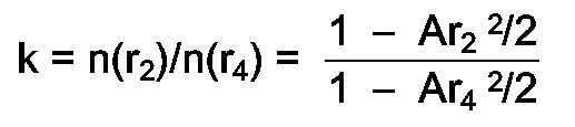
- Being
r₂ = tgϑ₁/√A and r₄ = -tgϑ₀/√A
there is obtained:
and tgϑ₄ is given by:
- Finally, since

there is obtained:
- In the application of refraction index gradient lenses (GRIN rods) according to the invention, the quantity htgα is far less than L and, moreover:

Which gives rise to the approximate expression:
and for A(r₁)²« 1 and k ≈ 1
it thus follows that
or
- From equations (I) and (II) it first follows that the angular disalignment between the two
lenses cosα≈ 1, which is a condition that can be always obtained if a fairly accurate assembling of the optical system is observed. From the expressions (I) and (II) it is also possible to determine how much the coordinates of the ray vary after this has gone through the optical system. If said system is applied to a cavity for spectrophotometric measurements, it can be typically assumed that:
√A = 0,25 mm⁻¹; h = 0,05 mm; L = 7 mm;
r₁ = 0,07 mm; tgϑ₁ = 0,13
and with these numerical values there is obtained:

- It thus follows that the coordinates r, ϑ of the output ray undergo only small variations with respect to the coordinates of the input ray. Thereby, practically all the radiation injected by the
optical fiber 1 into theoptical system - In conclusion, the system according to the invention exhibits the following advantages:
- 1. -
- only one fiber is used;
- 2. -
- the input radiation passes twice through the cavity;
- 3. -
- the beam in the cavity is collimated by the
lens 3 and not scattered as it happens in the current systems for optical spectrophotometric measurements using optical fibers, in which the beam fed into the measuring cavity comes out directly from the optical fiber and it is thus dispersed; - 4. -
- an error of disalignment of the two lenses does not give rise to energy losses, that is, the system is self-focusing;
- 5. -
- the energy losses due to scattering are less than 10%;
- 6. -
- it is also possible to use very thin fibers thereby obtaining even better efficiencies when the radial coordinate r₁ of the input ray is reduced, as it can be seen from equation (IIa).
Claims (2)
- An optical device for spectrophotometric measurements and the like, comprising a cavity (7) for containing a sample to be measured; a reflecting surface (9) disposed at one side of the cavity; and one optical fiber (1), arranged with one of its end-faces disposed at the opposite side of the cavity, for the conveyance of light radiation from an emitting source to said cavity and, after reflection onto the reflecting surface, from said cavity to devices for the detection of the modulated radiation, characterized in that said optical device further comprises: a first cylindrical graded refractive index lens (GRIN rod) (3) connected to said one end-face of said optical fiber (1); and a second cylindrical graded refractive index lens (GRIN rod) (5) disposed approximately coaxial to the first lens and spaced therefrom for delimiting, between the two facing end-faces of said lenses, said cavity (7) for the sample to be measured; said reflecting surface (9) being arranged on the other end-face of said second lens remote from the cavity; the light radiation reflected back by the reflecting surface being refocused on said one end-face of said optical fiber even when the two lenses are slightly angularly misaligned.
- Optical device according to claim 1, wherein said lenses (3,5) are quarter-pitch lenses and the reflecting surface (9) is formed on the flat end-face of said second lens remote from the cavity (7).
Applications Claiming Priority (2)
| Application Number | Priority Date | Filing Date | Title |
|---|---|---|---|
| IT936988 | 1988-03-25 | ||
| IT09369/88A IT1222224B (en) | 1988-03-25 | 1988-03-25 | SELF-PARKING OPTICAL SYSTEM FOR SPECTROPHOTOMETRY AND SIMILAR MEASUREMENTS, WITH FIBER OPTIC SENSORS |
Publications (3)
| Publication Number | Publication Date |
|---|---|
| EP0334820A2 EP0334820A2 (en) | 1989-09-27 |
| EP0334820A3 EP0334820A3 (en) | 1991-07-03 |
| EP0334820B1 true EP0334820B1 (en) | 1995-07-19 |
Family
ID=11129105
Family Applications (1)
| Application Number | Title | Priority Date | Filing Date |
|---|---|---|---|
| EP89830126A Expired - Lifetime EP0334820B1 (en) | 1988-03-25 | 1989-03-21 | Self-focusing optical system for spectrophotometric measurements and the like, with optical fiber sensors |
Country Status (5)
| Country | Link |
|---|---|
| US (1) | US5048958A (en) |
| EP (1) | EP0334820B1 (en) |
| AT (1) | ATE125367T1 (en) |
| DE (1) | DE68923471T2 (en) |
| IT (1) | IT1222224B (en) |
Families Citing this family (4)
| Publication number | Priority date | Publication date | Assignee | Title |
|---|---|---|---|---|
| US5381237A (en) * | 1993-08-18 | 1995-01-10 | Petrometrix Ltd. | Multi-purpose optical head probe |
| JP2949220B2 (en) * | 1998-02-12 | 1999-09-13 | 工業技術院長 | Micro-microscope spectrometer |
| US6639678B1 (en) * | 2000-07-13 | 2003-10-28 | Lighthouse Instruments Llc | Apparatus and method for nondestructive monitoring of gases in sealed containers |
| WO2020047795A1 (en) * | 2018-09-06 | 2020-03-12 | 深圳大学 | Self-focusing optical fiber-based refractive index sensor and preparation method thereof |
Family Cites Families (3)
| Publication number | Priority date | Publication date | Assignee | Title |
|---|---|---|---|---|
| US4208094A (en) * | 1978-10-02 | 1980-06-17 | Bell Telephone Laboratories, Incorporated | Optical switch |
| US4637683A (en) * | 1985-01-28 | 1987-01-20 | Trw Inc. | Method for aligning optical fiber connectors |
| US4853547A (en) * | 1987-08-17 | 1989-08-01 | Amoco Corporation | System for radiation detection using a graded index optic element |
-
1988
- 1988-03-25 IT IT09369/88A patent/IT1222224B/en active
-
1989
- 1989-03-21 AT AT89830126T patent/ATE125367T1/en not_active IP Right Cessation
- 1989-03-21 EP EP89830126A patent/EP0334820B1/en not_active Expired - Lifetime
- 1989-03-21 DE DE68923471T patent/DE68923471T2/en not_active Expired - Fee Related
- 1989-03-22 US US07/326,962 patent/US5048958A/en not_active Expired - Fee Related
Also Published As
| Publication number | Publication date |
|---|---|
| DE68923471D1 (en) | 1995-08-24 |
| ATE125367T1 (en) | 1995-08-15 |
| EP0334820A2 (en) | 1989-09-27 |
| IT1222224B (en) | 1990-09-05 |
| EP0334820A3 (en) | 1991-07-03 |
| IT8809369A0 (en) | 1988-03-25 |
| US5048958A (en) | 1991-09-17 |
| DE68923471T2 (en) | 1996-04-04 |
Similar Documents
| Publication | Publication Date | Title |
|---|---|---|
| CA2116786C (en) | Dual-wavelength photometer and fiber-optic sensor probe | |
| US6130439A (en) | Instrument for measuring the refractive index of a fluid | |
| US4690563A (en) | Hole centration gage | |
| US3995168A (en) | Electro optical fluid measurement system | |
| CA1303347C (en) | Device and method for determining displacement | |
| US5073720A (en) | Liquid level and volume measurement device | |
| US4804270A (en) | Multi-axis alignment apparatus | |
| US5946084A (en) | Hemispherical double reflection optical sensor | |
| US4842404A (en) | Dual detector laser beam power monitor | |
| EP0168182B1 (en) | Optical measurement apparatus | |
| CA1153579A (en) | Optical reflection meter | |
| CN1057832C (en) | Appts. for non-contact measurement of body thickness made of transparent material | |
| EP0334820A2 (en) | Self-focusing optical system for spectrophotometric measurements and the like, with optical fiber sensors | |
| GB2058398A (en) | Ring interferometers | |
| GB2219656A (en) | Sensor for sensing the light absorption of a gas | |
| RU2113697C1 (en) | Optical pressure gauge | |
| US5233176A (en) | Precision laser surveying instrument using atmospheric turbulence compensation by determining the absolute displacement between two laser beam components | |
| US5349181A (en) | Fiber optic chemical sensor having specific channel connecting design | |
| US4576447A (en) | Compact, single piece laser beam analyzer | |
| JPS61145403A (en) | Optical detector | |
| WO1991003729A1 (en) | Apparatus for measuring the refractive index of gaseous media | |
| RU1774233C (en) | Method of determining linear displacement of objects with flat mirror-reflection surface | |
| CN2141565Y (en) | Density sensor using optic fibre bundle | |
| GB2199404A (en) | Refractive index measuring device | |
| RU2054621C1 (en) | Reflector of photoelectric autocollimation angle meter |
Legal Events
| Date | Code | Title | Description |
|---|---|---|---|
| PUAI | Public reference made under article 153(3) epc to a published international application that has entered the european phase |
Free format text: ORIGINAL CODE: 0009012 |
|
| AK | Designated contracting states |
Kind code of ref document: A2 Designated state(s): AT BE CH DE ES FR GB GR LI LU NL SE |
|
| PUAL | Search report despatched |
Free format text: ORIGINAL CODE: 0009013 |
|
| AK | Designated contracting states |
Kind code of ref document: A3 Designated state(s): AT BE CH DE ES FR GB GR LI LU NL SE |
|
| 17P | Request for examination filed |
Effective date: 19910928 |
|
| 17Q | First examination report despatched |
Effective date: 19940308 |
|
| GRAA | (expected) grant |
Free format text: ORIGINAL CODE: 0009210 |
|
| AK | Designated contracting states |
Kind code of ref document: B1 Designated state(s): AT BE CH DE ES FR GB GR LI LU NL SE |
|
| PG25 | Lapsed in a contracting state [announced via postgrant information from national office to epo] |
Ref country code: NL Free format text: LAPSE BECAUSE OF FAILURE TO SUBMIT A TRANSLATION OF THE DESCRIPTION OR TO PAY THE FEE WITHIN THE PRESCRIBED TIME-LIMIT Effective date: 19950719 Ref country code: LI Effective date: 19950719 Ref country code: GR Free format text: LAPSE BECAUSE OF FAILURE TO SUBMIT A TRANSLATION OF THE DESCRIPTION OR TO PAY THE FEE WITHIN THE PRESCRIBED TIME-LIMIT Effective date: 19950719 Ref country code: ES Free format text: THE PATENT HAS BEEN ANNULLED BY A DECISION OF A NATIONAL AUTHORITY Effective date: 19950719 Ref country code: CH Effective date: 19950719 Ref country code: AT Effective date: 19950719 |
|
| REF | Corresponds to: |
Ref document number: 125367 Country of ref document: AT Date of ref document: 19950815 Kind code of ref document: T |
|
| REF | Corresponds to: |
Ref document number: 68923471 Country of ref document: DE Date of ref document: 19950824 |
|
| PG25 | Lapsed in a contracting state [announced via postgrant information from national office to epo] |
Ref country code: SE Effective date: 19951019 |
|
| ET | Fr: translation filed | ||
| NLV1 | Nl: lapsed or annulled due to failure to fulfill the requirements of art. 29p and 29m of the patents act | ||
| PG25 | Lapsed in a contracting state [announced via postgrant information from national office to epo] |
Ref country code: LU Free format text: LAPSE BECAUSE OF NON-PAYMENT OF DUE FEES Effective date: 19960331 |
|
| PLBE | No opposition filed within time limit |
Free format text: ORIGINAL CODE: 0009261 |
|
| STAA | Information on the status of an ep patent application or granted ep patent |
Free format text: STATUS: NO OPPOSITION FILED WITHIN TIME LIMIT |
|
| 26N | No opposition filed | ||
| PGFP | Annual fee paid to national office [announced via postgrant information from national office to epo] |
Ref country code: GB Payment date: 19970320 Year of fee payment: 9 |
|
| PGFP | Annual fee paid to national office [announced via postgrant information from national office to epo] |
Ref country code: FR Payment date: 19970328 Year of fee payment: 9 |
|
| PGFP | Annual fee paid to national office [announced via postgrant information from national office to epo] |
Ref country code: BE Payment date: 19970410 Year of fee payment: 9 |
|
| PGFP | Annual fee paid to national office [announced via postgrant information from national office to epo] |
Ref country code: DE Payment date: 19970522 Year of fee payment: 9 |
|
| PG25 | Lapsed in a contracting state [announced via postgrant information from national office to epo] |
Ref country code: GB Free format text: LAPSE BECAUSE OF NON-PAYMENT OF DUE FEES Effective date: 19980321 |
|
| PG25 | Lapsed in a contracting state [announced via postgrant information from national office to epo] |
Ref country code: FR Free format text: THE PATENT HAS BEEN ANNULLED BY A DECISION OF A NATIONAL AUTHORITY Effective date: 19980331 Ref country code: BE Free format text: LAPSE BECAUSE OF NON-PAYMENT OF DUE FEES Effective date: 19980331 |
|
| BERE | Be: lapsed |
Owner name: CONSIGLIO NAZIONALE DELLE RICERCHE Effective date: 19980331 |
|
| GBPC | Gb: european patent ceased through non-payment of renewal fee |
Effective date: 19980321 |
|
| PG25 | Lapsed in a contracting state [announced via postgrant information from national office to epo] |
Ref country code: DE Free format text: LAPSE BECAUSE OF NON-PAYMENT OF DUE FEES Effective date: 19981201 |
|
| REG | Reference to a national code |
Ref country code: FR Ref legal event code: ST |