EP0334802A2 - Casting equipment for continuous producing metal strips and method - Google Patents
Casting equipment for continuous producing metal strips and method Download PDFInfo
- Publication number
- EP0334802A2 EP0334802A2 EP89730066A EP89730066A EP0334802A2 EP 0334802 A2 EP0334802 A2 EP 0334802A2 EP 89730066 A EP89730066 A EP 89730066A EP 89730066 A EP89730066 A EP 89730066A EP 0334802 A2 EP0334802 A2 EP 0334802A2
- Authority
- EP
- European Patent Office
- Prior art keywords
- pouring
- nozzle
- casting
- distributor
- cooling belt
- Prior art date
- Legal status (The legal status is an assumption and is not a legal conclusion. Google has not performed a legal analysis and makes no representation as to the accuracy of the status listed.)
- Granted
Links
- 238000005266 casting Methods 0.000 title claims abstract description 39
- 239000002184 metal Substances 0.000 title claims abstract description 14
- 238000000034 method Methods 0.000 title claims description 9
- 238000001816 cooling Methods 0.000 claims abstract description 43
- 238000010924 continuous production Methods 0.000 claims abstract description 8
- 230000001105 regulatory effect Effects 0.000 claims abstract description 5
- 239000000155 melt Substances 0.000 claims description 10
- 238000009530 blood pressure measurement Methods 0.000 claims description 3
- 238000009499 grossing Methods 0.000 claims description 3
- 229910000831 Steel Inorganic materials 0.000 abstract description 3
- 239000010959 steel Substances 0.000 abstract description 3
- 238000009434 installation Methods 0.000 abstract 1
- 238000005259 measurement Methods 0.000 abstract 1
- 230000001154 acute effect Effects 0.000 description 1
- 230000015556 catabolic process Effects 0.000 description 1
- 230000001276 controlling effect Effects 0.000 description 1
- 238000009826 distribution Methods 0.000 description 1
- 230000000694 effects Effects 0.000 description 1
- 238000012986 modification Methods 0.000 description 1
- 230000004048 modification Effects 0.000 description 1
Images

Classifications
-
- B—PERFORMING OPERATIONS; TRANSPORTING
- B22—CASTING; POWDER METALLURGY
- B22D—CASTING OF METALS; CASTING OF OTHER SUBSTANCES BY THE SAME PROCESSES OR DEVICES
- B22D11/00—Continuous casting of metals, i.e. casting in indefinite lengths
-
- B—PERFORMING OPERATIONS; TRANSPORTING
- B22—CASTING; POWDER METALLURGY
- B22D—CASTING OF METALS; CASTING OF OTHER SUBSTANCES BY THE SAME PROCESSES OR DEVICES
- B22D11/00—Continuous casting of metals, i.e. casting in indefinite lengths
- B22D11/16—Controlling or regulating processes or operations
-
- B—PERFORMING OPERATIONS; TRANSPORTING
- B22—CASTING; POWDER METALLURGY
- B22D—CASTING OF METALS; CASTING OF OTHER SUBSTANCES BY THE SAME PROCESSES OR DEVICES
- B22D11/00—Continuous casting of metals, i.e. casting in indefinite lengths
- B22D11/06—Continuous casting of metals, i.e. casting in indefinite lengths into moulds with travelling walls, e.g. with rolls, plates, belts, caterpillars
- B22D11/0602—Continuous casting of metals, i.e. casting in indefinite lengths into moulds with travelling walls, e.g. with rolls, plates, belts, caterpillars formed by a casting wheel and belt, e.g. Properzi-process
-
- B—PERFORMING OPERATIONS; TRANSPORTING
- B22—CASTING; POWDER METALLURGY
- B22D—CASTING OF METALS; CASTING OF OTHER SUBSTANCES BY THE SAME PROCESSES OR DEVICES
- B22D11/00—Continuous casting of metals, i.e. casting in indefinite lengths
- B22D11/06—Continuous casting of metals, i.e. casting in indefinite lengths into moulds with travelling walls, e.g. with rolls, plates, belts, caterpillars
- B22D11/0631—Continuous casting of metals, i.e. casting in indefinite lengths into moulds with travelling walls, e.g. with rolls, plates, belts, caterpillars formed by a travelling straight surface, e.g. through-like moulds, a belt
-
- B—PERFORMING OPERATIONS; TRANSPORTING
- B22—CASTING; POWDER METALLURGY
- B22D—CASTING OF METALS; CASTING OF OTHER SUBSTANCES BY THE SAME PROCESSES OR DEVICES
- B22D11/00—Continuous casting of metals, i.e. casting in indefinite lengths
- B22D11/06—Continuous casting of metals, i.e. casting in indefinite lengths into moulds with travelling walls, e.g. with rolls, plates, belts, caterpillars
- B22D11/0637—Accessories therefor
- B22D11/064—Accessories therefor for supplying molten metal
Definitions
- the present invention relates to an apparatus and a method for casting strips of metal, in particular steel, in which the molten metal is fed from a pouring nozzle, which preferably corresponds to the strip width, onto a continuously moving, cooled conveyor belt and the nozzle mouth with its plane to the thickness of the metal strip to be cast, ie is adjustable to an acute angle to the conveyor belt level.
- a pouring nozzle which preferably corresponds to the strip width
- a continuously moving, cooled conveyor belt and the nozzle mouth with its plane to the thickness of the metal strip to be cast ie is adjustable to an acute angle to the conveyor belt level.
- the object of the present invention is to improve the quality of the thin steel strips that can be produced with such a system and to improve the system in terms of manageability and operational safety.
- the invention therefore proposes that the Distributor designed as a double chamber vessel, at least the pouring chamber provided with the pouring nozzle is sealed gas-tight above the melt and is connected to a pressure-controllable gas source, that the pouring nozzle is followed by a position-adjustable, adjustable smoothing roller, at least one distance measuring device on the pouring nozzle for determining the position of the pouring nozzle Cooling belt is provided and is connected via a controller with means for changing the position of the distributor.
- the Distributor designed as a double chamber vessel, at least the pouring chamber provided with the pouring nozzle is sealed gas-tight above the melt and is connected to a pressure-controllable gas source, that the pouring nozzle is followed by a position-adjustable, adjustable smoothing roller, at least one distance measuring device on the pouring nozzle for determining the position of the pouring nozzle Cooling belt is provided and is connected via a controller with means for changing the position of the distributor.
- the distance measuring device is a dynamic pressure measuring device and the measuring opening is arranged in the plane of the outlet opening of the casting nozzle in the wall of the casting nozzle which is assigned to the strip inlet side and which Outlet opening of the pouring nozzle is arranged inclined to the surface of the cooling belt and the angle of inclination opens in the direction of strip withdrawal.
- means are arranged in the strip take-off direction behind the casting nozzle, with which the thickness of the cast strip can be detected and that the measured values are compared in a control unit with predetermined target values and the regulator on the gas source in the sense of a Pressure change acts to regulate the intended strip thickness by controlling the melt flow rate.
- the means for determining the strip thickness is in particular a radiometric measuring device.
- the radiometric measuring device can be connected to a further controller, which is connected to actuators by a height-adjustable support element arranged below the cooling belt. This support element is in particular below the pouring nozzle and can also be used to control the strip thickness.
- each measuring device is connected to the corresponding actuating drives of one supporting element each via a controller.
- the distance measuring devices mentioned at the outset are arranged in the outer region of the pouring nozzle in order to prevent the strip from tilting relative to the pouring nozzle and to create a thick band that is uniform across the entire width.
- the thickness of the cast strip is measured, the measured value is fed to a regulator and, after comparison with a predetermined setpoint characterizing the thickness of the strip, the gas pressure in the pouring chamber of the distributor vessel in connection is regulated with the flow rate of the melt into the pouring chamber.
- the above-described method for operating a pouring device can be characterized in a further embodiment of the invention, starting from the previously described generic type, in that the distance of the pouring nozzle is measured by means of a dynamic pressure measurement of a gas jet emerging from a measuring opening in the plane in the outlet opening, a the measured value of Signal corresponding to the dynamic pressure is fed to a controller and, after comparison with a target value which characterizes the distance of the nozzle from the cooling belt, actuating means acting on the distributor are actuated in the sense of keeping the measured value constant or the distance between the casting nozzle and the cooling belt surface.
- the thickness of the cast strip is measured by means of several thickness gauges in the vicinity of the pouring nozzle distributed over the bandwidth, the measured values of the individual measuring instruments with a predetermined setpoint characterizing the thickness of the strip in one measuring device each assigned controller and, in the event of deviations from the setpoint, supplied to the actuator of the respective support element assigned to the thickness measuring device and opposite the casting nozzle for setting a desired profile and is set.
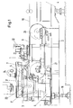
- Fig. 1 shows a casting device for the continuous production of metal strip 19, consisting of the endless cooling belt 9, which is guided over transport rollers 20, 21 and driven in rotation.
- a cooling or smoothing roller 1 is arranged above the cooling belt 9 and its position relative to the cooling belt 9 can be changed by actuating cylinders 22.
- the cooling belt 9 including the transport rollers 20, 21 is mounted on a frame 2 which is adjustable in the inclination to the horizontal.
- the frame 2 is articulated on one side, with an articulated axis 4, which extends transversely to the tape take-off direction and rests on the opposite side on vertically arranged hydraulically operated actuating cylinders 16.
- a gas source is designated, which is connected to the outlet chamber 3 ⁇ .
- the distribution vessel 3 is also adjustable in position.
- the distributor vessel 3 consists of an inlet chamber 3 'and an outlet chamber 3 ⁇ . At the outlet chamber 3 ⁇ , the pouring nozzle 7 is arranged.
- the pouring chamber 3 is sealed gas-tight above the melt.
- the distributor 3, which is designed as a double-chamber vessel, is separated into the areas of the pouring chamber 3 'and the pouring chamber 3' by a central wall 23 which projects from above into the distributor and into the melt.
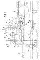
- the movable carriage 6 carrying the distributor 3 is mounted on the frame 2.
- the distributor 3 can be adjusted in height by means of a hydraulic cylinder 13.
- the hydraulic cylinder 13 is included in a control circuit which includes the regulator R1 and a dynamic pressure measurement of a gas jet emerging at the casting nozzle 7, as shown in more detail in FIG. 3.
- the distance measuring device 11 with the measuring opening 11 ' is arranged on or in the wall of the casting nozzle 7 assigned to the belt inlet side.
- the dynamic pressure of the gas emerging at 11 'as a measure of the distance of the pouring nozzle 7 from the cooling belt 9 is fed to the controller R1.
- the controller R1 controls the hydraulic cylinder 13 in the sense of keeping the distance of the pouring nozzle 7 from the surface of the cooling belt 9 constant.
- the pouring nozzle 7 is immediately downstream of a thickness measuring device 14 in the direction of strip travel for determining the thickness of the metal strip 19 produced.
- the thickness measuring device works according to the radiographic method and accordingly has transmitters and receivers which are arranged above or below the strip.
- the measuring device 14 is connected to the pressure-controllable gas source 24 via the regulator R2.
- the bath level of the melt 25 can be regulated via the gas pressure in the pouring chamber 3 ⁇ and thus the amount of outflow from the pouring nozzle 7 leaking metal.
- the “gas source” is operated as a connection to a vacuum chamber.
- the measuring device 14 is also connected to a further controller R4, which carries adjusting means for influencing the distance from the support elements 18 arranged below the cooling belt 9.
- the support elements 18 in the form of a continuous roll or a roll consisting of individual sections are arranged in the region of the outlet opening of the pouring nozzle 7.
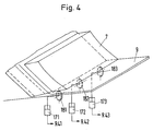
- the controllable position of the support elements 18 also makes it possible to influence the thickness of the band 19 to be produced. In the event that the support element 18 consists of several individual rollers, a corresponding number of adjusting elements 15 are of course required.
- FIG. 4. 4 shows the pouring nozzle 7 with individual rollers 181, 182, 183 arranged below the belt 9.
- Each roller is assigned a corresponding actuating means 171, 172, 173, each of which is connected to its own controller R41, R42, R43.
- R41, R42, R43 Such a breakdown of the support elements naturally makes it necessary for a corresponding number of thickness measuring devices 14 to also be present, so that each thickness measuring device 14 is assigned a corresponding supporting roller. This division makes it possible to achieve a finer adjustment and influencing of the strip thickness over the strip width.
- FIG. 2 which detects the belt speed of the cooling belt 9, feeds the belt speed to a controller R3 and acts on an actuating cylinder 16, with the aid of which the inclination of the casting belt can be regulated as a function of the belt speed.
Abstract
Description
Die vorliegende Erfindung betrifft eine Vorrichtung und ein Verfahren zum Gießen von Bändern aus Metall, insbesondere aus Stahl, bei dem die Metallschmelze aus einer vorzugsweise der Bandbreite entsprechenden Ausgießdüse auf ein kontinuierlich bewegtes, gekühltes Transportband aufgegeben wird und der Düsenmund mit seiner Ebene auf die Dicke des zu gießenden Metallbandes, d.h. auf einen spitzen Winkel zur Transportbandebene einstellbar ist. Eine derartige Vorrichtung gehört gemäß der älteren Patentanmeldung P 37 07 897.6 zum Stand der Technik.The present invention relates to an apparatus and a method for casting strips of metal, in particular steel, in which the molten metal is fed from a pouring nozzle, which preferably corresponds to the strip width, onto a continuously moving, cooled conveyor belt and the nozzle mouth with its plane to the thickness of the metal strip to be cast, ie is adjustable to an acute angle to the conveyor belt level. Such a device belongs to the prior art according to the earlier patent application P 37 07 897.6.
Die vorliegende Erfindung hat sich die Aufgabe gestellt, die mit einer derartigen Anlage herstellbaren dünnen Stahlbänder qualitätsmäßig und die Anlage hinsichtlich der Handhabbarkeit und der Betriebssicherheit zu verbessern.The object of the present invention is to improve the quality of the thin steel strips that can be produced with such a system and to improve the system in terms of manageability and operational safety.
In bezug auf die Gießeinrichtung zur kontinuierlichen Herstellung von Metallband, mit einem umlaufenden Kühlband und einem Verteiler mit Gießdüse, wobei das Kühlband auf einem in der Neigung zur Horizontalen verstellbaren Rahmen gelagert und der Verteiler innerhalb des Rahmens höhenverstellbar ist, wird daher erfindungsgemäß vorgeschlagen, daß der Verteiler als Doppelkammergefäß ausgebildet, zumindest die mit der Gießdüse versehene Ausgießkammer oberhalb der Schmelze gasdicht geschlossen und mit einer druckregelbaren Gasquelle verbunden ist, daß ferner der Gießdüse eine lagenveränderbare, anstellbare Glättrolle nachgeordnet ist, an der Gießdüse wenigstens ein Abstandsmeßgerät zur Feststellung der Lage der Gießdüse zum Kühlband vorgesehen und über einen Regler mit Mitteln zur Lageänderung des Verteilers verbunden ist.With regard to the casting device for the continuous production of metal strip, with a circumferential cooling belt and a distributor with a pouring nozzle, the cooling belt being mounted on a frame which is adjustable in inclination to the horizontal and the distributor being adjustable in height within the frame, the invention therefore proposes that the Distributor designed as a double chamber vessel, at least the pouring chamber provided with the pouring nozzle is sealed gas-tight above the melt and is connected to a pressure-controllable gas source, that the pouring nozzle is followed by a position-adjustable, adjustable smoothing roller, at least one distance measuring device on the pouring nozzle for determining the position of the pouring nozzle Cooling belt is provided and is connected via a controller with means for changing the position of the distributor.
Eine weitere erfindungsgemäße Ausgestaltung der Gießeinrichtung sieht vor, daß das Abstandsmeßgerät ein Staudruckmeßgerät ist und die Meßöffnung in der Ebene der Austrittsöffnung der Gießdüse in der Wand der Gießdüse angeordnet ist, die der Bandeinlaufseite zugeordnet ist und die Austrittsöffnung der Gießdüse zur Oberfläche des Kühlbandes geneigt angeordnet ist und der Neigungswinkel sich in Bandabzugsrichtung öffnet.Another embodiment of the casting device according to the invention provides that the distance measuring device is a dynamic pressure measuring device and the measuring opening is arranged in the plane of the outlet opening of the casting nozzle in the wall of the casting nozzle which is assigned to the strip inlet side and which Outlet opening of the pouring nozzle is arranged inclined to the surface of the cooling belt and the angle of inclination opens in the direction of strip withdrawal.
In weiterer Ausgestaltung der Erfindung ist vorgesehen, daß in Bandabzugsrichtung hinter der Gießdüse Mittel angeordnet sind, mit denen die Dicke des gegossenen Bandes erfaßt werden kann und daß die gemessenen Werte in einer Regeleinheit mit vorgegebenen Sollwerten verglichen werden und der Regler auf die Gasquelle im Sinne einer Druckänderung einwirkt, um über eine Steuerung der Schmelzenausflußmenge die vorgesehene Banddicke zu regulieren.In a further embodiment of the invention it is provided that means are arranged in the strip take-off direction behind the casting nozzle, with which the thickness of the cast strip can be detected and that the measured values are compared in a control unit with predetermined target values and the regulator on the gas source in the sense of a Pressure change acts to regulate the intended strip thickness by controlling the melt flow rate.
Das Mittel zur Feststellung der Banddicke ist insbesondere ein radiometrisch arbeitendes Meßgerät. In einer Abwandlung des erfindungsgemäßen Verfahrens kann das radiometrisch arbeitende Meßgerät mit einem weiteren Regler verbunden sein, der mit Stellantrieben von einem unterhalb des Kühlbandes angeordneten, höhenverstellbaren Stützelement verbunden ist. Dieses Stützelement liegt insbesondere unterhalb der Gießdüse und kann mit zur Steuerung der Banddicke herangezogen werden.The means for determining the strip thickness is in particular a radiometric measuring device. In a modification of the method according to the invention, the radiometric measuring device can be connected to a further controller, which is connected to actuators by a height-adjustable support element arranged below the cooling belt. This support element is in particular below the pouring nozzle and can also be used to control the strip thickness.
In weiterer Ausgestaltung der Erfindung wird vorgeschlagen, daß über die Bandbreite verteilt mehrere Meßgeräte angeordnet sind, wobei jedes Meßgerät jeweils über einen Regler mit den entsprechenden Stellantrieben je eines Stützelementes verbunden ist.In a further embodiment of the invention, it is proposed that several measuring devices are arranged distributed over the bandwidth, each measuring device being connected to the corresponding actuating drives of one supporting element each via a controller.
In weiterer Ausgestaltung der Erfindung ist vorgesehen, daß für den Fall, daß die Gießdüse in der Breitenerstreckung der Breite des zu gießenden Bandes entspricht, die eingangs erwähnten Abstandsmeßgeräte in den Außenbereich der Gießdüse angeordnet sind, um ein Verkippen des Bandes gegenüber des Gießdüse zu vermeiden und um ein über die gesamte Breite gleichmäßiges dickes Band zu erzeugen.In a further embodiment of the invention it is provided that in the event that the pouring nozzle corresponds in width to the width of the strip to be cast, the distance measuring devices mentioned at the outset are arranged in the outer region of the pouring nozzle in order to prevent the strip from tilting relative to the pouring nozzle and to create a thick band that is uniform across the entire width.
Bezüglich des Verfahrens zum Betrieb einer Gießvorrichtung zur kontinuierlichen Herstellung von Metallband, bei dem Schmelze aus einem Verteiler in eine Gießform, die aus einem umlaufenden Kühlband, einer Gießdüse und dem Kühlband zugeordneter Kühlrolle besteht, zugeführt wird, wobei die Lage der Austrittsöffnung der Gießdüse zum Kühlband die Dicke des des erzeugten Bandes bestimmt, wird erfindungsgemäß vorgeschlagen, daß die daß die Dicke des gegossenen Bandes gemessen, der Meßwert einem Regeler zugeführt wird und nach Vergleich mit einem vorgegebenen, die Dicke des Bandes charakterisierenden Sollwert der Gasdruck in der Ausgießkammer des Verteilergefäßes in Verbindung mit der Zulaufmenge der Schmelze in die Eingießkammer geregelt wird.Regarding the method for operating a casting device for the continuous production of metal strip, in which melt is fed from a distributor into a casting mold, which consists of a rotating cooling belt, a casting nozzle and the cooling belt assigned cooling roller, the position of the outlet opening of the casting nozzle relative to the cooling belt determines the thickness of the strip produced, it is proposed according to the invention that the thickness of the cast strip is measured, the measured value is fed to a regulator and, after comparison with a predetermined setpoint characterizing the thickness of the strip, the gas pressure in the pouring chamber of the distributor vessel in connection is regulated with the flow rate of the melt into the pouring chamber.
Das vorbeschriebene Verfahren zum Betrieb einer Gießeinrichtung kann in weiterer Ausgestaltung der Erfindung, ausgehend von der zuvor beschriebenen gattungsgemäßen Art dadurch gekennzeichnet sein, daß der Abstand der Gießdüse mittels Staudruckmessung eines aus einer Meßöffnung in der Ebene in der Austrittsöffnung austretenden Gasstrahles erfaßt, ein dem Meßwert des Staudruckes entsprechendes Signal einem Regler zugeführt wird und nach Vergleich mit einem Sollwert, der den Abstand der Düse vom Kühlband charakterisiert, an den Verteiler angreifende Stellmittel in Sinne einer Konstanthaltung des Meßwertes bzw. des Abstandes Gießdüse zur Kühlbandoberfläche betätigt wird.The above-described method for operating a pouring device can be characterized in a further embodiment of the invention, starting from the previously described generic type, in that the distance of the pouring nozzle is measured by means of a dynamic pressure measurement of a gas jet emerging from a measuring opening in the plane in the outlet opening, a the measured value of Signal corresponding to the dynamic pressure is fed to a controller and, after comparison with a target value which characterizes the distance of the nozzle from the cooling belt, actuating means acting on the distributor are actuated in the sense of keeping the measured value constant or the distance between the casting nozzle and the cooling belt surface.
Es gehört mit zur verfahrenstechnischen Ausgestaltung der Erfindung, daß die Dicke des gegossenen Bandes mittels mehrerer Dickenmeßgeräte in der Nähe der Gießdüse verteilt über die Bandbreite gemessen wird, die Meßwerte der einzelnen Meßgeräte mit einer vorgegebenen, die Dicke des Bandes charakterisierenden Sollwertes in einem je einem Meßgerät zugeordneten Regler verglichen und bei Abweichungen vom Sollwert dem Stellantrieb des jeweils dem Dickenmeßgerät zugeordneten, der Gießdüse gegenüberliegenden Stützelement zur Einstellung eines gewünschten Profils zugeführt und eingestellt wird.It is part of the procedural embodiment of the invention that the thickness of the cast strip is measured by means of several thickness gauges in the vicinity of the pouring nozzle distributed over the bandwidth, the measured values of the individual measuring instruments with a predetermined setpoint characterizing the thickness of the strip in one measuring device each assigned controller and, in the event of deviations from the setpoint, supplied to the actuator of the respective support element assigned to the thickness measuring device and opposite the casting nozzle for setting a desired profile and is set.
Die Erfindung soll anhand der beiliegenden Zeichnungen näher erläutert werden.The invention will be explained in more detail with reference to the accompanying drawings.
Es zeigen
- Fig. 1 eine Seitenansicht der Gießeinrichtung,
- Fig. 2 eine Seitenansicht der Gießeinrichtung mit den erfindungsgemäßen Regelkreisen,
- Fig. 3 die Anordnung des Staudruckmeßgerätes an der Gießdüse und
- Fig. 4 die Anordnung von Stützelementen für das Kühlband unter der Gießdüse.
- 1 is a side view of the pouring device,
- 2 is a side view of the casting device with the control circuits according to the invention,
- Fig. 3 shows the arrangement of the dynamic pressure gauge on the pouring nozzle and
- Fig. 4 shows the arrangement of support elements for the cooling belt under the pouring nozzle.
In der Zeichnung sind gleiche Teile mit den gleichen Bezugszeichen versehen.In the drawing, the same parts are provided with the same reference symbols.
Fig. 1 zeigt eine Gießeinrichtung zum kontinuierlichen Herstellen von Metallband 19, bestehend aus dem endlosen Kühlband 9, das über Transportrollen 20, 21 geführt und umlaufend angetrieben wird. Oberhalb des Kühlbandes 9 ist eine Kühl- bzw. Glättrolle 1 angeordnet, die durch Stellzylinder 22 in ihrer Lage zum Kühlband 9 veränderbar ist. Das Kühlband 9 einschließlich der Transportrollen 20, 21 ist auf einem Rahmen 2 gelagert, der in der Neigung zur Horizontalen verstellbar ist. Zu diesem Zweck ist der Rahmen 2 an einer Seite gelenkig gelagert, mit einer Gelenkachse 4, die sich quer zur Bandabzugsrichtung erstreckt und an der gegenüberliegenden Seite auf vertikal angeordneten hydraulisch betriebenen Stellzylindern 16 ruht. Mit 24 ist eine Gasquelle bezeichnet, die an die Auslaufkammer 3˝ angeschlossen ist.Fig. 1 shows a casting device for the continuous production of
Innerhalb des Rahmens 2 ist das Verteilergefäß 3 ebenfalls in der Lage verstellbar gelagert. Das Verteilergefäß 3 besteht aus einer Einlaufkammer 3′ und aus einer Auslaufkammer 3˝. An der Auslaufkammer 3˝ ist die Gießdüse 7 angeordnet. Die Ausgießkammer 3 ist oberhalb des Schmelze gasdicht verschlossen. Der als Doppelkammergefäß ausgebildete Verteiler 3 wird in die Bereiche Eingießkammer 3′ und Ausgießkammer 3˝ durch eine Mittenwand 23 getrennt, die von oben in den Verteiler bis in die Schmelze hineinragt.Within the
Gemäß Fig. 2 ist der den Verteiler 3 tragende, verfahrbare Wagen 6 auf dem Rahmen 2 gelagert. Der Verteiler 3 ist mittels Hydraulikzylinder 13 höhenverstellbar. Der Hydraulikzylinder 13 ist in einen Regelkreis einbezogen, der den Regler R1 und eine Staudruckmessung eines an der Gießdüse 7 austretenden Gasstrahles umfaßt, wie in Fig. 3 näher dargestellt. Hier ist in der Ebene der Düsenaustrittsöffnung 8, die einen Neigungswinkel 10 zum Kühlband 9 einschließt, das Abstandsmeßgerät 11 mit der Meßöffnung 11′ an bzw. in der der Bandeinlaufseite zugeordneten Wand der Gießdüse 7 angeordnet. Der Staudruck des bei 11′ austretenden Gases als Maß für den Abstand der Gießdüse 7 vom Kühlband 9 wird dem Regler R1 zugeführt. Der Regler R1 steuert den Hydraulikzylinder 13 im Sinne einer Konstanthaltung des Abstandes der Gießdüse 7 von der Oberfläche des Kühlbandes 9.2, the
Weiter ist in Fig. 2 der Gießdüse 7 in Bandlaufrichtung unmittelbar nachgeordnet ein Dickenmeßgerät 14 zur Feststellung der Dicke des erzeugten Metallbandes 19. Das Dickenmaßgerät arbeitet nach der Durchstrahlungsmethode und weist demgemäß Sender und Empfänger auf, die über bzw. unter dem Band angeordnet sind. Das Meßgerät 14 ist über den Regler R2 mit der drucksteuerbaren Gasquelle 24 verbunden. Über den Gasdruck in der Ausgießkammer 3˝ kann der Badspiegelstand der Schmelze 25 geregelt werden und damit die Ausflußmenge des aus der Gießdüse 7 austretenden Metalles. In Abhängigkeit von der Geometrie des Verteilers 3, also der Ausbildung als Doppelkammer der Lage der Gießdüse 7 und der Lage der Unterkante der Mittenwand 23, wird die "Gasquelle" als Anschluß an eine Unterdruckkammer betrieben. Dadurch ist es möglich, in Abstimmung mit der in die Eingießkammer fließenden Schmelzenmenge den Höhenstand der Schmelze so zu regulieren, daß für den Schmelzenfluß in der Gießdüse nur der in der Eingießkammer vorhandene ferrostatische Druck maßgeblich wirkt. Das Meßgerät 14 steht ferner mit einem weiteren Regler R4 in Verbindung, der Stellmittel zur Beeinflussung des Abstandes von unterhalb des Kühlbandes 9 angeordneten Stützelementen 18 trägt. Die Stützelemente 18 in Form einer durchgehenden oder auch aus einzelnen Abschnitten bestehenden Rolle sind im Bereich der Austrittsöffnung der Gießdüse 7 angeordnet. Durch die steuerbare Lage der Stützelemente 18 ist ebenfalls eine Beeinflussung der Dicke des zu erzeugenden Bandes 19 möglich. Für den Fall, daß das Stützelement 18 aus mehreren Einzelrollen besteht, sind natürlich eine entsprechende Anzahl von Stellelementen 15 erforderlich. Diese Einzelheit ist in Fig. 4 dargestellt. Fig. 4 zeigt die Gießdüse 7 mit unterhalb des Bandes 9 angeordneten Einzelrollen 181, 182, 183. Dabei ist jeder Rolle ein entsprechendes Stellmittel 171, 172, 173 zugeordnet, die jeweils mit einem eigenen Regler R41, R42, R43 verbunden sind. Eine derartige Aufgliederung der Stützelemente macht es natürlich erforderlich, daß auch eine entsprechende Anzahl von Dickenmeßgeräten 14 vorhanden ist, so daß jedem Dickenmeßgerät 14 eine entsprechende Stützrolle zugeordnet ist. Durch diese Aufteilung ist es möglich, eine feinere Einstellung und Beeinflussung der Banddicke über die Bandbreite zu erzielen.Furthermore, in FIG. 2, the
Desweiteren ist in Fig. 2 ein zusätzlicher Regelkreis dargestellt, der die Bandgeschwindigkeit des Kühlbandes 9 erfaßt, die Bandgeschwindigkeit einem Regler R3 zuführt und auf einen Stellzylinder 16 wirkt, mit dessen Hilfe die Neigung des Gießbandes in Abhängigkeit von der Bandgeschwindigkeit geregelt werden kann.Furthermore, an additional control circuit is shown in FIG. 2, which detects the belt speed of the
Claims (10)
dadurch gekennzeichnet,
daß die gasdicht verschlossene Kammer mit einer druckregelbaren Gasquelle (24) verbunden ist und an der Gießdüse (7) wenigstens ein Abstandsmeßgerät (11) zur Feststellung der Lage der Gießdüse (7) zum Kühlband (9) vorgesehen und über einen Regler (R1) mit Mitteln (13) zur Lageänderung des Verteilers (3) verbunden ist.1. Casting device for the continuous production of metal strip, with a circumferential cooling belt, a distributor with a pouring nozzle and a positionable adjustable smoothing roll arranged downstream of the pouring nozzle, the cooling belt being mounted on a frame that is adjustable in inclination to the horizontal and the distributor is height-adjustable within the frame, the distributor (3) designed as a double chamber vessel with a pouring chamber (3 ') and a pouring chamber (3˝) and at least the pouring chamber (3˝) provided with the pouring nozzle (7) is closed gas-tight above the melt,
characterized,
that the gas-tight chamber is connected to a pressure-controllable gas source (24) and at least one distance measuring device (11) is provided on the casting nozzle (7) for determining the position of the casting nozzle (7) in relation to the cooling belt (9) and via a controller (R1) Means (13) for changing the position of the distributor (3) is connected.
dadurch gekennzeichnet,
daß das Abstandsmeßgerät (11) ein Staudruckmeßgerät ist und die Meßöffnung (11′) in der Ebene der Austrittsöffnung (8) der Gießdüse (7) in der Wand der Gießdüse (7) angeordnet ist, die der Bandeinlaufseite zugeordnet ist und die Austrittsöffnung (8) der Gießdüse (7) zur Oberfläche des Kühlbandes (9) geneigt angeordnet ist und der Neigungswinkel (10) sich in Bandabzugsrichtung öffnet.2. Pouring device according to claim 1,
characterized,
that the distance measuring device (11) is a dynamic pressure measuring device and the measuring opening (11 ') is arranged in the plane of the outlet opening (8) of the pouring nozzle (7) in the wall of the pouring nozzle (7) which is assigned to the strip inlet side and the outlet opening (8 ) the pouring nozzle (7) is arranged inclined to the surface of the cooling belt (9) and the angle of inclination (10) opens in the direction of strip withdrawal.
dadurch gekennzeichnet,
daß die druckregelbare Gasquelle (24) über einen Regler (R2) mit in Bandabzugsrichtung der Gießdüse (7) nachgeordneten Mitteln (14) zur Feststellung der Dicke des gegossenen Bandes (19) versehen ist.3. Pouring device according to claim 1,
characterized,
that the pressure-controllable gas source (24) is provided via a controller (R2) with means (14) downstream in the strip take-off direction of the casting nozzle (7) for determining the thickness of the cast strip (19).
dadurch gekennzeichnet,
daß das Mittel (14) ein radiometrisch arbeitendes Meßgerät ist.4. Pouring device according to claim 3,
characterized,
that the means (14) is a radiometric measuring device.
dadurch gekennzeichnet,
daß das radiometrisch arbeitende Meßgerät (14) mit einem Regler (R4) verbunden und der Regler (R4) mit einem Stellantriebe (17) von einem unterhalb des Kühlbandes (9) angeordneten, der Gießdüse (7) gegenüberliegenden, höhenverstellbaren Stützelement (18) verbunden ist.5. Pouring device according to one of claims 1 to 4,
characterized,
that the radiometric measuring device (14) is connected to a controller (R4) and the controller (R4) is connected to an actuator (17) by a height-adjustable support element (18) arranged below the cooling belt (9) and opposite the pouring nozzle (7) is.
dadurch gekennzeichnet,
daß über die Bandbreite verteilt mehrere Meßgeräte (14) angeordnet sind, wobei jedes Meßgerät jeweils über einen Regler (R41, R42, R43) mit den entsprechenden Stellantrieben (171, 172, 173) je eines Stützelementes (181, 182, 183) verbunden ist.6. Pouring device according to claim 5,
characterized,
that several measuring devices (14) are arranged distributed over the bandwidth, each measuring device being connected via a controller (R41, R42, R43) to the corresponding actuators (171, 172, 173) each of a supporting element (181, 182, 183) .
dadurch gekennzeichnet,
daß die Gießdüse (7) der Breite des zu gießenden Bandes (19) entspricht und in den Außenbereichen der Gießdüse (7) Abstandsmeßgeräte (11) angeordnet sind.7. Pouring device according to claims 1 and 2,
characterized,
that the pouring nozzle (7) corresponds to the width of the strip (19) to be poured and distance measuring devices (11) are arranged in the outer regions of the pouring nozzle (7).
dadurch gekennzeichnet,
daß die Dicke des gegossenen Bandes gemessen, der Meßwert einem Regeler zugeführt wird und nach Vergleich mit einem vorgegebenen, die Dicke des Bandes charakterisierenden Sollwert der Gasdruck in der Ausgießkammer (3˝) des Verteilergefäßes (3) in Verbindung mit der Zulaufmenge der Schmelze in die Eingießkammer (3′) geregelt wird.8. A method for operating a casting device for the continuous production of metal strip, in which melt is fed from a distributor into a casting mold, which consists of a rotating cooling belt, a casting nozzle and the cooling belt associated cooling roller, the ferrostatic pressure in the distributor and the size the outlet cross-section of the casting nozzle in conjunction with the position of the outlet opening of the casting nozzle relative to the cooling belt determines the thickness of the belt produced,
characterized,
that the thickness of the cast strip is measured, the measured value is fed to a regulator and, after comparison with a predetermined setpoint characterizing the thickness of the strip, the gas pressure in the pouring chamber (3˝) of the distributor vessel (3) in connection with the feed quantity of the melt into the Pouring chamber (3 ') is regulated.
dadurch gekennzeichnet,
daß der Abstand der Gießdüse (7) mittels Staudruckmessung eines aus einer Öffnung in der Ebene der Austrittsöffnung (8) austretenden Gasstrahles erfaßt, daß ein den Meßwert des Staudruckes entsprechendes Signal einem Regler zugeführt wird und nach Vergleich mit einem Sollwert, der den Abstand der Düse (7) vom Kühlband (9) charakterisiert, an den Verteiler (3) angreifende Stellmittel (13) im Sinne einer Konstanthaltung des Meßwertes bzw. des Abstandes der Gießdüse (7) zur Kühlbandoberfläche betätigt werden.9. A method for operating a casting device for the continuous production of metal strip, in which melt is fed from a distributor into a casting mold, which consists of a rotating cooling belt, a casting nozzle and the cooling belt assigned cooling roller, the ferrostatic pressure in the distributor and the size the outlet cross-section of the casting nozzle in conjunction with the position of the outlet opening of the casting nozzle relative to the cooling belt determines the thickness of the belt produced,
characterized,
that the distance of the pouring nozzle (7) by means of a dynamic pressure measurement of a gas jet emerging from an opening in the plane of the outlet opening (8) detects that a signal corresponding to the measured value of the dynamic pressure is fed to a controller and after comparison with a setpoint value which measures the distance of the nozzle (7) characterized by the cooling belt (9), actuating means (13) acting on the distributor (3) are actuated in the sense of keeping the measured value constant or the distance of the pouring nozzle (7) from the cooling belt surface.
dadurch gekennzeichnet,
daß die Dicke des gegossenen Bandes mittels mehrerer Dickenmeßgeräte in der Nähe der Gießdüse verteilt über die Bandbreite gemessen wird, die Meßwerte der einzelnen Meßgeräte mit einer vorgegebenen, die Dicke des Bandes charakterisierenden Sollwertes in einem je einem Meßgerät zugeordneten Regler verglichen und bei Abweichungen vom Sollwert dem Stellantrieb des jeweils dem Dickenmeßgerät zugeordneten, der Gießdüse gegenüberliegenden Stützelement zur Einstellung eines gewünschten Profils zugeführt und eingestellt wird.10. A method of operating a casting device for the continuous production of metal strip, in which melt is fed from a distributor into a casting mold, which consists of a rotating cooling belt, a casting nozzle and the cooling belt assigned cooling roller, the ferrostatic pressure in the distributor and the size the outlet cross-section of the casting nozzle in conjunction with the position of the outlet opening of the casting nozzle relative to the cooling belt determines the thickness of the belt produced,
characterized,
that the thickness of the cast strip is measured by means of several thickness gauges in the vicinity of the pouring nozzle distributed over the strip width, the measured values of the individual gauges with a predetermined desired value characterizing the thickness of the strip in a respective measuring device assigned controller and, in the event of deviations from the target value, the actuator of the respective support element assigned to the thickness measuring device and opposite the casting nozzle is fed and adjusted to set a desired profile.
Priority Applications (1)
| Application Number | Priority Date | Filing Date | Title |
|---|---|---|---|
| AT89730066T ATE89770T1 (en) | 1988-03-24 | 1989-03-14 | CASTING EQUIPMENT FOR THE CONTINUOUS PRODUCTION OF METAL STRIP AND PROCESS. |
Applications Claiming Priority (2)
| Application Number | Priority Date | Filing Date | Title |
|---|---|---|---|
| DE3810302 | 1988-03-24 | ||
| DE3810302A DE3810302A1 (en) | 1988-03-24 | 1988-03-24 | CASTING DEVICE FOR THE CONTINUOUS PRODUCTION OF METAL STRIP |
Publications (3)
| Publication Number | Publication Date |
|---|---|
| EP0334802A2 true EP0334802A2 (en) | 1989-09-27 |
| EP0334802A3 EP0334802A3 (en) | 1990-11-22 |
| EP0334802B1 EP0334802B1 (en) | 1993-05-26 |
Family
ID=6350766
Family Applications (1)
| Application Number | Title | Priority Date | Filing Date |
|---|---|---|---|
| EP89730066A Expired - Lifetime EP0334802B1 (en) | 1988-03-24 | 1989-03-14 | Casting equipment for continuous producing metal strips and method |
Country Status (10)
| Country | Link |
|---|---|
| US (1) | US5000250A (en) |
| EP (1) | EP0334802B1 (en) |
| JP (1) | JP2925568B2 (en) |
| KR (1) | KR960007493B1 (en) |
| AT (1) | ATE89770T1 (en) |
| BR (1) | BR8901364A (en) |
| DE (2) | DE3810302A1 (en) |
| DK (1) | DK137189A (en) |
| ES (1) | ES2040497T3 (en) |
| ZA (1) | ZA892180B (en) |
Cited By (8)
| Publication number | Priority date | Publication date | Assignee | Title |
|---|---|---|---|---|
| EP0463256A2 (en) * | 1990-06-22 | 1992-01-02 | Armco Inc. | Electronic gap sensor and method |
| EP0463255A2 (en) * | 1990-06-22 | 1992-01-02 | Armco Inc. | Pneumatic gap sensor and method |
| EP0534174A1 (en) * | 1991-09-27 | 1993-03-31 | Wieland-Werke Ag | Process and device for fabricating a near net shape metal strip |
| WO1994008742A1 (en) * | 1992-10-10 | 1994-04-28 | Sundwiger Eisenhütte Maschinenfabrik Gmbh & Co. | Strip casting machine consisting of at least one moving cooling surface, especially a foundry wheel with upstream casting nozzle or tundish |
| EP0613744A1 (en) * | 1993-03-05 | 1994-09-07 | Wieland-Werke Ag | Casting equipment for continuously producing metal strips |
| US5538071A (en) * | 1991-07-01 | 1996-07-23 | Mannesmann Aktiengesellschaft | Machine and method of continuously casting a metal strip |
| WO2008110330A1 (en) * | 2007-03-09 | 2008-09-18 | Sms Siemag Ag | Device for thickness measurement and method therefor |
| WO2012080191A1 (en) * | 2010-12-15 | 2012-06-21 | Sms Siemag Ag | Device and method for the horizontal casting of metal strips |
Families Citing this family (11)
| Publication number | Priority date | Publication date | Assignee | Title |
|---|---|---|---|---|
| US5092392A (en) * | 1990-06-22 | 1992-03-03 | Armco, Inc. | Pneumatic gap sensor and method |
| DE4039959C1 (en) * | 1990-12-14 | 1992-01-23 | Wieland-Werke Ag, 7900 Ulm, De | |
| DE4132189C1 (en) * | 1991-09-27 | 1993-02-04 | Wieland-Werke Ag, 7900 Ulm, De | Metal strip prodn. - by feeding molten metal from tundish via casting nozzle onto cooled conveyor belt |
| DE4344953C2 (en) * | 1993-12-27 | 1996-10-02 | Mannesmann Ag | Method and device for casting a metal strip close to its final dimensions |
| DE4407873C2 (en) * | 1994-03-04 | 1997-04-10 | Mannesmann Ag | Method and device for cooling molten steel |
| US6026887A (en) * | 1997-03-04 | 2000-02-22 | Hazelett Strip-Casting Corporation | Steering, tensing and driving a revolving casting belt using an exit-pulley drum for achieving all three functions |
| DE19811434C2 (en) * | 1998-03-17 | 2002-05-16 | Mannesmann Ag | Method and device for uniformizing a molten metal film |
| DE50301315D1 (en) * | 2003-08-01 | 2006-02-16 | Hof Te Fiennes N V | Casting system and method for casting non-ferrous molten metals |
| DE102008005727B3 (en) * | 2008-01-23 | 2009-10-01 | Technische Universität Clausthal | Feeding device for a molten metal and a belt casting device equipped with such a device |
| CN103286291B (en) * | 2013-05-27 | 2015-04-29 | 平湖东创新材料科技有限公司 | Plate forming device |
| DE102015114725B3 (en) * | 2015-09-03 | 2016-12-08 | Salzgitter Flachstahl Gmbh | Melt feed system for a horizontal strip caster |
Citations (5)
| Publication number | Priority date | Publication date | Assignee | Title |
|---|---|---|---|---|
| JPS5841654A (en) * | 1981-09-02 | 1983-03-10 | Hitachi Metals Ltd | Producing device for thin alloy sheet |
| GB2140720A (en) * | 1983-06-01 | 1984-12-05 | Alusuisse | Feeding molten metal through a nozzle to a casting mould |
| JPS6021158A (en) * | 1983-07-15 | 1985-02-02 | Nisshin Steel Co Ltd | Continuous casting device for thin plate |
| JPS61137658A (en) * | 1984-12-10 | 1986-06-25 | Kawasaki Steel Corp | Method for estimating thickness of quickly cooled thin strip |
| DE3707897A1 (en) * | 1987-03-12 | 1988-09-22 | Mannesmann Ag | METHOD AND CASTING DEVICE FOR CASTING METAL STRIPS, ESPECIALLY STEEL |
Family Cites Families (8)
| Publication number | Priority date | Publication date | Assignee | Title |
|---|---|---|---|---|
| US4449568A (en) * | 1980-02-28 | 1984-05-22 | Allied Corporation | Continuous casting controller |
| JPS57142748A (en) * | 1981-02-27 | 1982-09-03 | Hitachi Ltd | Molding device for thin plate |
| JPS59150646A (en) * | 1983-02-17 | 1984-08-28 | Kawasaki Steel Corp | Method and device for continuous casting of metallic plate |
| CH661882A5 (en) * | 1983-06-01 | 1987-08-31 | Lauener W F Ag | METHOD FOR FEEDING A METAL MELT INTO THE CASTING SPLIT OF A CASTING MACHINE, AND CASTING MACHINE FOR CARRYING OUT THE METHOD. |
| DE3403152C2 (en) * | 1984-01-31 | 1986-02-20 | Fried. Krupp Gmbh, 4300 Essen | Method for feeding molten steel from an intermediate container into a double-band continuous casting mold and intermediate container for carrying out the method |
| DE3440237C2 (en) * | 1984-11-03 | 1986-11-06 | Mannesmann AG, 4000 Düsseldorf | Device for continuous strip casting of metals, in particular steel |
| JPS61144251A (en) * | 1984-12-18 | 1986-07-01 | Kawasaki Heavy Ind Ltd | Method and device for exchanging nozzle of continuous casting installation |
| US4646812A (en) | 1985-09-20 | 1987-03-03 | Battelle Development Corporation | Flow casting |
-
1988
- 1988-03-24 DE DE3810302A patent/DE3810302A1/en active Granted
-
1989
- 1989-03-14 AT AT89730066T patent/ATE89770T1/en not_active IP Right Cessation
- 1989-03-14 EP EP89730066A patent/EP0334802B1/en not_active Expired - Lifetime
- 1989-03-14 DE DE8989730066T patent/DE58904455D1/en not_active Expired - Lifetime
- 1989-03-14 ES ES198989730066T patent/ES2040497T3/en not_active Expired - Lifetime
- 1989-03-21 DK DK137189A patent/DK137189A/en not_active Application Discontinuation
- 1989-03-22 JP JP1070328A patent/JP2925568B2/en not_active Expired - Lifetime
- 1989-03-22 ZA ZA892180A patent/ZA892180B/en unknown
- 1989-03-22 BR BR898901364A patent/BR8901364A/en not_active IP Right Cessation
- 1989-03-23 KR KR1019890003653A patent/KR960007493B1/en not_active IP Right Cessation
- 1989-03-24 US US07/328,161 patent/US5000250A/en not_active Expired - Lifetime
Patent Citations (5)
| Publication number | Priority date | Publication date | Assignee | Title |
|---|---|---|---|---|
| JPS5841654A (en) * | 1981-09-02 | 1983-03-10 | Hitachi Metals Ltd | Producing device for thin alloy sheet |
| GB2140720A (en) * | 1983-06-01 | 1984-12-05 | Alusuisse | Feeding molten metal through a nozzle to a casting mould |
| JPS6021158A (en) * | 1983-07-15 | 1985-02-02 | Nisshin Steel Co Ltd | Continuous casting device for thin plate |
| JPS61137658A (en) * | 1984-12-10 | 1986-06-25 | Kawasaki Steel Corp | Method for estimating thickness of quickly cooled thin strip |
| DE3707897A1 (en) * | 1987-03-12 | 1988-09-22 | Mannesmann Ag | METHOD AND CASTING DEVICE FOR CASTING METAL STRIPS, ESPECIALLY STEEL |
Non-Patent Citations (3)
| Title |
|---|
| PATENT ABSTRACTS OF JAPAN, vol. 10, no. 333 (M-534)(2389), 12 November 1986; & JP-A-61137658 (Kawasaki Steel) 25.06.1986 * |
| PATENT ABSTRACTS OF JAPAN, vol. 7, no. 124 (M-218)(1269), 28 May 1983; & JP-A-58 041654 (Hitachi) 10.03.1983 * |
| PATENT ABSTRACTS OF JAPAN, vol. 9, no. 142 (M-388)(1865), 18 June 1985; & JP-A-60 021158 (Nitsushin) 02.02.1985 * |
Cited By (12)
| Publication number | Priority date | Publication date | Assignee | Title |
|---|---|---|---|---|
| EP0463256A2 (en) * | 1990-06-22 | 1992-01-02 | Armco Inc. | Electronic gap sensor and method |
| EP0463255A2 (en) * | 1990-06-22 | 1992-01-02 | Armco Inc. | Pneumatic gap sensor and method |
| EP0463255A3 (en) * | 1990-06-22 | 1992-09-23 | Armco Inc. | Pneumatic gap sensor and method |
| EP0463256A3 (en) * | 1990-06-22 | 1992-10-14 | Armco Inc. | Electronic gap sensor and method |
| AU644112B2 (en) * | 1990-06-22 | 1993-12-02 | Armco Inc. | Pneumatic gap sensor and method |
| US5538071A (en) * | 1991-07-01 | 1996-07-23 | Mannesmann Aktiengesellschaft | Machine and method of continuously casting a metal strip |
| EP0534174A1 (en) * | 1991-09-27 | 1993-03-31 | Wieland-Werke Ag | Process and device for fabricating a near net shape metal strip |
| WO1994008742A1 (en) * | 1992-10-10 | 1994-04-28 | Sundwiger Eisenhütte Maschinenfabrik Gmbh & Co. | Strip casting machine consisting of at least one moving cooling surface, especially a foundry wheel with upstream casting nozzle or tundish |
| EP0613744A1 (en) * | 1993-03-05 | 1994-09-07 | Wieland-Werke Ag | Casting equipment for continuously producing metal strips |
| WO2008110330A1 (en) * | 2007-03-09 | 2008-09-18 | Sms Siemag Ag | Device for thickness measurement and method therefor |
| US9335164B2 (en) | 2007-03-09 | 2016-05-10 | Sms Group Gmbh | Device for thickness measurement and method therefor |
| WO2012080191A1 (en) * | 2010-12-15 | 2012-06-21 | Sms Siemag Ag | Device and method for the horizontal casting of metal strips |
Also Published As
| Publication number | Publication date |
|---|---|
| US5000250A (en) | 1991-03-19 |
| BR8901364A (en) | 1989-11-07 |
| DK137189A (en) | 1989-09-25 |
| EP0334802A3 (en) | 1990-11-22 |
| JPH01278946A (en) | 1989-11-09 |
| JP2925568B2 (en) | 1999-07-28 |
| DE58904455D1 (en) | 1993-07-01 |
| EP0334802B1 (en) | 1993-05-26 |
| DE3810302C2 (en) | 1990-07-05 |
| DE3810302A1 (en) | 1989-10-12 |
| KR960007493B1 (en) | 1996-06-05 |
| ZA892180B (en) | 1989-11-29 |
| DK137189D0 (en) | 1989-03-21 |
| ES2040497T3 (en) | 1993-10-16 |
| KR890014189A (en) | 1989-10-23 |
| ATE89770T1 (en) | 1993-06-15 |
Similar Documents
| Publication | Publication Date | Title |
|---|---|---|
| EP0334802B1 (en) | Casting equipment for continuous producing metal strips and method | |
| DE2757052A1 (en) | DEVICE FOR THE LEVEL MONITORING AND CONTROL OF THE MOLTEN METAL IN THE CASTING FORM OF A STRAND CASTING MACHINE | |
| DE3532763A1 (en) | Method and apparatus for the automatic pouring of molten metal | |
| EP0114293B1 (en) | Method of and installation for adjusting the taper of small face walls of continuous-casting ingots | |
| EP0019114B1 (en) | Method and apparatus for the continuous casting of several strands | |
| DE4138655C2 (en) | Outflow regulator for tundish | |
| DE4313041C2 (en) | Pouring metal tape | |
| DE3707897C2 (en) | ||
| DE2939322C2 (en) | Device for changing the distance between spray bars in a continuous caster | |
| DE3440236C2 (en) | ||
| EP4214010A1 (en) | Method and spraying apparatus for thermal surface treatment of a metal product | |
| EP0613744B1 (en) | Casting equipment for continuously producing metal strips | |
| EP1827735B1 (en) | Method and device for continuous casting of metals | |
| EP1057557B1 (en) | Process and device for continuous casting of metal | |
| EP0383413A2 (en) | Continuous-casting method | |
| DE10122118A1 (en) | Method and device for the continuous casting of blocks, slabs and thin slabs | |
| DE2830840B2 (en) | Method and device for regulating the bath level during continuous casting | |
| DE3241405A1 (en) | CHILLET OR INDUCTION CONTINUOUS METHOD | |
| DE102008005727B3 (en) | Feeding device for a molten metal and a belt casting device equipped with such a device | |
| EP0083916A1 (en) | Device for the horizontal continuous casting of metals and alloys, especially of steel | |
| DE10311280A1 (en) | Continuous caster for casting strands from liquid metal, in particular from liquid steel material with a tundish carriage | |
| EP1467828B1 (en) | Casting device | |
| DE3934975A1 (en) | Method and appts. to control molten metal level in continuous casting - has output signal from eddy-current liq. level sensor connected w.r.t. output of resistance level probe | |
| EP3486001B1 (en) | Thin-slab caster with replaceable machine head | |
| DE2839870A1 (en) | METAL CASTING METHOD AND DEVICE |
Legal Events
| Date | Code | Title | Description |
|---|---|---|---|
| PUAI | Public reference made under article 153(3) epc to a published international application that has entered the european phase |
Free format text: ORIGINAL CODE: 0009012 |
|
| AK | Designated contracting states |
Kind code of ref document: A2 Designated state(s): AT BE CH DE ES FR GB GR IT LI LU NL SE |
|
| PUAL | Search report despatched |
Free format text: ORIGINAL CODE: 0009013 |
|
| AK | Designated contracting states |
Kind code of ref document: A3 Designated state(s): AT BE CH DE ES FR GB GR IT LI LU NL SE |
|
| 17P | Request for examination filed |
Effective date: 19910516 |
|
| 17Q | First examination report despatched |
Effective date: 19920714 |
|
| GRAA | (expected) grant |
Free format text: ORIGINAL CODE: 0009210 |
|
| AK | Designated contracting states |
Kind code of ref document: B1 Designated state(s): AT BE CH DE ES FR GB GR IT LI LU NL SE |
|
| PG25 | Lapsed in a contracting state [announced via postgrant information from national office to epo] |
Ref country code: GR Free format text: LAPSE BECAUSE OF FAILURE TO SUBMIT A TRANSLATION OF THE DESCRIPTION OR TO PAY THE FEE WITHIN THE PRESCRIBED TIME-LIMIT Effective date: 19930526 |
|
| REF | Corresponds to: |
Ref document number: 89770 Country of ref document: AT Date of ref document: 19930615 Kind code of ref document: T |
|
| ITF | It: translation for a ep patent filed |
Owner name: BARZANO' E ZANARDO MILANO S.P.A. |
|
| ET | Fr: translation filed | ||
| REF | Corresponds to: |
Ref document number: 58904455 Country of ref document: DE Date of ref document: 19930701 |
|
| GBT | Gb: translation of ep patent filed (gb section 77(6)(a)/1977) |
Effective date: 19930812 |
|
| REG | Reference to a national code |
Ref country code: ES Ref legal event code: FG2A Ref document number: 2040497 Country of ref document: ES Kind code of ref document: T3 |
|
| PLBI | Opposition filed |
Free format text: ORIGINAL CODE: 0009260 |
|
| EPTA | Lu: last paid annual fee | ||
| PG25 | Lapsed in a contracting state [announced via postgrant information from national office to epo] |
Ref country code: CH Effective date: 19940331 Ref country code: LI Effective date: 19940331 |
|
| 26 | Opposition filed |
Opponent name: SUNDWIGER EISENHUETTE MASCHINENFABRIK Effective date: 19940224 |
|
| NLR1 | Nl: opposition has been filed with the epo |
Opponent name: SUNDWIGER EISENHUETTE MASCHINENFABRIK. |
|
| REG | Reference to a national code |
Ref country code: CH Ref legal event code: PL |
|
| EAL | Se: european patent in force in sweden |
Ref document number: 89730066.1 |
|
| PLBN | Opposition rejected |
Free format text: ORIGINAL CODE: 0009273 |
|
| STAA | Information on the status of an ep patent application or granted ep patent |
Free format text: STATUS: OPPOSITION REJECTED |
|
| PGFP | Annual fee paid to national office [announced via postgrant information from national office to epo] |
Ref country code: LU Payment date: 19960201 Year of fee payment: 8 |
|
| 27O | Opposition rejected |
Effective date: 19951026 |
|
| NLR2 | Nl: decision of opposition | ||
| PG25 | Lapsed in a contracting state [announced via postgrant information from national office to epo] |
Ref country code: LU Free format text: LAPSE BECAUSE OF NON-PAYMENT OF DUE FEES Effective date: 19970314 |
|
| REG | Reference to a national code |
Ref country code: GB Ref legal event code: IF02 |
|
| PGFP | Annual fee paid to national office [announced via postgrant information from national office to epo] |
Ref country code: ES Payment date: 20080328 Year of fee payment: 20 |
|
| PGFP | Annual fee paid to national office [announced via postgrant information from national office to epo] |
Ref country code: NL Payment date: 20080318 Year of fee payment: 20 Ref country code: SE Payment date: 20080313 Year of fee payment: 20 Ref country code: GB Payment date: 20080320 Year of fee payment: 20 Ref country code: IT Payment date: 20080321 Year of fee payment: 20 |
|
| PGFP | Annual fee paid to national office [announced via postgrant information from national office to epo] |
Ref country code: AT Payment date: 20080314 Year of fee payment: 20 |
|
| PGFP | Annual fee paid to national office [announced via postgrant information from national office to epo] |
Ref country code: FR Payment date: 20080314 Year of fee payment: 20 Ref country code: DE Payment date: 20080321 Year of fee payment: 20 |
|
| PGFP | Annual fee paid to national office [announced via postgrant information from national office to epo] |
Ref country code: BE Payment date: 20080430 Year of fee payment: 20 |
|
| BE20 | Be: patent expired |
Owner name: *MANNESMANN A.G. Effective date: 20090314 |
|
| REG | Reference to a national code |
Ref country code: GB Ref legal event code: PE20 Expiry date: 20090313 |
|
| NLV7 | Nl: ceased due to reaching the maximum lifetime of a patent |
Effective date: 20090314 |
|
| REG | Reference to a national code |
Ref country code: ES Ref legal event code: FD2A Effective date: 20090316 |
|
| PG25 | Lapsed in a contracting state [announced via postgrant information from national office to epo] |
Ref country code: NL Free format text: LAPSE BECAUSE OF EXPIRATION OF PROTECTION Effective date: 20090314 |
|
| PG25 | Lapsed in a contracting state [announced via postgrant information from national office to epo] |
Ref country code: GB Free format text: LAPSE BECAUSE OF EXPIRATION OF PROTECTION Effective date: 20090313 |
|
| PG25 | Lapsed in a contracting state [announced via postgrant information from national office to epo] |
Ref country code: ES Free format text: LAPSE BECAUSE OF EXPIRATION OF PROTECTION Effective date: 20090316 |