EP0334489A2 - Ostomy coupling - Google Patents
Ostomy coupling Download PDFInfo
- Publication number
- EP0334489A2 EP0334489A2 EP89301764A EP89301764A EP0334489A2 EP 0334489 A2 EP0334489 A2 EP 0334489A2 EP 89301764 A EP89301764 A EP 89301764A EP 89301764 A EP89301764 A EP 89301764A EP 0334489 A2 EP0334489 A2 EP 0334489A2
- Authority
- EP
- European Patent Office
- Prior art keywords
- coupling
- coupling according
- pad
- elements
- chute member
- Prior art date
- Legal status (The legal status is an assumption and is not a legal conclusion. Google has not performed a legal analysis and makes no representation as to the accuracy of the status listed.)
- Granted
Links
- 230000008878 coupling Effects 0.000 title claims abstract description 52
- 238000010168 coupling process Methods 0.000 title claims abstract description 52
- 238000005859 coupling reaction Methods 0.000 title claims abstract description 52
- 239000000853 adhesive Substances 0.000 claims abstract description 9
- 230000001070 adhesive effect Effects 0.000 claims abstract description 9
- 230000002093 peripheral effect Effects 0.000 claims description 3
- 230000000295 complement effect Effects 0.000 claims description 2
- 210000003811 finger Anatomy 0.000 description 5
- 239000000463 material Substances 0.000 description 2
- 238000000465 moulding Methods 0.000 description 2
- 229920003023 plastic Polymers 0.000 description 2
- 239000004033 plastic Substances 0.000 description 2
- 238000003825 pressing Methods 0.000 description 2
- 230000000717 retained effect Effects 0.000 description 2
- 210000001015 abdomen Anatomy 0.000 description 1
- 238000006243 chemical reaction Methods 0.000 description 1
- 238000010276 construction Methods 0.000 description 1
- 210000004247 hand Anatomy 0.000 description 1
- 238000007455 ileostomy Methods 0.000 description 1
- 239000007788 liquid Substances 0.000 description 1
- 238000000034 method Methods 0.000 description 1
- 238000012986 modification Methods 0.000 description 1
- 230000004048 modification Effects 0.000 description 1
- 229920000728 polyester Polymers 0.000 description 1
- 210000003813 thumb Anatomy 0.000 description 1
- 238000003466 welding Methods 0.000 description 1
Images

Classifications
-
- A—HUMAN NECESSITIES
- A61—MEDICAL OR VETERINARY SCIENCE; HYGIENE
- A61F—FILTERS IMPLANTABLE INTO BLOOD VESSELS; PROSTHESES; DEVICES PROVIDING PATENCY TO, OR PREVENTING COLLAPSING OF, TUBULAR STRUCTURES OF THE BODY, e.g. STENTS; ORTHOPAEDIC, NURSING OR CONTRACEPTIVE DEVICES; FOMENTATION; TREATMENT OR PROTECTION OF EYES OR EARS; BANDAGES, DRESSINGS OR ABSORBENT PADS; FIRST-AID KITS
- A61F5/00—Orthopaedic methods or devices for non-surgical treatment of bones or joints; Nursing devices ; Anti-rape devices
- A61F5/44—Devices worn by the patient for reception of urine, faeces, catamenial or other discharge; Colostomy devices
- A61F5/445—Colostomy, ileostomy or urethrostomy devices
- A61F5/448—Means for attaching bag to seal ring
Definitions
- This invention relates to an ostomy coupling.
- Such couplings are used to attach an ostomy bag to a person who is obliged to wear such a bag as a result of a surgical operation such as colostomy, ileostomy or urostomy.
- an ostomy coupling which includes a first channel shaped element for attaching to an ostomy bag and a second element for attaching to a pad of medical grade adhesive, each of these elements surrounding a stomal orifice, in which the second element comprises a first part for attaching to the pad and a second part which is axially slidable relative to the first part and which has a radially outer external flange under which the fingers can be placed when joining the elements to substantially prevent the application of pressure to the peristomal area.
- the second part is preferably shaped so that when at the limit of its axial travel away from the pad, it co-operates with a stop on the first part to define a portion of the second coupling element shape chosen to be complementary to the first coupling element.
- the second part may include or may have attached thereto a pair of belt lugs.
- the first part preferably includes a chute member for surrounding the stomal orifice.
- the chute member preferably has a peripheral flexible seal strip located internally of the end of the chute which is remote from the pad.
- the chute member is preferably substantially cylindrical.
- the second part preferably includes a ring portion and a flange portion extending radially outwardly therefrom.
- the ring portion preferably has a peripheral recess therein shaped for receiving a rim portion of the first part, when the first part is at its aforesaid limit of travel.
- the coupling described and illustrated herein is particularly suitable for loop ostomy use.
- loop ostomy bags it is particularly important to be able to couple and uncouple the bag from the patient without applying pressure to the abdomen.
- the coupling is of closed loop form and is intended to surround the stoma of the wearer. It is attached to the peristomal area of the body of the wearer in conventional manner by a pad of medical grade adhesive seen at 10 in Figure 2.
- the illustrated ostomy coupling is of substantially circular form but of course could be oval or any other convenient shape to surround the stoma.
- a circular coupling is particularly described herein but the invention is not regarded as limited to circular/annular couplings.
- the illustrated ostomy coupling includes a first annular channel shaped coupling element for attachment to an ostomy bag.
- the element 12 has a surface 14 to which one wall of the bag, having a stomal orifice 16, is attached in any convenient manner.
- the channel shaped coupling element may be constructed in accordance with the teaching in British Patents 1 571 657 and 1 568 860.
- the bag wall which is the bag rear wall as worn, is seen at 18.
- the second coupling element 20 is designed for interengaging co-operation with the first coupling element 12 and includes a first part 22 and a second part 24.
- the first part 22 may be made as a single molding of EVA synthetic plastics material. It includes a flange 202 and a substantially cylindrical chute member 204.
- the flange 202 has a surface 206 by which the flange may be attached by heat welding or adhesive or other suitable manner to the medical grade adhesive pad 10.
- the chute member 204 encircles the stoma of the wearer, an has, at its end remote from the flange 202, a radially outwardly projecting rim 208 and an inwardly extending flexible and deflectable seal strip 210.
- the seal strip 210 is constructed in accordance with the teachings in British Patent 1 568 860.
- the second part 24 of the second coupling element is generally annular in form and may be made as a single molding of a polyester synthetic plastics material. it has an outwardly extending flange 242 and a recess 244 which is designed to snuggly receive the rim 208.
- the part 24 is, in use, sprung over the chute member 204 and can slide in an axial direction thereon.
- the assembled condition of these parts is seen in Figure 2.
- the part 24 is axially slidable relative to the chute member 204 of the part 22 and, adjacent the recess 244, there is provided a radially outwardly extending rim 246 whose chief purpose is to co-operate with an inwardly extending rim 122 on the radially outer wall 124 of the coupling element 12.
- the medical adhesive pad is attached to the peristomal area of a user
- he or she lifts the part 24 away from the body by placing his fingers under the flange 242, and moves it towards the outer end of the chute member 204.
- the part 24 is accordingly caused to slide axially outwardly in a telescopic manner relative to the chute member 204.
- the part 24 reaches the outer end the fingers are retained under the flange 242 and the bag and first coupling element are pressed in an axial direction using the thumbs of both hands, preferably placed approximately at opposite ends of the diameter, while the fingers remain under the flange 242 to absorb the reaction force.
- the telescopically slidable part 24 can be moved relative to the part 22, while the latter is attached to the wearer, without applying any tensile force to the area over which the medical grade adhesive pad is in contact with and sticking to the wearer. Avoidance of such tensile forces, as well as avoidance of applying compressive forces when applying pressure to couple the two coupling elements, is a valuable advantageous feature of the invention. Moreover, the security of attachment using this coupling system is in every important respect fully the equal of that obtained with the system according to British Patent No. 1 571 657 which has enjoyed wide commercial success.
- the flange 242 is shown having a "cranked" shape at each side.
- this flange could be made (as shown at 243) to be a straight radial continuation of the portion 245 of the part 24.
- the straight flange extends radially outwardly from the remaining ring portion of the part 24 which contains recess 244 and rim 246.
Landscapes
- Health & Medical Sciences (AREA)
- Life Sciences & Earth Sciences (AREA)
- Public Health (AREA)
- Orthopedic Medicine & Surgery (AREA)
- Engineering & Computer Science (AREA)
- Biomedical Technology (AREA)
- Heart & Thoracic Surgery (AREA)
- Nursing (AREA)
- Animal Behavior & Ethology (AREA)
- Vascular Medicine (AREA)
- General Health & Medical Sciences (AREA)
- Epidemiology (AREA)
- Veterinary Medicine (AREA)
- Orthopedics, Nursing, And Contraception (AREA)
- Materials For Medical Uses (AREA)
- Surgical Instruments (AREA)
Abstract
Description
- This invention relates to an ostomy coupling. Such couplings are used to attach an ostomy bag to a person who is obliged to wear such a bag as a result of a surgical operation such as colostomy, ileostomy or urostomy.
- It is customary nowadays for a pad of medical grade adhesive to be applied to the skin area surrounding the stoma. To this pad is attached one coupling element and a counterpart coupling element is attached to the ostomy bag. One example of a successful system of this kind can be seen in British Patent Nos. 1 571 657 and 1 568 860. It is desirable that the coupling is such that it is secure when attached, but can be coupled and uncoupled using a relatively small axial force. Pressure must be applied to the stomal area when coupling the elements together and this often causes pain because the peristomal area is tender and sensitive. Efforts have been made, e.g. in U.K. Patent No. 2 115 288 and in Europena Patent Application No. 98718 to provide a coupling arrangement which allows the wearer to absorb some of the pressure when attaching coupling elements to each other by placing his/her fingers behind a portion of the coupling. For various reasons these efforts have not been entirely successful.
- According to the present invention, there is provided an ostomy coupling which includes a first channel shaped element for attaching to an ostomy bag and a second element for attaching to a pad of medical grade adhesive, each of these elements surrounding a stomal orifice, in which the second element comprises a first part for attaching to the pad and a second part which is axially slidable relative to the first part and which has a radially outer external flange under which the fingers can be placed when joining the elements to substantially prevent the application of pressure to the peristomal area.
- The second part is preferably shaped so that when at the limit of its axial travel away from the pad, it co-operates with a stop on the first part to define a portion of the second coupling element shape chosen to be complementary to the first coupling element.
- Optionally, the second part may include or may have attached thereto a pair of belt lugs.
- The first part preferably includes a chute member for surrounding the stomal orifice. The chute member preferably has a peripheral flexible seal strip located internally of the end of the chute which is remote from the pad. The chute member is preferably substantially cylindrical.
- The second part preferably includes a ring portion and a flange portion extending radially outwardly therefrom. The ring portion preferably has a peripheral recess therein shaped for receiving a rim portion of the first part, when the first part is at its aforesaid limit of travel.
- The coupling described and illustrated herein is particularly suitable for loop ostomy use. As the skilled man will be aware, in loop ostomy bags it is particularly important to be able to couple and uncouple the bag from the patient without applying pressure to the abdomen.
- The invention will be better understood from the following illustrative and non-limiting description of one embodiment thereof, given with reference to the accompanying drawings in which like parts are represented by like reference numerals and in which:
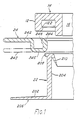
- Figure 1 is a cross-sectional view taken in an axial plane of one embodiment of ostomy coupling, showing the parts separated;
- Figure 2 is a view as in Figure 1 showing the two parts of the second coupling element assembled together;
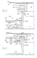
- Figure 3 is a view similar to Figure 1 showing the ostomy coupling in a coupled condition;
- Figure 4 is a front elevation of the coupling of Figures 1-3, but omitting the belt lugs; and
- Figure 5 is a side view of the assembled coupling on the same scale as Figure 4.
- For simplicity of illustration, in the sectional views of Figures 1-3, only one side of the coupling is shown. It will be understood that the coupling is of closed loop form and is intended to surround the stoma of the wearer. It is attached to the peristomal area of the body of the wearer in conventional manner by a pad of medical grade adhesive seen at 10 in Figure 2.
- The illustrated ostomy coupling is of substantially circular form but of course could be oval or any other convenient shape to surround the stoma. For brevity of description, a circular coupling is particularly described herein but the invention is not regarded as limited to circular/annular couplings.
- The illustrated ostomy coupling includes a first annular channel shaped coupling element for attachment to an ostomy bag. The
element 12 has asurface 14 to which one wall of the bag, having astomal orifice 16, is attached in any convenient manner. The channel shaped coupling element may be constructed in accordance with the teaching in British Patents 1 571 657 and 1 568 860. In Figure 2 the bag wall, which is the bag rear wall as worn, is seen at 18. - The
second coupling element 20 is designed for interengaging co-operation with thefirst coupling element 12 and includes afirst part 22 and asecond part 24. - The
first part 22 may be made as a single molding of EVA synthetic plastics material. It includes aflange 202 and a substantiallycylindrical chute member 204. Theflange 202 has asurface 206 by which the flange may be attached by heat welding or adhesive or other suitable manner to the medical gradeadhesive pad 10. Thechute member 204 encircles the stoma of the wearer, an has, at its end remote from theflange 202, a radially outwardly projectingrim 208 and an inwardly extending flexible anddeflectable seal strip 210. Theseal strip 210 is constructed in accordance with the teachings in British Patent 1 568 860. - The
second part 24 of the second coupling element is generally annular in form and may be made as a single molding of a polyester synthetic plastics material. it has an outwardly extendingflange 242 and arecess 244 which is designed to snuggly receive therim 208. Thepart 24 is, in use, sprung over thechute member 204 and can slide in an axial direction thereon. The assembled condition of these parts is seen in Figure 2. Thepart 24 is axially slidable relative to thechute member 204 of thepart 22 and, adjacent therecess 244, there is provided a radially outwardly extendingrim 246 whose chief purpose is to co-operate with an inwardly extendingrim 122 on the radiallyouter wall 124 of thecoupling element 12. - Assuming that the medical adhesive pad is attached to the peristomal area of a user, when the user wishes to attach the pouch, he (or she) lifts the
part 24 away from the body by placing his fingers under theflange 242, and moves it towards the outer end of thechute member 204. Thepart 24 is accordingly caused to slide axially outwardly in a telescopic manner relative to thechute member 204. When thepart 24 reaches the outer end the fingers are retained under theflange 242 and the bag and first coupling element are pressed in an axial direction using the thumbs of both hands, preferably placed approximately at opposite ends of the diameter, while the fingers remain under theflange 242 to absorb the reaction force. The resultant connected or coupled condition is seen in Figure 3, from which it will be observed that theannular coupling part 12 is retained on the second coupling element due to the interengagement of therims rim 208 inrecess 244. Theseal strip 210 serves to minimize any leakage of liquids. - Bearing in mind that the peristomal area is normally very tender and sensitive, it is an important advantage of the invention that the telescopically
slidable part 24 can be moved relative to thepart 22, while the latter is attached to the wearer, without applying any tensile force to the area over which the medical grade adhesive pad is in contact with and sticking to the wearer. Avoidance of such tensile forces, as well as avoidance of applying compressive forces when applying pressure to couple the two coupling elements, is a valuable advantageous feature of the invention. Moreover, the security of attachment using this coupling system is in every important respect fully the equal of that obtained with the system according to British Patent No. 1 571 657 which has enjoyed wide commercial success. - As illustrated in full outline, the
flange 242 is shown having a "cranked" shape at each side. As an optional alternative embodiment of the invention, this flange could be made (as shown at 243) to be a straight radial continuation of theportion 245 of thepart 24. The straight flange extends radially outwardly from the remaining ring portion of thepart 24 which containsrecess 244 andrim 246. - It will be appreciated that modifications can be made without departing from the invention. For example, while use of a
flexible strip 210 is considered preferable, other methods of achieving an adequate seal between theparts part 24 has been shown as a crankedflange 242 and alternatively as a straight and radially extendingflange 243, other shapes or configurations may be employed. A significant advantage of the illustrated construction is that the bodyside coupling element 20 may be employed with any one of the many millions of standard bagside coupling elements 12 that are already in widespread use.
Claims (10)
Priority Applications (1)
| Application Number | Priority Date | Filing Date | Title |
|---|---|---|---|
| AT89301764T ATE99530T1 (en) | 1988-03-23 | 1989-02-23 | OSTOMY COUPLING. |
Applications Claiming Priority (2)
| Application Number | Priority Date | Filing Date | Title |
|---|---|---|---|
| GB8806933 | 1988-03-23 | ||
| GB8806933A GB2215606B (en) | 1988-03-23 | 1988-03-23 | Ostomy coupling |
Publications (3)
| Publication Number | Publication Date |
|---|---|
| EP0334489A2 true EP0334489A2 (en) | 1989-09-27 |
| EP0334489A3 EP0334489A3 (en) | 1991-06-19 |
| EP0334489B1 EP0334489B1 (en) | 1994-01-05 |
Family
ID=10633972
Family Applications (1)
| Application Number | Title | Priority Date | Filing Date |
|---|---|---|---|
| EP89301764A Expired - Lifetime EP0334489B1 (en) | 1988-03-23 | 1989-02-23 | Ostomy coupling |
Country Status (8)
| Country | Link |
|---|---|
| US (1) | US4973324A (en) |
| EP (1) | EP0334489B1 (en) |
| JP (1) | JP2777182B2 (en) |
| AT (1) | ATE99530T1 (en) |
| CA (1) | CA1325570C (en) |
| DE (1) | DE68911966T2 (en) |
| ES (1) | ES2047663T3 (en) |
| GB (1) | GB2215606B (en) |
Cited By (6)
| Publication number | Priority date | Publication date | Assignee | Title |
|---|---|---|---|---|
| WO2007059775A1 (en) * | 2005-11-24 | 2007-05-31 | Coloplast A/S | Coupling assembly |
| US20100174256A1 (en) * | 2007-06-12 | 2010-07-08 | Oscar Rosengren | Coupling device and drainage assembly for collecting bodily waste excreted from a body drainage exit, and method of using the coupling and drainage assembly |
| DK201500164A1 (en) * | 2015-03-18 | 2016-10-10 | Multi-Lock Aps | An ostomy appliance |
| WO2020201689A1 (en) | 2019-03-29 | 2020-10-08 | Trio Healthcare Limited | Skin compatible silicone composition |
| WO2020201688A1 (en) | 2019-03-29 | 2020-10-08 | Trio Healthcare Limited | Foamed skin compatible silicone composition |
| US11103614B2 (en) | 2016-03-14 | 2021-08-31 | Trio Healthcare Limited | Skin compatible composition |
Families Citing this family (5)
| Publication number | Priority date | Publication date | Assignee | Title |
|---|---|---|---|---|
| DK361889D0 (en) * | 1989-07-21 | 1989-07-21 | Coloplast As | LOCKABLE LINK TO COLLECTORS AND CLOSES FOR BODIES |
| GB2237993A (en) * | 1989-11-17 | 1991-05-22 | Squibb & Sons Inc | Ostomy coupling |
| CA2028618C (en) * | 1989-11-17 | 2001-12-11 | Peter Leslie Steer | Ostomy coupling |
| GB2298794A (en) * | 1995-03-09 | 1996-09-18 | Squibb & Sons Inc | Ostomy coupling with intervening support ring |
| CN116648213A (en) * | 2020-12-31 | 2023-08-25 | 康沃特克科技公司 | Coupling systems for ostomy appliances |
Family Cites Families (22)
| Publication number | Priority date | Publication date | Assignee | Title |
|---|---|---|---|---|
| FR802823A (en) * | 1935-06-03 | 1936-09-16 | Bognier Et Burnet Ets | Improvement in devices for artificial anus or the like |
| GB1021145A (en) * | 1963-03-18 | 1966-03-02 | John Leslie Russell | Colostomy, ileostomy and ureterostomy appliance |
| GB1099455A (en) * | 1963-10-31 | 1968-01-17 | Joseph Benjamin Leigh | Improvements relating to colostomy appliances |
| US3736934A (en) * | 1971-09-21 | 1973-06-05 | A Hennessy | Surgical drainage appliance |
| GB1579875A (en) * | 1977-03-30 | 1980-11-26 | Kingsdown Medical Consultants | Coupling for an ostomy bag |
| NZ186585A (en) * | 1977-03-30 | 1981-03-16 | Kingsdown Medical Consultants | Coupling for joining pad or dressing to an ostomy bag |
| GB1568860A (en) * | 1978-03-21 | 1980-06-04 | Kingsdown Medical Consultants | Coupling for an ostomy bag |
| GB2121902B (en) * | 1982-03-11 | 1985-07-31 | Craig Med Prod Ltd | A coupling for an ostomy bag |
| US4419100A (en) * | 1982-03-16 | 1983-12-06 | Hollister Incorporated | Ostomy appliance and faceplate attachment therefor |
| AU572784B2 (en) * | 1982-06-24 | 1988-05-19 | E.R. Squibb & Sons, Inc. | Ostomy bag connection |
| GB2142399A (en) * | 1983-07-01 | 1985-01-16 | Craig Med Prod Ltd | Coupling for an ostomy bag |
| US4642107A (en) * | 1983-10-14 | 1987-02-10 | E. R. Squibb & Sons, Inc. | Adapter for use with two piece ostomy system |
| GB8403237D0 (en) * | 1984-02-07 | 1984-03-14 | Edwards J V | Ostomy appliance |
| DE3417183A1 (en) * | 1984-05-09 | 1985-11-14 | Gerald Dr. 8000 München Hauer | ANUS-PRAETER SUPPLY SYSTEM |
| GB2173403B (en) * | 1985-04-10 | 1988-10-05 | Craig Med Prod Ltd | Ostomy appliance |
| GB2177924A (en) * | 1985-07-16 | 1987-02-04 | Craig Med Prod Ltd | Side coupling element for ostomy appliances |
| GB2183481B (en) * | 1985-12-10 | 1989-10-11 | Craig Med Prod Ltd | Ostomy appliance |
| AU601194B2 (en) * | 1986-07-31 | 1990-09-06 | E.R. Squibb & Sons, Inc. | Ostomy coupling |
| GB8618693D0 (en) * | 1986-07-31 | 1986-09-10 | Craig Med Prod Ltd | Ostomy coupling |
| GB2201345B (en) * | 1987-01-27 | 1990-09-26 | Craig Med Prod Ltd | Coupling for ostomy and like bags |
| GB2201346B (en) * | 1987-02-05 | 1989-04-26 | Craig Med Prod Ltd | Ostomy coupling |
| GB2205041A (en) * | 1987-05-22 | 1988-11-30 | Craig Med Prod Ltd | Ostomy coupling |
-
1988
- 1988-03-23 GB GB8806933A patent/GB2215606B/en not_active Expired - Lifetime
-
1989
- 1989-02-23 EP EP89301764A patent/EP0334489B1/en not_active Expired - Lifetime
- 1989-02-23 ES ES89301764T patent/ES2047663T3/en not_active Expired - Lifetime
- 1989-02-23 DE DE68911966T patent/DE68911966T2/en not_active Expired - Fee Related
- 1989-02-23 AT AT89301764T patent/ATE99530T1/en not_active IP Right Cessation
- 1989-03-06 US US07/320,009 patent/US4973324A/en not_active Expired - Lifetime
- 1989-03-23 CA CA000594603A patent/CA1325570C/en not_active Expired - Fee Related
- 1989-03-23 JP JP1073697A patent/JP2777182B2/en not_active Expired - Fee Related
Cited By (9)
| Publication number | Priority date | Publication date | Assignee | Title |
|---|---|---|---|---|
| WO2007059775A1 (en) * | 2005-11-24 | 2007-05-31 | Coloplast A/S | Coupling assembly |
| US20100174256A1 (en) * | 2007-06-12 | 2010-07-08 | Oscar Rosengren | Coupling device and drainage assembly for collecting bodily waste excreted from a body drainage exit, and method of using the coupling and drainage assembly |
| DK201500164A1 (en) * | 2015-03-18 | 2016-10-10 | Multi-Lock Aps | An ostomy appliance |
| US11083617B2 (en) | 2015-03-18 | 2021-08-10 | Multi-Lock Aps | Ostomy device |
| US11103614B2 (en) | 2016-03-14 | 2021-08-31 | Trio Healthcare Limited | Skin compatible composition |
| EP4151244A1 (en) | 2016-03-14 | 2023-03-22 | Trio Healthcare Limited | Skin compatible composition |
| US11911531B2 (en) | 2016-03-14 | 2024-02-27 | Trio Healthcare Limited | Skin compatible composition |
| WO2020201689A1 (en) | 2019-03-29 | 2020-10-08 | Trio Healthcare Limited | Skin compatible silicone composition |
| WO2020201688A1 (en) | 2019-03-29 | 2020-10-08 | Trio Healthcare Limited | Foamed skin compatible silicone composition |
Also Published As
| Publication number | Publication date |
|---|---|
| EP0334489B1 (en) | 1994-01-05 |
| US4973324A (en) | 1990-11-27 |
| CA1325570C (en) | 1993-12-28 |
| ES2047663T3 (en) | 1994-03-01 |
| GB2215606A (en) | 1989-09-27 |
| DE68911966D1 (en) | 1994-02-17 |
| DE68911966T2 (en) | 1994-07-14 |
| JPH01299552A (en) | 1989-12-04 |
| GB2215606B (en) | 1992-02-12 |
| JP2777182B2 (en) | 1998-07-16 |
| EP0334489A3 (en) | 1991-06-19 |
| ATE99530T1 (en) | 1994-01-15 |
| GB8806933D0 (en) | 1988-04-27 |
Similar Documents
| Publication | Publication Date | Title |
|---|---|---|
| EP0274862B1 (en) | Ostomy bag coupling | |
| CA2174164C (en) | Ostomy coupling | |
| EP0429199B1 (en) | Ostomy coupling | |
| US4834732A (en) | Ostomy coupling | |
| US4973324A (en) | Ostomy coupling | |
| US5549588A (en) | Coupling device for ostomy pouch | |
| CA1278484C (en) | Ostomy appliance | |
| EP0353904B1 (en) | Ostomy system | |
| US4867749A (en) | Urostomy appliance | |
| EP0171404B1 (en) | Ostomy appliance | |
| US4781708A (en) | Telescoping coupling for an ostomy appliance | |
| JPH0367413B2 (en) | ||
| EP0347025B1 (en) | Coupling for attaching an ostomy pouch to a medical grade adhesive pad | |
| US4775373A (en) | Ostomy appliance | |
| US5495858A (en) | Male incontinence device | |
| US5709674A (en) | Ostomy coupling | |
| GB2237993A (en) | Ostomy coupling | |
| JP2873018B2 (en) | Coupling for colostomy bags | |
| GB2190841A (en) | Ostomy appliance | |
| GB2148120A (en) | Ostomy bag coupling |
Legal Events
| Date | Code | Title | Description |
|---|---|---|---|
| PUAI | Public reference made under article 153(3) epc to a published international application that has entered the european phase |
Free format text: ORIGINAL CODE: 0009012 |
|
| AK | Designated contracting states |
Kind code of ref document: A2 Designated state(s): AT BE CH DE ES FR GB GR IT LI LU NL SE |
|
| 17P | Request for examination filed |
Effective date: 19901219 |
|
| PUAL | Search report despatched |
Free format text: ORIGINAL CODE: 0009013 |
|
| AK | Designated contracting states |
Kind code of ref document: A3 Designated state(s): AT BE CH DE ES FR GB GR IT LI LU NL SE |
|
| 17Q | First examination report despatched |
Effective date: 19921028 |
|
| RBV | Designated contracting states (corrected) |
Designated state(s): AT BE CH DE ES FR GR IT LI LU NL SE |
|
| GRAA | (expected) grant |
Free format text: ORIGINAL CODE: 0009210 |
|
| AK | Designated contracting states |
Kind code of ref document: B1 Designated state(s): AT BE CH DE ES FR GR IT LI LU NL SE |
|
| REF | Corresponds to: |
Ref document number: 99530 Country of ref document: AT Date of ref document: 19940115 Kind code of ref document: T |
|
| ET | Fr: translation filed | ||
| REF | Corresponds to: |
Ref document number: 68911966 Country of ref document: DE Date of ref document: 19940217 |
|
| REG | Reference to a national code |
Ref country code: ES Ref legal event code: FG2A Ref document number: 2047663 Country of ref document: ES Kind code of ref document: T3 |
|
| ITF | It: translation for a ep patent filed | ||
| EPTA | Lu: last paid annual fee | ||
| REG | Reference to a national code |
Ref country code: GR Ref legal event code: FG4A Free format text: 3010698 |
|
| PLBE | No opposition filed within time limit |
Free format text: ORIGINAL CODE: 0009261 |
|
| STAA | Information on the status of an ep patent application or granted ep patent |
Free format text: STATUS: NO OPPOSITION FILED WITHIN TIME LIMIT |
|
| 26N | No opposition filed | ||
| EAL | Se: european patent in force in sweden |
Ref document number: 89301764.0 |
|
| PGFP | Annual fee paid to national office [announced via postgrant information from national office to epo] |
Ref country code: AT Payment date: 20000211 Year of fee payment: 12 |
|
| PGFP | Annual fee paid to national office [announced via postgrant information from national office to epo] |
Ref country code: LU Payment date: 20000221 Year of fee payment: 12 |
|
| PGFP | Annual fee paid to national office [announced via postgrant information from national office to epo] |
Ref country code: GR Payment date: 20000225 Year of fee payment: 12 |
|
| PGFP | Annual fee paid to national office [announced via postgrant information from national office to epo] |
Ref country code: CH Payment date: 20000228 Year of fee payment: 12 |
|
| PGFP | Annual fee paid to national office [announced via postgrant information from national office to epo] |
Ref country code: BE Payment date: 20000412 Year of fee payment: 12 |
|
| PG25 | Lapsed in a contracting state [announced via postgrant information from national office to epo] |
Ref country code: LU Free format text: LAPSE BECAUSE OF NON-PAYMENT OF DUE FEES Effective date: 20010223 Ref country code: AT Free format text: LAPSE BECAUSE OF NON-PAYMENT OF DUE FEES Effective date: 20010223 |
|
| PG25 | Lapsed in a contracting state [announced via postgrant information from national office to epo] |
Ref country code: CH Free format text: LAPSE BECAUSE OF NON-PAYMENT OF DUE FEES Effective date: 20010228 Ref country code: LI Free format text: LAPSE BECAUSE OF NON-PAYMENT OF DUE FEES Effective date: 20010228 Ref country code: BE Free format text: LAPSE BECAUSE OF NON-PAYMENT OF DUE FEES Effective date: 20010228 Ref country code: GR Free format text: LAPSE BECAUSE OF NON-PAYMENT OF DUE FEES Effective date: 20010228 |
|
| BERE | Be: lapsed |
Owner name: E.R. SQUIBB & SONS INC. Effective date: 20010228 |
|
| REG | Reference to a national code |
Ref country code: CH Ref legal event code: PL |
|
| PGFP | Annual fee paid to national office [announced via postgrant information from national office to epo] |
Ref country code: NL Payment date: 20070204 Year of fee payment: 19 |
|
| PGFP | Annual fee paid to national office [announced via postgrant information from national office to epo] |
Ref country code: SE Payment date: 20070206 Year of fee payment: 19 |
|
| PGFP | Annual fee paid to national office [announced via postgrant information from national office to epo] |
Ref country code: DE Payment date: 20070215 Year of fee payment: 19 |
|
| PGFP | Annual fee paid to national office [announced via postgrant information from national office to epo] |
Ref country code: ES Payment date: 20070327 Year of fee payment: 19 |
|
| PGFP | Annual fee paid to national office [announced via postgrant information from national office to epo] |
Ref country code: IT Payment date: 20070626 Year of fee payment: 19 |
|
| PGFP | Annual fee paid to national office [announced via postgrant information from national office to epo] |
Ref country code: FR Payment date: 20070208 Year of fee payment: 19 |
|
| EUG | Se: european patent has lapsed | ||
| NLV4 | Nl: lapsed or anulled due to non-payment of the annual fee |
Effective date: 20080901 |
|
| PG25 | Lapsed in a contracting state [announced via postgrant information from national office to epo] |
Ref country code: NL Free format text: LAPSE BECAUSE OF NON-PAYMENT OF DUE FEES Effective date: 20080901 |
|
| REG | Reference to a national code |
Ref country code: FR Ref legal event code: ST Effective date: 20081031 |
|
| PG25 | Lapsed in a contracting state [announced via postgrant information from national office to epo] |
Ref country code: DE Free format text: LAPSE BECAUSE OF NON-PAYMENT OF DUE FEES Effective date: 20080902 Ref country code: SE Free format text: LAPSE BECAUSE OF NON-PAYMENT OF DUE FEES Effective date: 20080224 |
|
| PG25 | Lapsed in a contracting state [announced via postgrant information from national office to epo] |
Ref country code: FR Free format text: LAPSE BECAUSE OF NON-PAYMENT OF DUE FEES Effective date: 20080229 |
|
| REG | Reference to a national code |
Ref country code: ES Ref legal event code: FD2A Effective date: 20080225 |
|
| PG25 | Lapsed in a contracting state [announced via postgrant information from national office to epo] |
Ref country code: ES Free format text: LAPSE BECAUSE OF NON-PAYMENT OF DUE FEES Effective date: 20080225 |
|
| PG25 | Lapsed in a contracting state [announced via postgrant information from national office to epo] |
Ref country code: IT Free format text: LAPSE BECAUSE OF NON-PAYMENT OF DUE FEES Effective date: 20080223 |