EP0333325B1 - Ink drop control system with temperature compensation - Google Patents
Ink drop control system with temperature compensation Download PDFInfo
- Publication number
- EP0333325B1 EP0333325B1 EP89301458A EP89301458A EP0333325B1 EP 0333325 B1 EP0333325 B1 EP 0333325B1 EP 89301458 A EP89301458 A EP 89301458A EP 89301458 A EP89301458 A EP 89301458A EP 0333325 B1 EP0333325 B1 EP 0333325B1
- Authority
- EP
- European Patent Office
- Prior art keywords
- ink
- temperature
- flow rate
- change
- flow
- Prior art date
- Legal status (The legal status is an assumption and is not a legal conclusion. Google has not performed a legal analysis and makes no representation as to the accuracy of the status listed.)
- Expired - Lifetime
Links
- 230000008859 change Effects 0.000 claims description 45
- 239000000203 mixture Substances 0.000 claims description 30
- 238000000034 method Methods 0.000 claims description 17
- 230000001419 dependent effect Effects 0.000 claims description 11
- 230000015572 biosynthetic process Effects 0.000 claims description 4
- 239000000976 ink Substances 0.000 description 131
- 239000002904 solvent Substances 0.000 description 19
- 239000012530 fluid Substances 0.000 description 14
- 238000005259 measurement Methods 0.000 description 10
- 230000006870 function Effects 0.000 description 8
- 239000007788 liquid Substances 0.000 description 6
- 230000006399 behavior Effects 0.000 description 4
- 230000009471 action Effects 0.000 description 3
- 238000009529 body temperature measurement Methods 0.000 description 3
- 230000007423 decrease Effects 0.000 description 3
- 239000000758 substrate Substances 0.000 description 3
- 235000014676 Phragmites communis Nutrition 0.000 description 2
- 238000004364 calculation method Methods 0.000 description 2
- 238000009434 installation Methods 0.000 description 2
- 230000011664 signaling Effects 0.000 description 2
- 239000007787 solid Substances 0.000 description 2
- 238000004458 analytical method Methods 0.000 description 1
- 230000008901 benefit Effects 0.000 description 1
- 238000001816 cooling Methods 0.000 description 1
- 238000010586 diagram Methods 0.000 description 1
- 238000009826 distribution Methods 0.000 description 1
- 238000001035 drying Methods 0.000 description 1
- 239000000975 dye Substances 0.000 description 1
- 230000000694 effects Effects 0.000 description 1
- 230000008030 elimination Effects 0.000 description 1
- 238000003379 elimination reaction Methods 0.000 description 1
- 238000009472 formulation Methods 0.000 description 1
- 238000010438 heat treatment Methods 0.000 description 1
- 238000004519 manufacturing process Methods 0.000 description 1
- 230000000704 physical effect Effects 0.000 description 1
- 238000002360 preparation method Methods 0.000 description 1
- 229920005989 resin Polymers 0.000 description 1
- 239000011347 resin Substances 0.000 description 1
- 230000004044 response Effects 0.000 description 1
- 230000001360 synchronised effect Effects 0.000 description 1
Images


Classifications
-
- B—PERFORMING OPERATIONS; TRANSPORTING
- B41—PRINTING; LINING MACHINES; TYPEWRITERS; STAMPS
- B41J—TYPEWRITERS; SELECTIVE PRINTING MECHANISMS, i.e. MECHANISMS PRINTING OTHERWISE THAN FROM A FORME; CORRECTION OF TYPOGRAPHICAL ERRORS
- B41J2/00—Typewriters or selective printing mechanisms characterised by the printing or marking process for which they are designed
- B41J2/005—Typewriters or selective printing mechanisms characterised by the printing or marking process for which they are designed characterised by bringing liquid or particles selectively into contact with a printing material
- B41J2/01—Ink jet
- B41J2/07—Ink jet characterised by jet control
- B41J2/072—Ink jet characterised by jet control by thermal compensation
-
- B—PERFORMING OPERATIONS; TRANSPORTING
- B41—PRINTING; LINING MACHINES; TYPEWRITERS; STAMPS
- B41J—TYPEWRITERS; SELECTIVE PRINTING MECHANISMS, i.e. MECHANISMS PRINTING OTHERWISE THAN FROM A FORME; CORRECTION OF TYPOGRAPHICAL ERRORS
- B41J2/00—Typewriters or selective printing mechanisms characterised by the printing or marking process for which they are designed
- B41J2/005—Typewriters or selective printing mechanisms characterised by the printing or marking process for which they are designed characterised by bringing liquid or particles selectively into contact with a printing material
- B41J2/01—Ink jet
- B41J2/07—Ink jet characterised by jet control
-
- B—PERFORMING OPERATIONS; TRANSPORTING
- B41—PRINTING; LINING MACHINES; TYPEWRITERS; STAMPS
- B41J—TYPEWRITERS; SELECTIVE PRINTING MECHANISMS, i.e. MECHANISMS PRINTING OTHERWISE THAN FROM A FORME; CORRECTION OF TYPOGRAPHICAL ERRORS
- B41J2/00—Typewriters or selective printing mechanisms characterised by the printing or marking process for which they are designed
- B41J2/005—Typewriters or selective printing mechanisms characterised by the printing or marking process for which they are designed characterised by bringing liquid or particles selectively into contact with a printing material
- B41J2/01—Ink jet
- B41J2/17—Ink jet characterised by ink handling
- B41J2/195—Ink jet characterised by ink handling for monitoring ink quality
Definitions
- This invention relates to the field of drop marking systems of the type in which a liquid ink is forced under pressure through a nozzle which converts the liquid into droplets which can then be controlled by various means while projected toward a substrate for marking purposes.
- Examples of such systems include the familiar ink jet marking systems used for high speed label printing, product identification and the like, although there are other drop marking systems known in the art.
- One particular type of system which advantageously employs the present invention is the continuous stream, synchronous ink jet printer.
- Such a system typically includes an ink reservoir and a remotely located nozzle connected to the reservoir by a conduit. Ink is forced under pressure from the reservoir to the nozzle which emits a continuous stream of ink drops.
- the ink which is electrically conductive, is provided with a charge as the drops leave the nozzle.
- the drops then pass through a deflection field which causes selected drops to be deflected so that some of the drops are deposited onto a substrate while the remaining drops are returned to the reservoir by a suitable ink return means.
- control system adjusts the flow rate by controlling the addition of make-up solvent to the ink reservoir.
- the viscosity of the ink is thereby adjusted so as to maintain drop velocity substantially constant.
- present ink jet fluid control systems employ flow meters, of the type disclosed in the '712 patent, to control the addition of solvent to the ink.
- viscosity and, therefore, flow time vary as a function of both compositional changes in the ink and temperature.
- the prior art system did not teach any correction for temperature variation.
- solvent may be added to the system when the flow time is too high, principally due to a temperature decrease rather than solvent loss. This can cause the aforementioned wide variation in the ink's composition resulting in undesirable operating characteristics.
- solvent may be withheld from the system when the flow time is kept low by a temperature increase even though solvent may be needed as a result of evaporative losses due to system operation.
- the present invention measures a change in temperature of the ink at selected intervals and calculates the flow time difference for this temperature change. The result is used to alter the reference flow time used to control the addition of solvent to the system. This results in elimination of the ambiguity due to temperature changes during system operation.
- a specific flow time reference value is accessed from the ROM and used by the microprocessor system to control addition of solvent.
- Such a system cannot take into account the many variations in initial ink viscosity, calibration settings, capillary dimensions, and other system parameters which affect flow time and which differ from installation to installation for the same system or different printer systems of a similar type.
- the Erskine system depends upon absolute temperature and pressure values and, therefore, inaccuracies, due to the miscalibration of the temperature or pressure sensor, can interfere with the intended operation of the system.
- a drop marking system may include means for causing ink to flow through a conduit to a nozzle to form a stream of ink drops, means for measuring the flow rate of the ink to the nozzle and an ink composition control means responsive to a controller to control the ink composition dependent on the measured flow rate.
- a drop marking system has a temperature sensing means provided for periodically measuring any change in the temperature of the ink at a point prior to the formation of the stream of ink drops, the controller is responsive to any change in temperature to recalculate a preset reference value (SP) using said temperature change, and the ink composition control means is responsive to the controller to control the ink composition dependent on the variation of the ink flow rate from the recalculated reference value (SP').
- the temperature sensing means may preferably be located adjacent the nozzle to measure any change in the temperature of the ink just before it reaches the nozzle.
- the controller may include means to identify changes in the flow rate of the ink from a preset reference value, and the controller may be arranged to control the ink composition dependent on such change of the flow rate as well as the change in temperature.
- the time measuring means is preferably arranged to identify deviations from a preset reference time.
- a method of drop marking may include passing ink to a nozzle to produce a stream of ink drops, measuring the flow rate of the ink passing to the nozzle, and controlling the ink composition dependent on the measured flow rate.
- a method of drop marking includes periodically measuring any change in the temperature of the ink at a point before ink drop formation, using any change in temperature to recalculate a preset reference value (SP), and controlling the ink composition dependant on the variation of the ink flow rate from the recalculated reference value (SP').
- the method preferably includes measuring any change in the temperature of the ink just before it reaches the nozzle.
- the method may include identifying changes in the flow rate of the ink from a preset reference value (SP), and controlling the ink composition dependent on such change of the flow rate as well as the change in temperature.
- SP preset reference value
- the method preferably includes identifying changes in the flow rate of the ink as deviations from a preset reference time (SP).
- the present invention accordingly provides an improved control system related to the method and apparatus disclosed in U.S. Patent 4,555,712 but in which the effects of temperature change during system operation are accounted for.
- the present invention enables the provision of a feedback control for a fluid delivery system in which both flow time and temperature are monitored, whereby the desired properties of the fluid can be maintained substantially constant by selective adjustment of the flow time.
- the present invention teaches the provision of a system in which temperature differences are employed rather than absolute temperature values, whereby inaccuracies due to miscalibration of the temperature sensor are eliminated.
- the present invention also teaches the provision of a dynamic control system which can take into account flow time differences between identical systems due, for example, to manufacturing tolerances or to initial set-up variations.
- a dynamic system periodically recalculates a reference flow time based on a particular system's operating characteristics. System to system variations are, therefore, irrelevant because only flow time and temperature differences relative to initial or preceding values are considered.
- the present invention enables the periodical calculation of a new reference flow time after measuring the ink temperature or a temperature representative thereof.
- This new temperature reading is converted to a temperature difference between the present temperature and the most recent temperature measurement or the temperature measured initially during system set-up.
- the temperature difference is used to calculate a new reference flow time. Actual flow times are then compared to this new, reference flow time and, if necessary, solvent is added accordingly.
- an ink drop velocity control system of the type described in detail in U.S. Patent 4,555,712 is illustrated. Reference to that patent is made for the details of the system beyond those described herein.
- an ink jet nozzle 12 has an orifice 14. The nozzle is acted upon by a piezo electric device 18 causing drops to be formed. The drops pass a charging electrode 17 and an electrical deflection field schematically represented by plates 19. Depending on their charge the drops are directed onto a substrate 27 for marking or are returned to the system via a collector 26.
- the supply tank 22, according to the invention described in the '712 patent, is repetitively filled by suitable means which comprise a part of the recirculation system designated generally at 24 of which the collector 26 is a part. The details of the recirculation system are described in the aforementioned patent in connection with Figure 2 thereof.
- a pressure source for example a gas pressure source 30, is provided as detailed in the '712 patent.
- an in-line fluid pump 31 having a pressure regulator and bypass line (not shown) connected to the output thereof in a manner understood by those skilled in the art may be employed to provide ink from the tank 22 to the nozzle 12.
- the supply tank or reservoir chamber 22 is filled with an electrically conductive ink to some arbitrarily determined level as indicated at C for example.
- the level of ink in the tank decreases until it reaches a second, arbitrarily determined level as indicated at A.
- a first level detector 32 is activated signalling an electronic controller 34 which initiates a timing interval.
- Ink continues to flow out of the nozzle causing a drop in the tank level until, at some later time, the level of the ink in the supply tank reaches a third, arbitrarily determined level as indicated at B.
- a second liquid level detector 36 is activated signalling the controller 34 to cease measurement.
- the controller When the controller receives this second signal, it compares the time interval or the average of a succession of such intervals to an established reference interval. If necessary the controller then initiates suitable action, as will be described, to cause the ink flow rate through the nozzle to change such that successive time intervals will approach the reference interval.
- the level of ink in the tank 22 after passing point B may continue to fall until some suitable level as indicated at D is reached.
- the ink recirculation system 24 refills the supply tank.
- point D will usually be the same as point B so that upon completing measurement of the time interval between points A and B, the recirculation system will refill the tank to level C in preparation for the next time interval measurement.
- the liquid level detectors 32 and 36 provide their input to an electronic controller 34.
- the detectors may be of any commercially available type as, for example, a magnetic float which actuates a reed switch whereby a change in state of the reed switch (open to close or vice versa) is detected by the controller 34.
- the controller may be a solid state logic system or a programmed computer as, for example, a microprocessor computer system such as the Intel 8031 microcontroller. Responsive to the switches 32 and 36, the controller 34 will activate one or more output devices under its control as indicated schematically in FIG. 1. These devices include ink heating and/or cooling means 40, pressure control means 42 or solvent control means 44. In addition, the controller may operate an information display, such as a LED or LCD display 46, to provide information to an operator concerning the status of the system.
- an information display such as a LED or LCD display 46
- the specific means 40 through 44 are discussed in detail in connection with the embodiments of FIGS. 2 through 6 of the '712 patent. However, it can be seen that the invention is directly responsive to the flow rate data derived form the flow of ink between points A and B.
- the electronic controller operates the system selectively to adjust the flow rate of the ink through nozzle orifice 14, preferably by adjusting the solvent component of the ink composition, in a manner that assures consistency of the ink composition during operation of the system.
- the controller is provided with a reference time for the flow of an established quantity of ink, that is, the quantity of ink between the points A and B.
- a reference time for the flow of an established quantity of ink, that is, the quantity of ink between the points A and B.
- the velocity of the drops is set thereby establishing a reference flow time. For example, pressure is adjusted until the desired drop velocity is obtained.
- the controller stores and averages a number of measurements of time required for the ink to pass between levels A and B. When the required number of measurements have been taken the reference time is compared against the average time of the actual measurements. If the actual measurements are greater than the reference, it is necessary to increase flow through the nozzle orifice. Preferably, this is effected by adding solvent to lower ink viscosity.
- the computed total is less than the reference value, it is necessary to modify the ink composition to decrease the flow through the nozzle orifice and opposite actions are required. For example, simply not adding solvent to the ink will increase its viscosity due to the normal evaporative losses as the ink circulates through the marking system.
- the controller repeats the above actions to maintain a substantially constant measured time interval.
- the rate at which the measurement cycles occur is a function of the size of the supply tank, typically on the order of 10 ml, the precision required and a number of related factors including whether or not the system is utilized for one ink jet nozzle or multiple nozzles. For example, with a single ink jet head it may be sufficient to check flow rate at approximately one minute intervals but shorter or longer intervals may also be employed.
- a temperature sensor is provided in the present invention.
- the temperature sensor 80 is preferably located just behind the nozzle 12 as close to the drop stream as physically possible. In this way the temperature that is measured is essentially the temperature of the ink flowing through the nozzle orifice. While this is the preferred manner in which temperature sensing is accomplished, it should also be recognized that the temperature sensor may instead be located away from the nozzle at a location where it will still provide a temperature reading representative of the ink temperature.
- the output of the temperature sensor 80 is provided to the electronic controller 34 along with the flow data from the liquid level detectors 32 and 36.
- the electronic controller determines whether the reference flow time requires change (as explained subsequently) and if a change is warranted then it employs one or more of the control means to correct any detected variation in flow rate.
- This preferred embodiment utilizes a solvent control system in conjunction with the electronic controller 34. This embodiment is described in detail in the '712 patent except for the temperature compensation aspects of the present invention.
- the operator enters a two digit number, gamma, related to the characteristics of the ink and the system and sets the ink stream velocity to a desired value.
- Gamma is calculated based on the viscosity properties of a given ink composition and certain system parameters.
- the operator then calls the initialization routine shown in Figure 3.
- the system determines a reference flow time (Set Point), by the method described in the '712 patent and summarized earlier herein.
- the system also measures the ink temperature provided from sensor 80, obtaining an initial value T.
- the system is now operational and will utilize the flow rate information provided at initialization until such time as a recalculation of the set point occurs.
- Subsequent values of the reference Set Point can be calculated based upon the detected temperature difference between the current temperature and either the most recent temperature measurement or the temperature measured at the time of initial set-up of the system. In this way changes in operating temperature are compensated for dynamically.
- Gamma is related predominantly to the physical properties of the ink and may be thought of as a temperature responsive factor for a given ink.
- Figure 4 illustrates the relationship between viscosity and temperature for typical ink compositions suitable for use in the present invention. If the system operator wishes, a value of gamma different than the gamma specified for a given ink can be entered into the system to obtain specialized response characteristics. This is an advantage of the present invention over that disclosed in the Erskine Patent 4,714,931 which uses temperature compensation values stored in a read only memory.
- the factor gamma can be derived through mathematical analysis as follows.
- a model fluid system having a nozzle with orifice diameter d and some effective length l.
- d nozzle with orifice diameter
- l nozzle with orifice diameter
- ⁇ surface tension
- ⁇ viscosity »
- P input 32» ⁇ (v/d2)dl + 4 ⁇ /d + ⁇ V str /2
- P input is the input pressure of the system
- v the fluid velocity at any point in the system
- v str is the velocity of the free jet.
- Eqns. (5) and (6) can be used to determine the relationship between flow time changes and fluid viscosity changes, namely: Eqn. (7) gives the change in flow time as a function of the change in fluid viscosity for a system with the specified parameters. To calculate the percent change in the flow time, we simply divide the result of eqn. (7) by the flow time t f : Using eqn.
- the flow time is represented in eqn. (10) by t.
- each ink considered will have its own unique value of gamma, since gamma depends on both the specific ink viscosity behavior with temperature and the value of (1/t)(dt/d» ), which also depend on viscosity.
- the invention periodically recalculates a reference flow time based initially on a particular system's desired flow time at set up. In performing the recalculation the reference flow time is adjusted to compensate for changes in temperature from the preceding calculation of the reference flow time or from the initial value of the flow time.
- the result is a dynamic system which can control flow rate according to a defined relation while maintaining the ink composition substantially the same regardless of variations between systems and changes in operational temperatures.
- the actual temperature of the ink sensor is not critical, only the change in temperature from measurement to measurement is important. In other words, absolute knowledge of the ink temperature is not required.
Landscapes
- Engineering & Computer Science (AREA)
- Quality & Reliability (AREA)
- Ink Jet (AREA)
- Particle Formation And Scattering Control In Inkjet Printers (AREA)
Description
- This invention relates to the field of drop marking systems of the type in which a liquid ink is forced under pressure through a nozzle which converts the liquid into droplets which can then be controlled by various means while projected toward a substrate for marking purposes. Examples of such systems include the familiar ink jet marking systems used for high speed label printing, product identification and the like, although there are other drop marking systems known in the art. One particular type of system which advantageously employs the present invention is the continuous stream, synchronous ink jet printer. Such a system typically includes an ink reservoir and a remotely located nozzle connected to the reservoir by a conduit. Ink is forced under pressure from the reservoir to the nozzle which emits a continuous stream of ink drops. The ink, which is electrically conductive, is provided with a charge as the drops leave the nozzle. The drops then pass through a deflection field which causes selected drops to be deflected so that some of the drops are deposited onto a substrate while the remaining drops are returned to the reservoir by a suitable ink return means.
- It is known in the prior art to sense the flow of the ink from the reservoir and adjust ink parameters to maintain a desired flow rate. This teaching is found in the present assignee's prior U.S. Patent No. 4,555,712. In the '712 patent a method and apparatus are disclosed which provide a means for determining and maintaining ink drop velocity substantially constant and does so in a manner which is substantially more accurate than was obtainable in the prior art.
- In a preferred embodiment of the '712 patent the control system adjusts the flow rate by controlling the addition of make-up solvent to the ink reservoir. The viscosity of the ink is thereby adjusted so as to maintain drop velocity substantially constant.
- Experience with this system has demonstrated that the percentage of solids (dyes and resins) in the ink composition varies, due to solvent addition, by as much as ten to forty percent from its initial composition in the course of the system operating to maintain substantially constant drop velocity as the temperature of the ink varies. Such a wide shift in composition affects other characteristics important in an ink jet system, such as ink drying time, drop break off point and even the charging characteristics of the ink drops. As a consequence, viscosity variations, due principally to temperature fluctuations during operation of the equipment, must be recognized by the control system so that solvent is added in a manner that does not excessively modify the formulation of the inks used in the system.
- More specifically, present ink jet fluid control systems employ flow meters, of the type disclosed in the '712 patent, to control the addition of solvent to the ink. However, viscosity and, therefore, flow time, vary as a function of both compositional changes in the ink and temperature. The prior art system did not teach any correction for temperature variation. As a result, solvent may be added to the system when the flow time is too high, principally due to a temperature decrease rather than solvent loss. This can cause the aforementioned wide variation in the ink's composition resulting in undesirable operating characteristics. Conversely, solvent may be withheld from the system when the flow time is kept low by a temperature increase even though solvent may be needed as a result of evaporative losses due to system operation.
- Accordingly, it is desired to provide a system which can compensate for both types of viscosity variations (compositional changes and temperature changes).
- The present invention measures a change in temperature of the ink at selected intervals and calculates the flow time difference for this temperature change. The result is used to alter the reference flow time used to control the addition of solvent to the system. This results in elimination of the ambiguity due to temperature changes during system operation.
- It is known in the art to employ a flow meter and a temperature sensor to determine a representative viscosity of a fluid, such as ink. Exemplary of this type of system is U.S. Patent 4,714,931 to Erskine. As disclosed in connection with Figures 1 and 2 of that patent, the addition of solvent is controlled by a microprocessor which receives as inputs flow data from a
viscometer 12, pressure from a transducer and temperature data. The Erskine patent, however, employs temperature and pressure values stored in a look up table resident in a read only memory (ROM) to provide reference flow times. - Depending upon the actual temperature and pressure detected, a specific flow time reference value is accessed from the ROM and used by the microprocessor system to control addition of solvent. Such a system cannot take into account the many variations in initial ink viscosity, calibration settings, capillary dimensions, and other system parameters which affect flow time and which differ from installation to installation for the same system or different printer systems of a similar type. Furthermore, the Erskine system depends upon absolute temperature and pressure values and, therefore, inaccuracies, due to the miscalibration of the temperature or pressure sensor, can interfere with the intended operation of the system.
- It is known from US Patent 4,555,712 that a drop marking system may include means for causing ink to flow through a conduit to a nozzle to form a stream of ink drops, means for measuring the flow rate of the ink to the nozzle and an ink composition control means responsive to a controller to control the ink composition dependent on the measured flow rate.
- According to the present invention a drop marking system has a temperature sensing means provided for periodically measuring any change in the temperature of the ink at a point prior to the formation of the stream of ink drops, the controller is responsive to any change in temperature to recalculate a preset reference value (SP) using said temperature change, and the ink composition control means is responsive to the controller to control the ink composition dependent on the variation of the ink flow rate from the recalculated reference value (SP'). The temperature sensing means may preferably be located adjacent the nozzle to measure any change in the temperature of the ink just before it reaches the nozzle.
- The controller may include means to identify changes in the flow rate of the ink from a preset reference value, and the controller may be arranged to control the ink composition dependent on such change of the flow rate as well as the change in temperature. In the case where the flow rate of the ink is measured as the time interval required for a predetermined volume of ink to flow into the conduit, the time measuring means is preferably arranged to identify deviations from a preset reference time.
- A parameter input means is preferably provided for inputting to the controller, for recalculating the preset reference (SP), an ink specific parameter (gamma) relating the viscosity variation of a given ink with the temperature of the ink, the recalculated reference value (SP') being computed from the formula:-

- SP
- = the present preset reference
- SP'
- = the recalculated reference, and
- deltaT
- = the change in temperature since the previous determination of SP
- m
- = the slope of the viscosity/temperature graph for a given ink over a region of interest,
- t
- = the flow time (time interval for a predetermined volume of ink to flow through an orifice, i.e. flow rate), and
- »
- = viscosity
- It is also known from US Patent No. 4,555,712 that a method of drop marking may include passing ink to a nozzle to produce a stream of ink drops, measuring the flow rate of the ink passing to the nozzle, and controlling the ink composition dependent on the measured flow rate.
- According to the present invention a method of drop marking includes periodically measuring any change in the temperature of the ink at a point before ink drop formation, using any change in temperature to recalculate a preset reference value (SP), and controlling the ink composition dependant on the variation of the ink flow rate from the recalculated reference value (SP'). The method preferably includes measuring any change in the temperature of the ink just before it reaches the nozzle.
- The method may include identifying changes in the flow rate of the ink from a preset reference value (SP), and controlling the ink composition dependent on such change of the flow rate as well as the change in temperature. In the case where the flow rate of the ink is measured as the time interval required for a predetermined volume of ink to flow towards the nozzle, the method preferably includes identifying changes in the flow rate of the ink as deviations from a preset reference time (SP).
- The method preferably includes determining the preset reference (SP) according to:-

- SP
- = the present preset reference,
- SP'
- = the recalculated reference,
- gamma
- = an ink specific parameter relating variation of viscosity of a given ink with the temperature of the ink, and
- deltaT
- = the change in temperature since the previous determination of SP
- m
- = the slope of the viscosity/temperature graph for a given ink over a region of interest,
- t
- = the flow time (time interval for a predetermined volume of ink to flow through an orifice, i.e. flow rate), and
- »
- = viscosity
- The present invention accordingly provides an improved control system related to the method and apparatus disclosed in U.S. Patent 4,555,712 but in which the effects of temperature change during system operation are accounted for.
- The present invention enables the provision of a feedback control for a fluid delivery system in which both flow time and temperature are monitored, whereby the desired properties of the fluid can be maintained substantially constant by selective adjustment of the flow time.
- The present invention teaches the provision of a system in which temperature differences are employed rather than absolute temperature values, whereby inaccuracies due to miscalibration of the temperature sensor are eliminated.
- The present invention also teaches the provision of a dynamic control system which can take into account flow time differences between identical systems due, for example, to manufacturing tolerances or to initial set-up variations. Such a dynamic system periodically recalculates a reference flow time based on a particular system's operating characteristics. System to system variations are, therefore, irrelevant because only flow time and temperature differences relative to initial or preceding values are considered.
- The present invention enables the periodical calculation of a new reference flow time after measuring the ink temperature or a temperature representative thereof. This new temperature reading is converted to a temperature difference between the present temperature and the most recent temperature measurement or the temperature measured initially during system set-up. The temperature difference is used to calculate a new reference flow time. Actual flow times are then compared to this new, reference flow time and, if necessary, solvent is added accordingly.
- The invention is now described, by way of example only, with reference to the accompanying drawings, in which:-
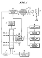
- Figure 1 is a schematic drawing of an ink jet system similar to the system detailed in U.S. Patent 4,555,712 but modified to incorporate the additional elements of the present invention.
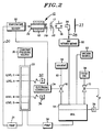
- Figure 2 is a drawing similar to Figure 2 or U.S. Patent 4,555,712 but modified to illustrate a preferred embodiment of the present invention.
- Figure 3 is a flow diagram suitable for use in programming a microcomputer to perform the present invention.
- Figure 4 is a plot of ink viscosity versus temperature for typical ink compositions.
- Referring to Figure 1, an ink drop velocity control system of the type described in detail in U.S. Patent 4,555,712 is illustrated. Reference to that patent is made for the details of the system beyond those described herein. In summary, an
ink jet nozzle 12 has anorifice 14. The nozzle is acted upon by a piezoelectric device 18 causing drops to be formed. The drops pass a chargingelectrode 17 and an electrical deflection field schematically represented byplates 19. Depending on their charge the drops are directed onto asubstrate 27 for marking or are returned to the system via acollector 26. - Ink flows to the
nozzle 12 by way of aflexible conduit 20 from apressurized supply tank 22 which is remotely located from the print head in most applications. Thesupply tank 22, according to the invention described in the '712 patent, is repetitively filled by suitable means which comprise a part of the recirculation system designated generally at 24 of which thecollector 26 is a part. The details of the recirculation system are described in the aforementioned patent in connection with Figure 2 thereof. In order to cause the ink to flow from thetank 22 to thenozzle 12, a pressure source, for example agas pressure source 30, is provided as detailed in the '712 patent. Alternatively, in place of theconstant pressure source 30 an in-line fluid pump 31 having a pressure regulator and bypass line (not shown) connected to the output thereof in a manner understood by those skilled in the art may be employed to provide ink from thetank 22 to thenozzle 12. - In operation the supply tank or
reservoir chamber 22 is filled with an electrically conductive ink to some arbitrarily determined level as indicated at C for example. As ink flows out of the tank to the nozzle the level of ink in the tank decreases until it reaches a second, arbitrarily determined level as indicated at A. When the liquid level reaches A, afirst level detector 32 is activated signalling anelectronic controller 34 which initiates a timing interval. Ink continues to flow out of the nozzle causing a drop in the tank level until, at some later time, the level of the ink in the supply tank reaches a third, arbitrarily determined level as indicated at B. A secondliquid level detector 36 is activated signalling thecontroller 34 to cease measurement. - When the controller receives this second signal, it compares the time interval or the average of a succession of such intervals to an established reference interval. If necessary the controller then initiates suitable action, as will be described, to cause the ink flow rate through the nozzle to change such that successive time intervals will approach the reference interval.
- The level of ink in the
tank 22 after passing point B may continue to fall until some suitable level as indicated at D is reached. At this point theink recirculation system 24 refills the supply tank. Of course, the foregoing is a generalized indication of the location of the various points A through D. Other locations can be selected as desired and, for example, point D will usually be the same as point B so that upon completing measurement of the time interval between points A and B, the recirculation system will refill the tank to level C in preparation for the next time interval measurement. - As indicated, the
liquid level detectors electronic controller 34. The detectors may be of any commercially available type as, for example, a magnetic float which actuates a reed switch whereby a change in state of the reed switch (open to close or vice versa) is detected by thecontroller 34. - The controller may be a solid state logic system or a programmed computer as, for example, a microprocessor computer system such as the Intel 8031 microcontroller. Responsive to the
switches controller 34 will activate one or more output devices under its control as indicated schematically in FIG. 1. These devices include ink heating and/or cooling means 40, pressure control means 42 or solvent control means 44. In addition, the controller may operate an information display, such as a LED orLCD display 46, to provide information to an operator concerning the status of the system. - The specific means 40 through 44 are discussed in detail in connection with the embodiments of FIGS. 2 through 6 of the '712 patent. However, it can be seen that the invention is directly responsive to the flow rate data derived form the flow of ink between points A and B. The electronic controller operates the system selectively to adjust the flow rate of the ink through
nozzle orifice 14, preferably by adjusting the solvent component of the ink composition, in a manner that assures consistency of the ink composition during operation of the system. - The specific operation of the electronic controller is discussed in connection with FIGS. 7A and 7B. of the '712 patent and Figure 3 of the present disclosure. A summary of its operation, however, is presented here. The controller is provided with a reference time for the flow of an established quantity of ink, that is, the quantity of ink between the points A and B. To initialize the system, either automatically or under operator control, the velocity of the drops is set thereby establishing a reference flow time. For example, pressure is adjusted until the desired drop velocity is obtained. As the system operates, the controller stores and averages a number of measurements of time required for the ink to pass between levels A and B. When the required number of measurements have been taken the reference time is compared against the average time of the actual measurements. If the actual measurements are greater than the reference, it is necessary to increase flow through the nozzle orifice. Preferably, this is effected by adding solvent to lower ink viscosity.
- On the other hand, if the computed total is less than the reference value, it is necessary to modify the ink composition to decrease the flow through the nozzle orifice and opposite actions are required. For example, simply not adding solvent to the ink will increase its viscosity due to the normal evaporative losses as the ink circulates through the marking system.
- The controller repeats the above actions to maintain a substantially constant measured time interval. The rate at which the measurement cycles occur is a function of the size of the supply tank, typically on the order of 10 ml, the precision required and a number of related factors including whether or not the system is utilized for one ink jet nozzle or multiple nozzles. For example, with a single ink jet head it may be sufficient to check flow rate at approximately one minute intervals but shorter or longer intervals may also be employed.
- In order to improve upon the system of the '712 patent, a temperature sensor is provided in the present invention. The
temperature sensor 80 is preferably located just behind thenozzle 12 as close to the drop stream as physically possible. In this way the temperature that is measured is essentially the temperature of the ink flowing through the nozzle orifice. While this is the preferred manner in which temperature sensing is accomplished, it should also be recognized that the temperature sensor may instead be located away from the nozzle at a location where it will still provide a temperature reading representative of the ink temperature. - The output of the
temperature sensor 80 is provided to theelectronic controller 34 along with the flow data from theliquid level detectors - Referring to Figure 2, the preferred embodiment of the present invention is illustrated. This preferred embodiment utilizes a solvent control system in conjunction with the
electronic controller 34. This embodiment is described in detail in the '712 patent except for the temperature compensation aspects of the present invention. Initially, the operator enters a two digit number, gamma, related to the characteristics of the ink and the system and sets the ink stream velocity to a desired value. Gamma, as described hereafter, is calculated based on the viscosity properties of a given ink composition and certain system parameters. - The operator then calls the initialization routine shown in Figure 3. During this routine the system determines a reference flow time (Set Point), by the method described in the '712 patent and summarized earlier herein. The system also measures the ink temperature provided from
sensor 80, obtaining an initial value T. The system is now operational and will utilize the flow rate information provided at initialization until such time as a recalculation of the set point occurs. - During operation each time the
tank 22 empties, the flow time is measured and after the average is taken such average flow time is compared to the Set Point value. Solvent is added accordingly by the solvent supply system if and when necessary as described in detail in the '712 patent. After a selected period of time, for example ten minutes, the system again measures the ink temperature, receiving a new value, T′. The electronic controller computes a temperature change delta T where delta T equals the temperature difference. It then calculates a new reference flow time based on the equation:
- Gamma is related predominantly to the physical properties of the ink and may be thought of as a temperature responsive factor for a given ink. Figure 4 illustrates the relationship between viscosity and temperature for typical ink compositions suitable for use in the present invention. If the system operator wishes, a value of gamma different than the gamma specified for a given ink can be entered into the system to obtain specialized response characteristics. This is an advantage of the present invention over that disclosed in the Erskine Patent 4,714,931 which uses temperature compensation values stored in a read only memory.
- The factor gamma can be derived through mathematical analysis as follows. Consider a model fluid system having a nozzle with orifice diameter d and some effective length l. For a fluid with density ρ, surface tension σ, and viscosity », the total pressure distribution of the system becomes:

- The first term, which gives the pressure loss due to viscosity as a consequence of the law of Hagen-Poiseuille, must be integrated along the entire fluid system. In general, this is difficult to do. However, if we define an effective length of the system such that the pressure loss through the effective system is identical to the pressure loss of the real system, we then have:


Eqn. (3) can now be solved to yield an expression for the stream velocity as a function of the fluid viscosity:

Eqn. (5) gives the rate of change of stream velocity with respect to changes in fluid viscosity. - In an inkjet system using a flowtimer, the relationship between stream velocity and flow time for a fixed volume of ink to flow through the orifice is:


Eqn. (7) gives the change in flow time as a function of the change in fluid viscosity for a system with the specified parameters. To calculate the percent change in the flow time, we simply divide the result of eqn. (7) by the flow time tf :
Using eqn. (6) to eliminate flow time t and volume V from eqn (8), it follows that
Now, to employ eqn. (9) in an inkjet control system that can compensate for temperature fluctuations in viscosity, the behavior of the ink viscosity with temperature must be known. This knowledge can be obtained by measuring the ink viscosity over a temperature range for each ink, thereby generating a family of curves as shown in Figure 4. The behavior of the ink with respect to temperature can then be obtained by taking the slope of the viscosity vs. temperature curve at the temperature region of interest. This slope, m, is used in conjunction with eqn. (9) to adjust the flowtime of the ink system as a result of changes in temperature. - For convenience, we can define a system parameter gamma such that:

The flow time is represented in eqn. (10) by t. The factor gamma gives the percent change in flow time as a function of change in temperature through the following fundamental relation:
- Note that each ink considered will have its own unique value of gamma, since gamma depends on both the specific ink viscosity behavior with temperature and the value of (1/t)(dt/d» ), which also depend on viscosity.
- In practice by evaluating eqn. (9) for various actual systems, it is found that (1/t)(dt/d» ) is a slowly varying function of viscosity and can be considered a constant. It is, therefore, the different behaviors of ink viscosity with temperature that lead to the uniqueness of the value gamma for each ink type.
- One can obtain the factor gamma empirically by measuring the stream velocity as a function of temperature for each ink to be used in the inkjet system. Then, by dividing the measured values of stream velocity by the operational value of the product of drop spacing and frequency, the latter being defined by the system specifications, we find the percent change in stream velocity (or flow time) as a function of temperature. Plotting this against temperature, yields a line, the slope of which is gamma. This must be done for each ink that will be used in the system and must be carried out without any evaporative losses to the ink, which would artificially change the ink viscosity.
- From the foregoing it will be understood that there is disclosed herein a system which is capable of dynamic feedback control of an ink jet system. The invention periodically recalculates a reference flow time based initially on a particular system's desired flow time at set up. In performing the recalculation the reference flow time is adjusted to compensate for changes in temperature from the preceding calculation of the reference flow time or from the initial value of the flow time. The result is a dynamic system which can control flow rate according to a defined relation while maintaining the ink composition substantially the same regardless of variations between systems and changes in operational temperatures. The actual temperature of the ink sensor is not critical, only the change in temperature from measurement to measurement is important. In other words, absolute knowledge of the ink temperature is not required. By providing the operator with an initial values of gamma suitable for each different type of ink the system can be programmed to control the flow rate under virtually all normal operating temperature conditions while maintaining ink composition near initial values.

where:-

where:-
Claims (12)
- A drop marking system including means (30 or 31) for causing ink to flow through a conduit (20) to a nozzle (12) to form a stream of ink drops, means (22, 32, 34, 36) for measuring the flow rate of the ink to the nozzle (12), and an ink composition control means (44 or 58, 60) responsive to a controller (34) to control the ink composition dependent on the measured flow rate, characterised in that a temperature sensing means (80) is provided for periodically measuring any change in the temperature of the ink at a point prior to the formation of the stream of ink drops, in that the controller (34) is responsive to any change in temperature to recalculate a preset reference value (SP) using said temperature change, and in that the ink composition control means (44 or 58, 60) is responsive to the controller (34) to control the ink composition dependent on the variation of the ink flow rate from the recalculated reference value (SP').
- A drop marking system, as in Claim 1, characterised in that the temperature sensing means (80) is located adjacent the nozzle (12) to measure any change in the temperature of the ink just before it reaches the nozzle (12).
- A drop marking system, as in Claim 1 or 2, characterised in that the controller (34) includes means (22, 32, 34, 36) to identify changes in the flow rate of the ink from the preset reference value (SP), and in that the controller (34) is arranged to control the ink composition dependent on such change of the flow rate as well as the change in temperature.
- A drop marking system, as in Claim 3 and in which the flow rate of the ink is measured as the time interval required for a predetermined volume of ink to flow into the conduit (20), characterised in that the time measuring means (22, 32, 34, 36) is arranged to identify deviations from a preset reference time (SP).
- A drop marking system, as in any preceding Claim, characterised in that a parameter input means is provided for inputting to the controller (34), for recalculating the preset reference (SP), an ink specific parameter (gamma) relating variation of viscosity of a given ink with the temperature of the ink, and in that the recalculated reference (SP') is computed from the formula:-
 SP = the present preset referenceSP' = the recalculated reference, anddeltaT = the change in temperature since the previous determination of SP.
 - A drop marking system, as in Claim 5, characterised in that the ink specific parameter (gamma) is computed from the formula:-
 m = the slope of the viscosity/temperature graph for a given ink over a region of interest,t = the flow time (time interval for a predetermined volume of ink to flow through an orifice, i.e. flow rate), and» = viscosity.
 - A method of drop marking including passing ink to a nozzle (12) to produce a stream of ink drops, measuring (22, 32, 34, 36) the flow rate of the ink passing to the nozzle (12), and controlling the ink composition dependent on the measured flow rate, characterised by periodically measuring any change in the temperature of the ink at a point before ink drop formation, using any change in temperature to recalculate a preset reference value (SP), and controlling the ink composition dependent on the variation of the ink flow rate from the recalculated reference value (SP').
- A method of drop marking, as in Claim 7, characterised by measuring any changes in the temperature of the ink just before it reaches the nozzle (12).
- A method of drop marking, as in Claims 7 or 8, characterised by identifying changes in the flow rate of the ink from a preset reference value (SP), and controlling the ink composition dependent on such change of the flow rate as well as the change in temperature.
- A method of drop marking, as in Claim 9, including measuring the flow rate of the ink as the time interval required for a predetermined volume of ink to flow towards the nozzle (12), characterised by identifying changes in the flow rate of the ink as deviations from a preset reference time (SP').
- A method of drop marking, as in any preceding Claim, characterised by determining the preset reference (SP) according to:-
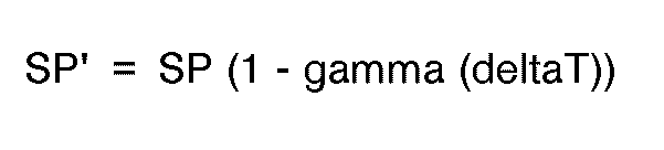 SP = the present preset reference,SP' = the recalculated reference,gamma = an ink specific parameter relating variation of viscosity of a given ink with the temperature of the ink, anddeltaT = the change in temperature since the previous determination of SP.
 - A method of drop marking, as in Claim 11, characterised by determining the ink specific parameter (gamma) according to:-
 m = the slope of the viscosity/temperature graph for a given ink over a region of interest,t = the flow time (time interval for a predetermined volume of ink to flow through an orifice, i.e. flow rate.), and» = viscosity.
Applications Claiming Priority (2)
| Application Number | Priority Date | Filing Date | Title |
|---|---|---|---|
| US07/169,627 US4860027A (en) | 1988-03-18 | 1988-03-18 | Ink drop control system with temperature compensation |
| US169627 | 1988-03-18 |
Publications (3)
| Publication Number | Publication Date |
|---|---|
| EP0333325A2 EP0333325A2 (en) | 1989-09-20 |
| EP0333325A3 EP0333325A3 (en) | 1991-04-03 |
| EP0333325B1 true EP0333325B1 (en) | 1995-07-19 |
Family
ID=22616491
Family Applications (1)
| Application Number | Title | Priority Date | Filing Date |
|---|---|---|---|
| EP89301458A Expired - Lifetime EP0333325B1 (en) | 1988-03-18 | 1989-02-15 | Ink drop control system with temperature compensation |
Country Status (5)
| Country | Link |
|---|---|
| US (1) | US4860027A (en) |
| EP (1) | EP0333325B1 (en) |
| JP (1) | JPH026143A (en) |
| CA (1) | CA1299702C (en) |
| DE (1) | DE68923469D1 (en) |
Families Citing this family (25)
| Publication number | Priority date | Publication date | Assignee | Title |
|---|---|---|---|---|
| US4999645A (en) * | 1990-01-29 | 1991-03-12 | Dell Marking Systems, Inc. | Electronically controlled marking |
| US5006503A (en) * | 1990-03-13 | 1991-04-09 | Eastman Kodak Company | Thermally-transferable fluorescent europium complexes |
| US5011816A (en) * | 1990-03-13 | 1991-04-30 | Eastman Kodak Company | Receiver for thermally-transferable fluorescent europium complexes |
| JPH04212751A (en) * | 1991-03-28 | 1992-08-04 | Matsushita Electric Ind Co Ltd | cassette tape recorder |
| US5418557A (en) * | 1991-10-03 | 1995-05-23 | Videojet Systems International, Inc. | Drop quality control system for jet printing |
| US5315316A (en) * | 1991-10-29 | 1994-05-24 | Hewlett-Packard Company | Method and apparatus for summing temperature changes to detect ink flow |
| US5396274A (en) * | 1992-05-20 | 1995-03-07 | Videojet Systems International, Inc. | Variable frequency ink jet printer |
| US5384160A (en) * | 1993-03-11 | 1995-01-24 | Frazzitta; Joseph | Method of coating a surface |
| US5623292A (en) * | 1993-12-17 | 1997-04-22 | Videojet Systems International, Inc. | Temperature controller for ink jet printing |
| JP3372821B2 (en) * | 1997-04-15 | 2003-02-04 | キヤノン株式会社 | Ink jet device, temperature estimation method and control method for ink jet head for the device |
| JP3782920B2 (en) * | 2000-03-28 | 2006-06-07 | セイコーインスツル株式会社 | Ink jet printer |
| JP3581306B2 (en) * | 2000-03-31 | 2004-10-27 | 株式会社イソワ | Ink viscosity measuring device, ink viscosity adjusting method and device therefor |
| US6382758B1 (en) | 2000-05-31 | 2002-05-07 | Lexmark International, Inc. | Printhead temperature monitoring system and method utilizing switched, multiple speed interrupts |
| FR2816546B1 (en) * | 2000-11-10 | 2003-08-29 | Leroux Gilles Sa | METHOD OF RELIEF MARKING OF A SUPPORTED OBJECT IN PLASTIC MATERIAL AND DEVICE IMPLEMENTING THE METHOD |
| US6883904B2 (en) * | 2002-04-24 | 2005-04-26 | Eastman Kodak Company | Apparatus and method for maintaining constant drop volumes in a continuous stream ink jet printer |
| US8210629B2 (en) * | 2009-05-20 | 2012-07-03 | Lexmark International, Inc. | Method for measuring ink flow rate in an inkjet printhead |
| MX377127B (en) | 2013-11-19 | 2025-03-07 | Archroma Ip Gmbh | INKJET PRINTING SYSTEM. |
| JP2016049738A (en) * | 2014-09-01 | 2016-04-11 | 東芝テック株式会社 | Ink circulation device |
| FR3025454B1 (en) | 2014-09-04 | 2016-12-23 | Markem-Imaje Holding | METHOD FOR MANAGING THE QUALITY OF THE INK OF AN INK JET PRINTER BASED ON TEMPERATURE. |
| CN110325368B (en) | 2017-04-06 | 2021-08-03 | 惠普发展公司,有限责任合伙企业 | Nozzle Features |
| EP3554842B1 (en) | 2017-04-06 | 2023-05-31 | Hewlett-Packard Development Company, L.P. | Fluid supply control |
| WO2020158759A1 (en) * | 2019-01-29 | 2020-08-06 | 株式会社日立産機システム | Inkjet recording device and method for controlling inkjet recording device |
| GB2584617B (en) * | 2019-05-21 | 2021-10-27 | Xaar Technology Ltd | Piezoelectric droplet deposition apparatus optimised for high viscosity fluids, and methods and control system therefor |
| US20230068297A1 (en) * | 2020-01-29 | 2023-03-02 | Hewlett-Packard Development Company, L.P. | Determining flow rates with thermal sensors |
| CN113204253B (en) * | 2021-04-16 | 2023-05-09 | 津药达仁堂集团股份有限公司第六中药厂 | Fuzzy control method and system for liquid level of dripping disc of dripping pill machine |
Family Cites Families (7)
| Publication number | Priority date | Publication date | Assignee | Title |
|---|---|---|---|---|
| JPS5670962A (en) * | 1979-11-16 | 1981-06-13 | Ricoh Co Ltd | Controlling method for ink density |
| JPS5981177A (en) * | 1982-06-17 | 1984-05-10 | Ricoh Co Ltd | Ink viscosity controller in ink jet printer |
| US4555712A (en) * | 1984-08-03 | 1985-11-26 | Videojet Systems International, Inc. | Ink drop velocity control system |
| JPS61121943A (en) * | 1984-11-19 | 1986-06-09 | Ricoh Co Ltd | Deflection control type ink jet recording apparatus |
| GB8530885D0 (en) * | 1985-12-16 | 1986-01-29 | Domino Printing Sciences Plc | Ink jet printing system |
| JPS632645A (en) * | 1986-06-23 | 1988-01-07 | Mitsubishi Electric Corp | Numerically controlled machine tool |
| JPS636604A (en) * | 1986-06-26 | 1988-01-12 | Mitsubishi Electric Corp | Numerical control system |
-
1988
- 1988-03-18 US US07/169,627 patent/US4860027A/en not_active Expired - Lifetime
-
1989
- 1989-02-15 EP EP89301458A patent/EP0333325B1/en not_active Expired - Lifetime
- 1989-02-15 DE DE68923469T patent/DE68923469D1/en not_active Expired - Lifetime
- 1989-02-24 CA CA000592022A patent/CA1299702C/en not_active Expired - Fee Related
- 1989-03-07 JP JP1053045A patent/JPH026143A/en active Pending
Also Published As
| Publication number | Publication date |
|---|---|
| DE68923469D1 (en) | 1995-08-24 |
| JPH026143A (en) | 1990-01-10 |
| US4860027A (en) | 1989-08-22 |
| CA1299702C (en) | 1992-04-28 |
| EP0333325A3 (en) | 1991-04-03 |
| EP0333325A2 (en) | 1989-09-20 |
Similar Documents
| Publication | Publication Date | Title |
|---|---|---|
| US4860027A (en) | Ink drop control system with temperature compensation | |
| CA1238238A (en) | Ink drop velocity control system | |
| US4714931A (en) | Ink jet printing system | |
| US4417256A (en) | Break-off uniformity maintenance | |
| US6561614B1 (en) | Ink system characteristic identification | |
| JPH0667621B2 (en) | Device for controlling and adjusting ink and processing the same in a continuous inkjet printer | |
| US5682183A (en) | Ink level sensor for an inkjet print cartridge | |
| US4575735A (en) | Droplet depositing viscosity line-pressure sensing control for fluid re-supply | |
| JPH05201025A (en) | Method and apparatus for controlling quality of drop for jet printing | |
| US4677845A (en) | Device for detecting viscosity of liquid | |
| EP0039772B1 (en) | Multinozzle ink jet printer and method of operating such a printer | |
| US5424766A (en) | Ink jet printer control system responsive to acoustical properties of ink | |
| US4905503A (en) | Method and device for measuring the viscosity of a fluid | |
| US4856322A (en) | Method and device for measuring the viscosity of an ink | |
| US4546648A (en) | Arrangement for measuring injection quantities | |
| EP0481797B1 (en) | Character height control for drop markers | |
| US5517216A (en) | Ink jet printer employing time of flight control system for ink jet printers | |
| JPS61265531A (en) | Liquid level detection device | |
| US10906324B2 (en) | Continuous inkjet printers | |
| JPS61266937A (en) | Liquid viscosity detection device | |
| US3416369A (en) | Fluid velocity measuring device | |
| JPS61266938A (en) | Liquid viscosity detection device | |
| CA1172059A (en) | Method and apparatus for electrically measuring fluid flow rates | |
| SU805218A1 (en) | Method of testing electro-thermal pulse pickups of non-electric values | |
| WO2019125463A1 (en) | Thermal conductivity determination of a print material |
Legal Events
| Date | Code | Title | Description |
|---|---|---|---|
| PUAI | Public reference made under article 153(3) epc to a published international application that has entered the european phase |
Free format text: ORIGINAL CODE: 0009012 |
|
| AK | Designated contracting states |
Kind code of ref document: A2 Designated state(s): CH DE FR GB IT LI NL |
|
| PUAL | Search report despatched |
Free format text: ORIGINAL CODE: 0009013 |
|
| AK | Designated contracting states |
Kind code of ref document: A3 Designated state(s): CH DE FR GB IT LI NL |
|
| 17P | Request for examination filed |
Effective date: 19910709 |
|
| 17Q | First examination report despatched |
Effective date: 19930301 |
|
| RAP1 | Party data changed (applicant data changed or rights of an application transferred) |
Owner name: VIDEOJET SYSTEMS INTERNATIONAL, INC. |
|
| GRAA | (expected) grant |
Free format text: ORIGINAL CODE: 0009210 |
|
| AK | Designated contracting states |
Kind code of ref document: B1 Designated state(s): CH DE FR GB IT LI NL |
|
| PG25 | Lapsed in a contracting state [announced via postgrant information from national office to epo] |
Ref country code: LI Effective date: 19950719 Ref country code: IT Free format text: LAPSE BECAUSE OF FAILURE TO SUBMIT A TRANSLATION OF THE DESCRIPTION OR TO PAY THE FEE WITHIN THE PRE;WARNING: LAPSES OF ITALIAN PATENTS WITH EFFECTIVE DATE BEFORE 2007 MAY HAVE OCCURRED AT ANY TIME BEFORE 2007. THE CORRECT EFFECTIVE DATE MAY BE DIFFERENT FROM THE ONE RECORDED.SCRIBED TIME-LIMIT Effective date: 19950719 Ref country code: CH Effective date: 19950719 Ref country code: FR Effective date: 19950719 Ref country code: NL Free format text: LAPSE BECAUSE OF FAILURE TO SUBMIT A TRANSLATION OF THE DESCRIPTION OR TO PAY THE FEE WITHIN THE PRESCRIBED TIME-LIMIT Effective date: 19950719 |
|
| REF | Corresponds to: |
Ref document number: 68923469 Country of ref document: DE Date of ref document: 19950824 |
|
| PG25 | Lapsed in a contracting state [announced via postgrant information from national office to epo] |
Ref country code: DE Effective date: 19951020 |
|
| EN | Fr: translation not filed | ||
| NLV1 | Nl: lapsed or annulled due to failure to fulfill the requirements of art. 29p and 29m of the patents act | ||
| PLBE | No opposition filed within time limit |
Free format text: ORIGINAL CODE: 0009261 |
|
| STAA | Information on the status of an ep patent application or granted ep patent |
Free format text: STATUS: NO OPPOSITION FILED WITHIN TIME LIMIT |
|
| 26N | No opposition filed | ||
| REG | Reference to a national code |
Ref country code: GB Ref legal event code: IF02 |
|
| PGFP | Annual fee paid to national office [announced via postgrant information from national office to epo] |
Ref country code: GB Payment date: 20020129 Year of fee payment: 14 |
|
| PG25 | Lapsed in a contracting state [announced via postgrant information from national office to epo] |
Ref country code: GB Free format text: LAPSE BECAUSE OF NON-PAYMENT OF DUE FEES Effective date: 20030215 |
|
| GBPC | Gb: european patent ceased through non-payment of renewal fee |