EP0333316B1 - Connecting box for multi-optical fiber cable - Google Patents
Connecting box for multi-optical fiber cable Download PDFInfo
- Publication number
- EP0333316B1 EP0333316B1 EP89301298A EP89301298A EP0333316B1 EP 0333316 B1 EP0333316 B1 EP 0333316B1 EP 89301298 A EP89301298 A EP 89301298A EP 89301298 A EP89301298 A EP 89301298A EP 0333316 B1 EP0333316 B1 EP 0333316B1
- Authority
- EP
- European Patent Office
- Prior art keywords
- trays
- adjacent
- side wall
- tray
- connecting box
- Prior art date
- Legal status (The legal status is an assumption and is not a legal conclusion. Google has not performed a legal analysis and makes no representation as to the accuracy of the status listed.)
- Expired - Lifetime
Links
- 239000013307 optical fiber Substances 0.000 title claims description 48
- 230000005540 biological transmission Effects 0.000 description 5
- 239000000835 fiber Substances 0.000 description 5
- 238000012423 maintenance Methods 0.000 description 2
- 238000000034 method Methods 0.000 description 2
- 230000002411 adverse Effects 0.000 description 1
- 230000015572 biosynthetic process Effects 0.000 description 1
- 238000010276 construction Methods 0.000 description 1
- 230000000717 retained effect Effects 0.000 description 1
Images


Classifications
-
- G—PHYSICS
- G02—OPTICS
- G02B—OPTICAL ELEMENTS, SYSTEMS OR APPARATUS
- G02B6/00—Light guides; Structural details of arrangements comprising light guides and other optical elements, e.g. couplings
- G02B6/44—Mechanical structures for providing tensile strength and external protection for fibres, e.g. optical transmission cables
- G02B6/4439—Auxiliary devices
- G02B6/4471—Terminating devices ; Cable clamps
-
- G—PHYSICS
- G02—OPTICS
- G02B—OPTICAL ELEMENTS, SYSTEMS OR APPARATUS
- G02B6/00—Light guides; Structural details of arrangements comprising light guides and other optical elements, e.g. couplings
- G02B6/44—Mechanical structures for providing tensile strength and external protection for fibres, e.g. optical transmission cables
- G02B6/4439—Auxiliary devices
- G02B6/444—Systems or boxes with surplus lengths
- G02B6/4441—Boxes
- G02B6/4446—Cable boxes, e.g. splicing boxes with two or more multi fibre cables
- G02B6/4447—Cable boxes, e.g. splicing boxes with two or more multi fibre cables with divided shells
-
- G—PHYSICS
- G02—OPTICS
- G02B—OPTICAL ELEMENTS, SYSTEMS OR APPARATUS
- G02B6/00—Light guides; Structural details of arrangements comprising light guides and other optical elements, e.g. couplings
- G02B6/44—Mechanical structures for providing tensile strength and external protection for fibres, e.g. optical transmission cables
- G02B6/4439—Auxiliary devices
- G02B6/444—Systems or boxes with surplus lengths
- G02B6/4452—Distribution frames
- G02B6/44526—Panels or rackmounts covering a whole width of the frame or rack
-
- G—PHYSICS
- G02—OPTICS
- G02B—OPTICAL ELEMENTS, SYSTEMS OR APPARATUS
- G02B6/00—Light guides; Structural details of arrangements comprising light guides and other optical elements, e.g. couplings
- G02B6/44—Mechanical structures for providing tensile strength and external protection for fibres, e.g. optical transmission cables
- G02B6/4439—Auxiliary devices
- G02B6/444—Systems or boxes with surplus lengths
- G02B6/44528—Patch-cords; Connector arrangements in the system or in the box
-
- G—PHYSICS
- G02—OPTICS
- G02B—OPTICAL ELEMENTS, SYSTEMS OR APPARATUS
- G02B6/00—Light guides; Structural details of arrangements comprising light guides and other optical elements, e.g. couplings
- G02B6/44—Mechanical structures for providing tensile strength and external protection for fibres, e.g. optical transmission cables
- G02B6/4439—Auxiliary devices
- G02B6/444—Systems or boxes with surplus lengths
- G02B6/4453—Cassettes
- G02B6/4454—Cassettes with splices
Definitions
- This invention relates to a connecting box for at least two multi-optical fiber cables. More particularly, this invention relates to an apparatus for connecting individual optic fibers of two or more fiber cable bundles without excess slack between the apparatus and the fiber cable bundles.
- a connecting box has been used to hold or contain surplus lengths of connecting end portions of optical fibers of the cables.
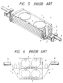
- One conventional connecting box under consideration shown in Fig. 5, comprises: a pair of opposed tray guides 2 and 2′ mounted on a connecting plate 3 and each having vertically spaced shelves, and a plurality of container trays 1 withdrawably supported respectively on the opposed shelves of the two tray guides 2 and 2′ in a stacked manner.
- the sheaths of the two cables A and A′ are first fastened respectively to the opposite ends of the connecting plate 3 by cable holders 4 and 4′. Then, the lowermost tray of the plurality of trays 1 is withdrawn from the tray guides 2 and 2′ transversely of the connecting plate 3, and two of the optical fibers a , extending from the sheath end of each of the cables A and A′, are introduced into the lowermost tray of the plurality of trays 1.
- the optical fibers a of the cable A are connected respectively to the optical fibers a of the cable A′ at their distal ends by means of connectors 5.
- a surplus length b of each optical fiber a is formed into a loop and is contained in the lowermost tray. Then, the lowermost tray is pushed back into the tray guides 2 and 2′. Thus, the connecting operation with respect to the lowermost tray 1 is completed. Then, the next lowermost tray of the plurality of trays 1, disposed immediately above the lowermost tray, is withdrawn and the same connecting operation is carried out. The operation continues for any number of optic fibers and any number of trays. In this manner, the connection between the other optical fibers a of the cables A and A′ is made according to the same procedure.
- Another disadvantage of the conventional connecting box is that once the tray 1 is pushed into the tray guides 2 and 2', the surplus lengths of optical fibers contained in the tray cannot easily be inspected.
- US '853 discloses a connecting box which comprises a plurality of trays which are hinged to a common support.
- the connecting box of WO '989 (which constitutes a state of the art under Article 54 (3) EPC) comprises a plurality of generally rectangular trays which are pivotally connected to each other by means of hinges, each tray including an opening provided generally centrally in the long side thereof through which optical fibers are arranged to be fed to the connecting box.
- a connecting box for connecting at least two multi-optical fiber cables together comprising a plurality of elongate container trays, each adapted to contain a surplus length of an end portion of at least one optical fiber of each of the at least two cables, said plurality of trays being stacked one upon another, each of the trays comprising a body which includes a generally flat, elongate base portion having opposite ends and opposite longitudinal edges, a pair of opposed side walls being formed respectively on the opposite longitudinal edges disposed in generally perpendicular relation to the base portion, each of the trays having a pair of receptive guide portions provided respectively at its opposite ends, adjacent to one of the longitudinal edges of the trays, each of the receptive guide portions being capable of receiving the at least one optical fiber of a respective one of the at least two cables, and adjacent trays being pivotally connected about an axis extending in the direction of said one longitudinal edge, characterized in that each of said trays includes at least one pair of upper and lower bearing portions formed on an outer
- each of the trays Since adjacent trays are hingedly connected together along one lateral side so as to be pivotally movable with respect to one another, the connecting portions of the optical fibers contained in each of the trays are easily accessible, which facilitates the maintenance and repair of these connecting portions.
- the portions of the optical fibers extending outwardly from each receptive guide portion are substantially unchanged in length; that is, kept almost constant, even when one or more of the trays are pivotally moved, since the axis of this pivotal movement is disposed along and close to the one lateral side of the tray adjacent to which the pair of receptive guide portions are provided.
- the portions of the optical fibers extending outwardly from the receptive guide portion are not subjected to slack and hence are positively prevented from being formed into an arcuate shape or a circular shape having a small radius of curvature. Therefore, the transmission characteristics of the optical fibers will not be affected by such slack in the fibers.
- a connecting box 10 comprises a plurality of container trays 11 of an identical shape.
- Each tray 11 includes a container-like body with an open top.
- the tray body is made of a rigid sheet or plate and has a flat base plate or portion 11a of a generally rectangular shape having opposite rounded ends, a pair of opposed side walls 12 and 12' formed on and extending along opposite longitudinal side edges of the base portion 11a, respectively, in perpendicular relation to the base portion 11a, and a pair of opposed, arcuate end walls 13 and 13' formed on the opposite rounded ends of the base portion 11a and disposed in perpendicular relation to the base portion 11a.
- a receptive guide portion 14, of a channel-shaped cross-section for receiving optical fibers, is formed at one side of each of the end walls 13 and 13'.
- the receptive guide portion 14 is defined by an end portion 12a of the side wall 12, an inner wall 14a disposed in parallel opposed relation to the end portion 12a, and a bottom wall 14b interconnecting the end portion 12a and the inner wall 14a at their lower ends and disposed in coplanar relation to the base portion 11a.
- Two pairs of upper and lower bearings 15 and 16 are formed on an outer surface of the side wall 12 of each tray 11.
- the two pairs that is, the right-hand and left-hand pairs (Figs. 1 and 2) are spaced from each other in the direction of the length of the side wall 12.
- Each upper bearing 15 is disposed adjacent to the upper edge of the side wall 12 while each lower bearing 16 is disposed adjacent to the lower edge of the side wall 12.
- the right-hand (left-hand) upper bearing 15 of each tray 11 is disposed in line with the right-hand (left-hand) lower bearing 15 of its upper adjacent tray 11 in contiguous relation thereto, with a bearing aperture 17 of the upper bearing 15 aligned with a bearing aperture 18 of the lower bearing 16.
- a pivot or hinge pin 19 is passed through the thus aligned apertures 17 and 18 of the upper and lower bearings 15 and 16 of the two adjacent trays 11 to hingedly connect them together.
- the two adjacent trays 11 can be pivotally moved relative to each other about the two pivot pins 19 passing through the aligned right-hand bearings 15 and 16 and the aligned left-hand bearings 15 and 16, respectively.
- An end cap 19a is detachably fitted on the distal end of the pivot pin 19 to prevent the pin 19 from being disengaged from the aligned upper and lower bearings 15 and 16. Removing the end cap 19a allows the pivot pin 19 to be disengaged or withdrawn from the aligned upper and lower bearings 15 and 16.
- a pair of stop lugs 20 are formed on the outer surface of the side wall 12 of each tray 11 immediately adjacent to its upper edge and spaced from each other along the length of the side wall 12.
- a pin-like connecting projection 21 is formed on an outer surface of the side wall 12′ of each tray 11. In the stacked condition of the trays 11, these connecting projections 21 on the trays 11 are disposed in registry with one another in the direction of the thickness of the stack of trays 11.
- the trays 11 are joined together in a stacked condition against pivotal movement by a connecting band or strip 22 having a longitudinal slit releasably fitted on the connecting projections 21 disposed in registry with one another.
- a pair of curvature guide portions 23 are formed on an upper surface of the base portion 11a of each tray 11 and spaced from each other along the length of the base portion 11a.
- a connector holder portion 24 for holding connectors 5 is also formed on the upper surface of the base portion 11a and disposed between the pair of curvature guide portions 23 adjacent to the side wall 12.
- one tray 11 is fixedly secured to an elongated connecting plate 3 by suitable fastening means such as screws, so that this tray 11 constitutes the lowermost tray.
- Sheaths of two multi-optical fiber cables A and A′, to be connected together, are fastened respectively to the opposite ends of the connecting plate 3 by cable holders 4.
- the optical fibers a of each of the cables A and A′ have exposed end portions extending from the sheath end held by the cable holder 4.
- the end portions of two of the optical fibers a of each of the cables A and A′ are introduced into the lowermost tray 11 through a respective one of the receptive guide portions 14.
- Each of the thus introduced two optical fibers a of the cable A and a respective one of the thus introduced two optical fibers a of the cable A′ are connected together at their ends through the connector 5.
- the connector 5 is retained in position by the connector holder 24.
- the other trays 11 are pivotally connected one after another to provide the stack of trays 11.
- the number of the trays 11 is five, a desired number of trays 11 can be used.
- the connecting band 22 is fitted on the connecting projections 21 on the trays 11 disposed in the stacked condition, thereby fixing the trays 11 with respect to the connecting plate 3.
- the connecting portions of the optical fibers a contained in each of the trays 11 are easily accessible, which facilitates the maintenance and repair of these connecting portions.
- the portions c of the optical fibers a extending between the cable holder 4 and the receptive guide portion 14 are kept almost constant even when the tray 11 is pivotally moved away from and toward its adjacent tray.
- the portions c are not subjected to slack, which positively prevents the portions c from being formed into an arcuate shape or a loopshape having a small radius of curvature. Therefore, the transmission characteristics of the optical fibers a will not be affected by arcuate shapes caused by transmission line slack.
Landscapes
- Physics & Mathematics (AREA)
- General Physics & Mathematics (AREA)
- Optics & Photonics (AREA)
- Mechanical Coupling Of Light Guides (AREA)
- Light Guides In General And Applications Therefor (AREA)
Description
- This invention relates to a connecting box for at least two multi-optical fiber cables. More particularly, this invention relates to an apparatus for connecting individual optic fibers of two or more fiber cable bundles without excess slack between the apparatus and the fiber cable bundles.
- Conventionally, in the case of the branching, the leading-in, the connecting or the like of multi-optical fiber cables, comprising a plurality of optical fibers, a connecting box has been used to hold or contain surplus lengths of connecting end portions of optical fibers of the cables.
- One conventional connecting box under consideration, shown in Fig. 5, comprises: a pair of
opposed tray guides plate 3 and each having vertically spaced shelves, and a plurality ofcontainer trays 1 withdrawably supported respectively on the opposed shelves of the twotray guides - For connecting two multi-optical fiber cables A and A′ together using this conventional connecting box, the sheaths of the two cables A and A′ are first fastened respectively to the opposite ends of the connecting
plate 3 bycable holders trays 1 is withdrawn from thetray guides connecting plate 3, and two of the optical fibers a, extending from the sheath end of each of the cables A and A′, are introduced into the lowermost tray of the plurality oftrays 1. The optical fibers a of the cable A are connected respectively to the optical fibers a of the cable A′ at their distal ends by means ofconnectors 5. A surplus length b of each optical fiber a is formed into a loop and is contained in the lowermost tray. Then, the lowermost tray is pushed back into thetray guides lowermost tray 1 is completed. Then, the next lowermost tray of the plurality oftrays 1, disposed immediately above the lowermost tray, is withdrawn and the same connecting operation is carried out. The operation continues for any number of optic fibers and any number of trays. In this manner, the connection between the other optical fibers a of the cables A and A′ is made according to the same procedure. - With this construction, however, when the
tray 1 is pushed into thetray guides tray 1, that portion c of each optical fiber a extending between thecable holder 4 and the end oftray 1 becomes loosened or slacked, so that the portion c tends to be formed into a loop having an arcuate portion of a small radius of curvature, as shown in Fig. 6. - The presence of such an arcuate portion of a small radius of curvature in the optical fiber will adversely affect its transmission characteristics.
- Another disadvantage of the conventional connecting box is that once the
tray 1 is pushed into thetray guides 2 and 2', the surplus lengths of optical fibers contained in the tray cannot easily be inspected. - Further connecting boxes are disclosed in US 4266853 and WO89/05989. US '853 discloses a connecting box which comprises a plurality of trays which are hinged to a common support. The connecting box of WO '989 (which constitutes a state of the art under Article 54 (3) EPC) comprises a plurality of generally rectangular trays which are pivotally connected to each other by means of hinges, each tray including an opening provided generally centrally in the long side thereof through which optical fibers are arranged to be fed to the connecting box.
- It is therefore an object of this invention to provide a connecting box for at least two multi-optical fiber cables which will not affect the transmission characteristics of the optical fibers and allows easy access to the optical fibers contained in the container trays.
- According to the present invention there is provided a connecting box for connecting at least two multi-optical fiber cables together, comprising a plurality of elongate container trays, each adapted to contain a surplus length of an end portion of at least one optical fiber of each of the at least two cables, said plurality of trays being stacked one upon another, each of the trays comprising a body which includes a generally flat, elongate base portion having opposite ends and opposite longitudinal edges, a pair of opposed side walls being formed respectively on the opposite longitudinal edges disposed in generally perpendicular relation to the base portion, each of the trays having a pair of receptive guide portions provided respectively at its opposite ends, adjacent to one of the longitudinal edges of the trays, each of the receptive guide portions being capable of receiving the at least one optical fiber of a respective one of the at least two cables, and adjacent trays being pivotally connected about an axis extending in the direction of said one longitudinal edge, characterized in that each of said trays includes at least one pair of upper and lower bearing portions formed on an outer surface of one of said side walls, said upper bearing portion being disposed adjacent to an upper edge of said one side wall remote from said base portion while said lower bearing portion is disposed adjacent to a lower edge of said one side wall closer to said base portion, said upper bearing portion of a lower one of adjacent trays being disposed in alignment with said lower bearing portion of an upper one of said adjacent trays, and there being provided a pivot pin releasably fitted in the thus aligned upper and lower bearings of said adjacent trays to pivotally connect them together so that adjacent trays can be pivotally moved with respect to each other about said pivot pin which extends along the length of said one side wall.
- Since adjacent trays are hingedly connected together along one lateral side so as to be pivotally movable with respect to one another, the connecting portions of the optical fibers contained in each of the trays are easily accessible, which facilitates the maintenance and repair of these connecting portions. In addition, the portions of the optical fibers extending outwardly from each receptive guide portion are substantially unchanged in length; that is, kept almost constant, even when one or more of the trays are pivotally moved, since the axis of this pivotal movement is disposed along and close to the one lateral side of the tray adjacent to which the pair of receptive guide portions are provided. Therefore, the portions of the optical fibers extending outwardly from the receptive guide portion are not subjected to slack and hence are positively prevented from being formed into an arcuate shape or a circular shape having a small radius of curvature. Therefore, the transmission characteristics of the optical fibers will not be affected by such slack in the fibers.
- In accordance with these and other objects which will become apparent, the present invention will be described with particular reference to the accompanying drawings.
- The invention will further be described by way of example with reference to the accompanying drawings, in which:
- Fig. 1 is a perspective view of a connecting box provided in accordance with an embodiment of the present invention, which is disposed between two multi-optical fiber cables to connect them together.
- Fig. 2 is a top plan view of the connecting box;
- Fig. 3 is an end view of the connecting box, with an
uppermost container tray 11 shown as held in its open position; - Fig. 4 is a fragmentary, enlarged perspective view of the trays of the connecting box;
- Fig. 5 is a perspective view of a connecting box provided in accordance with the prior art; and
- Fig. 6 is a top plan view of the connecting box of Fig. 5, with one container tray shown in a withdrawn condition.
- The invention will now be described with reference to Figs. 1 to 4.
- A connecting
box 10 according to the present invention comprises a plurality ofcontainer trays 11 of an identical shape. Eachtray 11 includes a container-like body with an open top. The tray body is made of a rigid sheet or plate and has a flat base plate orportion 11a of a generally rectangular shape having opposite rounded ends, a pair ofopposed side walls 12 and 12' formed on and extending along opposite longitudinal side edges of thebase portion 11a, respectively, in perpendicular relation to thebase portion 11a, and a pair of opposed,arcuate end walls base portion 11a and disposed in perpendicular relation to thebase portion 11a. Areceptive guide portion 14, of a channel-shaped cross-section for receiving optical fibers, is formed at one side of each of theend walls receptive guide portion 14 is defined by anend portion 12a of theside wall 12, an inner wall 14a disposed in parallel opposed relation to theend portion 12a, and a bottom wall 14b interconnecting theend portion 12a and the inner wall 14a at their lower ends and disposed in coplanar relation to thebase portion 11a. - Two pairs of upper and
lower bearings side wall 12 of eachtray 11. The two pairs, that is, the right-hand and left-hand pairs (Figs. 1 and 2) are spaced from each other in the direction of the length of theside wall 12. Eachupper bearing 15 is disposed adjacent to the upper edge of theside wall 12 while eachlower bearing 16 is disposed adjacent to the lower edge of theside wall 12. When the plurality oftrays 11 are stacked one upon another in position, the right-hand (left-hand) upper bearing 15 of eachtray 11 is disposed in line with the right-hand (left-hand) lower bearing 15 of its upperadjacent tray 11 in contiguous relation thereto, with abearing aperture 17 of the upper bearing 15 aligned with abearing aperture 18 of thelower bearing 16. A pivot orhinge pin 19 is passed through the thus alignedapertures lower bearings adjacent trays 11 to hingedly connect them together. In this manner, the twoadjacent trays 11 can be pivotally moved relative to each other about the twopivot pins 19 passing through the aligned right-hand bearings hand bearings end cap 19a is detachably fitted on the distal end of thepivot pin 19 to prevent thepin 19 from being disengaged from the aligned upper andlower bearings end cap 19a allows thepivot pin 19 to be disengaged or withdrawn from the aligned upper andlower bearings - A pair of
stop lugs 20 are formed on the outer surface of theside wall 12 of eachtray 11 immediately adjacent to its upper edge and spaced from each other along the length of theside wall 12. When eachtray 11 is pivotally moved in its opening direction, that is, away from its lower adjacent tray, about thepivot pins 19, theside wall 12 of thisupper tray 11 is brought into engagement with thestop lugs 20 of its loweradjacent tray 11 so as to prevent a further pivotal movement of theupper tray 11. Thus, theupper tray 11 may be held by thestop lugs 20 in its open condition at a predetermined angle, for example, of 100 degrees, as shown in Fig. 3. - A pin-like connecting
projection 21 is formed on an outer surface of theside wall 12′ of eachtray 11. In the stacked condition of thetrays 11, these connectingprojections 21 on thetrays 11 are disposed in registry with one another in the direction of the thickness of the stack oftrays 11. Thetrays 11 are joined together in a stacked condition against pivotal movement by a connecting band orstrip 22 having a longitudinal slit releasably fitted on the connectingprojections 21 disposed in registry with one another. - A pair of
curvature guide portions 23 are formed on an upper surface of thebase portion 11a of eachtray 11 and spaced from each other along the length of thebase portion 11a. Aconnector holder portion 24 forholding connectors 5 is also formed on the upper surface of thebase portion 11a and disposed between the pair ofcurvature guide portions 23 adjacent to theside wall 12. - For using the connecting
box 10, first, onetray 11 is fixedly secured to an elongated connectingplate 3 by suitable fastening means such as screws, so that thistray 11 constitutes the lowermost tray. Sheaths of two multi-optical fiber cables A and A′, to be connected together, are fastened respectively to the opposite ends of the connectingplate 3 bycable holders 4. The optical fibers a of each of the cables A and A′ have exposed end portions extending from the sheath end held by thecable holder 4. - Then, the end portions of two of the optical fibers a of each of the cables A and A′ are introduced into the
lowermost tray 11 through a respective one of thereceptive guide portions 14. Each of the thus introduced two optical fibers a of the cable A and a respective one of the thus introduced two optical fibers a of the cable A′ are connected together at their ends through theconnector 5. Theconnector 5 is retained in position by theconnector holder 24. - Then, the surplus lengths b of the end portions of the two optical fibers a of each of the cables A and A′ are formed into a loop around the
curvature guide 23 within thelowermost tray 11. Thus, the two optical fibers of each of the cables A and A′ are contained within thelowermost tray 11. - Then, another
tray 11 is stacked on thelowermost tray 11, with theupper bearings 15 of thelowermost tray 11 aligned with thelower bearings 16 of theupper tray 11, respectively, and thepivot pin 19 is passed through the alignedbearing apertures lower bearings trays 11 together. Then, another two optical fibers a of each of the cables A and A′ are contained within theupper tray 11 adjacent to thelowermost tray 11, as described above for thelowermost tray 11. - According to the same procedure, the
other trays 11 are pivotally connected one after another to provide the stack oftrays 11. In this embodiment, although the number of thetrays 11 is five, a desired number oftrays 11 can be used. - After the connection between the cables A and A′ is completed, the connecting
band 22 is fitted on the connectingprojections 21 on thetrays 11 disposed in the stacked condition, thereby fixing thetrays 11 with respect to the connectingplate 3. - When it is desired to readjust the connecting portions of the optical fibers a contained in any of the stack of
trays 11 after the connection between the cables A and A′ is completed, or when it is required to maintain or repair the connecting portions of the optical fibers a a prescribed period of time after the cables A and A′ are connected together, such operation can be easily carried out by pivotally moving thosetrays 11, disposed above thetray 11 to be checked, in unison in a direction away from the tray tobe checked. At this time, the portions c of the optical fibers a extending between eachcable holder 4 and thereceptive guide portion 14 disposed closer thereto are substantially unchanged in length even when one or more of thetrays 11 are pivotally moved in its opening direction. Therefore, the portions c of the optical fibers a are not subjected to slack when thetray 11 is returned to its closed position after the required operation is finished. - As described above, since
adjacent trays 11 are hingedly connected together at their one sides so as to be pivotally movable with respect to one another, the connecting portions of the optical fibers a contained in each of thetrays 11 are easily accessible, which facilitates the maintenance and repair of these connecting portions. In addition, the portions c of the optical fibers a extending between thecable holder 4 and thereceptive guide portion 14 are kept almost constant even when thetray 11 is pivotally moved away from and toward its adjacent tray. The portions c are not subjected to slack, which positively prevents the portions c from being formed into an arcuate shape or a loopshape having a small radius of curvature. Therefore, the transmission characteristics of the optical fibers a will not be affected by arcuate shapes caused by transmission line slack.
Claims (6)
- A connecting box for connecting at least two multi-optical fiber cables (A, A') together, comprising a plurality of elongate container trays (11), each adapted to contain a surplus length of an end portion of at least one optical fiber of each of the at least two cables, said plurality of trays (11) being stacked one upon another, each of the trays comprising a body which includes a generally flat, elongate base portion (11a) having opposite ends and opposite longitudinal edges, a pair of opposed side walls (12, 12') being formed respectively on the opposite longitudinal edges disposed in generally perpendicular relation to the base portion (11a), each of the trays (11) having a pair of receptive guide portions (14) provided respectively at its opposite ends, adjacent to one (12) of the longitudinal edges of the trays (11), each of the receptive guide portions (14) being capable of receiving the at least one optical fiber of a respective one of the at least two cables, and adjacent trays (11) being pivotally connected other about an axis extending in the direction of said one longitudinal edge, characterized in that each of said trays (11) includes at least one pair of upper and lower bearing portions (15, 16) formed on an outer surface of one (12) of said side walls (12, 12'), said upper bearing portion (15) being disposed adjacent to an upper edge of said one side wall (12) remote from said base portion (11a) while said lower bearing portion (16) is disposed adjacent to a lower edge of said one side wall (12) closer to said base portion (11a), said upper bearing portion (15) of a lower one of adjacent trays (11) being disposed in alignment with said lower bearing portion (16) of an upper one of said adjacent trays (11), and there being provided a pivot pin (19) releasably fitted in the thus aligned upper and lower bearings (15, 16) of said adjacent trays (11) to pivotally connect them together so that adjacent trays (11) can be pivotally moved with respect to each other about said pivot pin (19) which extends along the length of said one side wall (12).
- A connecting box as claimed in Claim 1, characterized in that each of said trays is provided with two pairs of said upper and lower bearing members (15, 16), said two pairs being spaced from each other along the length of said one side wall (12) of each of said trays (11).
- A connecting box as claimed in Claim 1 or Claim 2, characterized by means (21, 22) for releasably joining said plurality of trays together in a stacked condition against pivotal movement.
- A connecting box as claimed in Claim 3, characterized in that said releasably joining means comprises a connecting pin (21) formed on an outer surface of the other side wall (12') of each of said trays (11), and a connecting band (22) having a longitudinal slit therein, said pins (21) on said trays (11) being disposed in registry with each other in a direction of the width of said stack of trays (11), and said slit being releasably fitted in said connecting pins (21) disposed in registry with one another so as to join said trays (11) together against pivotal movement.
- A connecting box as claimed in any one of the preceding claims, characterized by means (20) for preventing each of said trays (11) from pivotally moving about said axis beyond a predetermined angle.
- A connecting box as claimed in any one of the preceding claims, characterized by a stop lug (20) formed on the outer surface of said one side wall (12) of each of said trays (11), adjacent to the upper edge of said one side wall (12), said stop lug (20) on a lower one of adjacent trays (11) being engageable with said one side wall (12) of an upper one when said upper tray (11) is pivotally moved away from said lower tray (11) about said pivot pin (19) through a predetermined angle, thereby limiting pivotal movement.
Applications Claiming Priority (2)
| Application Number | Priority Date | Filing Date | Title |
|---|---|---|---|
| JP62295/88 | 1988-03-15 | ||
| JP63062295A JPH063487B2 (en) | 1988-03-15 | 1988-03-15 | Multi-fiber optical fiber cable junction box |
Publications (3)
| Publication Number | Publication Date |
|---|---|
| EP0333316A2 EP0333316A2 (en) | 1989-09-20 |
| EP0333316A3 EP0333316A3 (en) | 1990-09-12 |
| EP0333316B1 true EP0333316B1 (en) | 1993-12-22 |
Family
ID=13195982
Family Applications (1)
| Application Number | Title | Priority Date | Filing Date |
|---|---|---|---|
| EP89301298A Expired - Lifetime EP0333316B1 (en) | 1988-03-15 | 1989-02-10 | Connecting box for multi-optical fiber cable |
Country Status (3)
| Country | Link |
|---|---|
| US (1) | US4911521A (en) |
| EP (1) | EP0333316B1 (en) |
| JP (1) | JPH063487B2 (en) |
Families Citing this family (68)
| Publication number | Priority date | Publication date | Assignee | Title |
|---|---|---|---|---|
| US5071211A (en) * | 1988-12-20 | 1991-12-10 | Northern Telecom Limited | Connector holders and distribution frame and connector holder assemblies for optical cable |
| GB8908399D0 (en) * | 1989-04-13 | 1989-06-01 | British Telecomm | Optical fibre back plane |
| JP2825277B2 (en) * | 1989-06-23 | 1998-11-18 | 古河電気工業株式会社 | Closure for optical cable |
| US5074635A (en) * | 1990-05-21 | 1991-12-24 | Minnesota Mining And Manufacturing Company | Splice tray and method |
| DE4106171A1 (en) * | 1991-02-27 | 1992-09-03 | Siemens Ag | CASSETTE AND CASSETTE BLOCK FOR LIGHTWAVE GUIDE |
| EP0501336B1 (en) * | 1991-02-27 | 1996-06-05 | Siemens Aktiengesellschaft | Separating housing for lightwave guides |
| CA2050356C (en) * | 1991-08-30 | 2003-02-11 | George Debortoli | Optical fiber storage |
| FR2687743B1 (en) * | 1992-02-21 | 1995-06-16 | Mars Actel | SET OF STACKED AND ARTICULATED MODULES. |
| GB2281408B (en) * | 1992-03-25 | 1995-11-22 | Fibernet Research Pty Ltd | Housing for optical fibres |
| DE59308529D1 (en) * | 1992-07-17 | 1998-06-18 | Rxs Schrumpftech Garnituren | Arrangement for storing splice cassettes for optical fibers within a cable sleeve |
| JP2587388Y2 (en) * | 1992-12-08 | 1998-12-16 | 株式会社サンコーシヤ | Optical fiber cable storage case |
| CH688112A5 (en) * | 1993-03-23 | 1997-05-15 | Reichle & De Massari Fa | Cartridge assembly for connecting and branching of optical waveguides of the telecommunications and data communications. |
| GB9306854D0 (en) * | 1993-04-01 | 1993-05-26 | Raychem Sa Nv | Optical fibre organizer |
| US5479553A (en) * | 1993-04-19 | 1995-12-26 | Raychem Corporation | Fiber optic splice closure |
| US5375185A (en) * | 1993-04-30 | 1994-12-20 | Keptel, Inc. | Apparatus for storing and organizing spliced optical fibers |
| DE9307136U1 (en) * | 1993-05-11 | 1993-07-15 | Stewing Kunststoffbetrieb GmbH, 4270 Dorsten | Cassette holder |
| US5446822A (en) * | 1993-05-28 | 1995-08-29 | Minnesota Mining And Manufacturing Company | Connector clip for fiber optic housing |
| US5363467A (en) * | 1993-05-28 | 1994-11-08 | Minnesota Mining And Manufacturing Company | Compact fiber optic housing |
| GB9314161D0 (en) * | 1993-07-08 | 1993-08-18 | Rose Walter Gmbh & Co Kg | A multi-filament splice enclosure |
| GB9318654D0 (en) * | 1993-09-08 | 1993-10-27 | Raychem Sa Nv | Optical fibre organizer |
| GB9318602D0 (en) * | 1993-09-08 | 1993-10-27 | Raychem Sa Nv | Optical fibre organizer |
| GB9318632D0 (en) * | 1993-09-08 | 1993-10-27 | Raychem Sa Nv | Optical fibre organizer |
| GB9400626D0 (en) * | 1994-01-14 | 1994-03-09 | Augat Limited | Management of optical fibres |
| GB9405535D0 (en) * | 1994-03-21 | 1994-05-04 | Raychem Sa Nv | Splice organizing apparatus |
| NZ303594A (en) * | 1995-03-31 | 1999-01-28 | Minnesota Mining & Mfg | Optical fibre splice tray arrangement |
| FR2733843B1 (en) * | 1995-05-03 | 1997-05-30 | Alcatel Submarcom | ORGANIZER DEVICE FOR CONNECTING FIBER OPTIC CABLES AND JUNCTION BOX FOR OPTICAL CABLES |
| US5613029A (en) * | 1995-05-10 | 1997-03-18 | Lucent Technologies Inc. | Fiber optic splice tray hinge adapter |
| US5530786A (en) * | 1995-05-30 | 1996-06-25 | The Whitaker Corporation | Holding for optical fiber splice couplings |
| US5566268A (en) * | 1995-05-30 | 1996-10-15 | The Whitaker Corporation | Strain relieving holder for optical fiber cable |
| US5566269A (en) * | 1995-05-30 | 1996-10-15 | The Whitaker Corporation | Strain relieving holder for optical fiber cable |
| US5835657A (en) * | 1995-12-08 | 1998-11-10 | Psi Telecommunications, Inc. | Fiber optic splice tray |
| GB9607609D0 (en) * | 1996-04-12 | 1996-06-12 | Telephone Cables Ltd | Cable treatment |
| DE69713544T2 (en) * | 1996-04-12 | 2003-02-20 | Telephone Cables Ltd., Dagenham | Arrangement of an optical fiber |
| US5825960A (en) * | 1996-04-30 | 1998-10-20 | The Whitaker Corporation | Fiber optic management system |
| JP2877080B2 (en) * | 1996-06-21 | 1999-03-31 | 日本電気株式会社 | Optical fiber extra length processing case |
| FR2782171B1 (en) * | 1998-08-04 | 2001-11-30 | Pouyet Sa | FIBER OPTIC CABLES CONNECTION DEVICE |
| GB2343261B (en) * | 1998-10-29 | 2002-12-11 | Bowthorpe Plc | Optical fibre storage apparatus with movable stacks |
| US6249633B1 (en) * | 1998-11-12 | 2001-06-19 | Wittmeier, Ii David Arthur | Fiber optic splice closure including side pivoting slack storage holder and associated methods |
| GB9907406D0 (en) * | 1999-03-31 | 1999-05-26 | Raychem Sa Nv | An optical fibre management system |
| FR2793564B1 (en) * | 1999-05-11 | 2001-07-13 | Rxs Morel Accessoires De Cable | STACK OF CASSETTES THAT CAN OPEN FROM TWO SIDES |
| DE19956067A1 (en) | 1999-11-22 | 2001-05-23 | Rxs Kabelgarnituren Gmbh & Co | Cassette for accommodating optical fibres, surplus lengths, splices, etc., has differently shaped splice holders for various types of splice protection elements, and add-on elements for adapting to required use |
| US6496640B1 (en) * | 1999-12-16 | 2002-12-17 | Corning Cable Systems Llc | Splice closure with removable and pivotable splice trays, and associated methods |
| US6781724B1 (en) * | 2000-06-13 | 2004-08-24 | Eastman Kodak Company | Image processing and manipulation system |
| US6944387B2 (en) | 2001-04-30 | 2005-09-13 | Telect, Inc. | Fiber optic connector tray system |
| US6674952B2 (en) | 2001-04-30 | 2004-01-06 | Telect, Inc. | Fiber optic cable bend radius protection system |
| JP3797540B2 (en) * | 2001-05-14 | 2006-07-19 | 大日本スクリーン製造株式会社 | Optical fiber extra length storage device |
| JP3964638B2 (en) * | 2001-08-22 | 2007-08-22 | 富士通株式会社 | Shelf equipment |
| US6934451B2 (en) * | 2003-06-28 | 2005-08-23 | General Dynamics Advanced Information Systems, Inc. | Mount for use in optical fiber hydrophone array |
| US6879545B2 (en) * | 2003-06-28 | 2005-04-12 | General Dynamics Advanced Information Systems, Inc. | Woven fiber protection cable assembly for use in optical fiber hydrophone array |
| US6904222B2 (en) * | 2003-06-28 | 2005-06-07 | General Dynamics Advanced Information Systems, Inc. | Optical fiber splice protection apparatus for use in optical fiber hydrophone array |
| US7027695B2 (en) * | 2003-06-28 | 2006-04-11 | General Dynamics Advanced Information Systems, Inc. | Fiber transition segment for use in optical fiber hydrophone array |
| US6870997B2 (en) * | 2003-06-28 | 2005-03-22 | General Dynamics Advanced Information Systems, Inc. | Fiber splice tray for use in optical fiber hydrophone array |
| US6865334B2 (en) * | 2003-06-28 | 2005-03-08 | General Dynamics Advanced Information Systems, Inc. | Termination assembly for use in optical fiber hydrophone array |
| US7000863B2 (en) * | 2003-09-29 | 2006-02-21 | Lucent Technologies Inc. | Method and apparatus for operational low-stress optical fiber storage |
| JP4537081B2 (en) * | 2004-01-27 | 2010-09-01 | 神保電器株式会社 | OPTICAL FIBER PREVIOUS WIRING METHOD FOR GROUP RESIDENTS AND PREPARED WIRING OPTICAL CONNECTION CABINET FOR GROUP RESIDENT |
| US7072559B2 (en) * | 2004-07-09 | 2006-07-04 | Tyco Telecommunications (Us) Inc. | Multiple hinged tray cable connecting joint and method of using same |
| FR2898417B1 (en) * | 2006-03-10 | 2008-09-19 | Ictl Soc Par Actions Simplifie | LOADING BOX OF WIRED ELEMENTS |
| FR2917186A1 (en) | 2007-06-11 | 2008-12-12 | Free Soc Par Actions Simplifie | RECORDING HOUSING FOR OPTICAL FIBERS |
| JP4889590B2 (en) * | 2007-08-01 | 2012-03-07 | 河村電器産業株式会社 | Fusing tray hinge structure |
| GB0803802D0 (en) * | 2008-02-29 | 2008-04-09 | Tyco Electronics Raychem Nv | Optical fibre organiser |
| US8009954B2 (en) * | 2008-04-21 | 2011-08-30 | Adc Telecommunications, Inc. | Fiber optic splice tray |
| US8086084B2 (en) * | 2008-09-09 | 2011-12-27 | Adc Telecommunications, Inc. | Fiber optic splice tray |
| USD626122S1 (en) | 2009-07-07 | 2010-10-26 | Commscope, Inc. Of North Carolina | Stackable optical module enclosure |
| EP3239753B1 (en) * | 2011-02-17 | 2023-11-15 | Bison Patent Licensing, LLC | Optical fiber organizer |
| EP3583456A1 (en) * | 2017-02-15 | 2019-12-25 | CommScope Connectivity Belgium BVBA | Modular telecommunications enclosures |
| WO2019212887A1 (en) | 2018-05-01 | 2019-11-07 | Commscope Technologies Llc | Tray tower with position indexing trays |
| WO2020005998A1 (en) * | 2018-06-28 | 2020-01-02 | Nlight, Inc. | Fiber management cartridge |
| US12210203B2 (en) | 2019-03-29 | 2025-01-28 | Commscope Technologies Llc | Tray hinge interface system with opposing recessed surfaces recessed toward the pivot axis |
Citations (1)
| Publication number | Priority date | Publication date | Assignee | Title |
|---|---|---|---|---|
| WO1989005989A1 (en) * | 1987-12-23 | 1989-06-29 | British Telecommunications Public Limited Company | Mounting assembly for optical equipment |
Family Cites Families (13)
| Publication number | Priority date | Publication date | Assignee | Title |
|---|---|---|---|---|
| JPS51152712U (en) * | 1975-05-30 | 1976-12-06 | ||
| US4266853A (en) * | 1979-03-12 | 1981-05-12 | Northern Telecom Limited | Device for organizing optical fibers and the like |
| JPS59102208A (en) * | 1982-12-06 | 1984-06-13 | Nippon Telegr & Teleph Corp <Ntt> | Containing structure of optical fiber core wire connecting part |
| JPS59101207U (en) * | 1982-12-27 | 1984-07-07 | 古河電気工業株式会社 | Multi-fiber optical connection storage box |
| FR2556895B1 (en) * | 1983-12-20 | 1986-12-19 | Lignes Telegraph Telephon | DEVICE FOR CONNECTING CABLES, PARTICULARLY WITH OPTICAL FIBERS |
| FR2559916B1 (en) * | 1984-02-21 | 1989-02-24 | Constr Telephoniques | METHOD USED IN THE CONNECTION OF OPTICAL FIBERS TO CONSTITUTE AND STORE A RESERVE FIBER SECTION AND DEVICE RELATING THERETO |
| EP0159857B1 (en) * | 1984-04-11 | 1990-07-25 | N.V. Raychem S.A. | Splice case for optical fibre cable |
| CA1249741A (en) * | 1984-10-25 | 1989-02-07 | Michael J. Donaldson | Optical cable terminating equipment |
| JPS6185810U (en) * | 1984-11-13 | 1986-06-05 | ||
| JPS6231806A (en) * | 1985-08-01 | 1987-02-10 | Nippon Telegr & Teleph Corp <Ntt> | Optical fiber core connecting part storing body |
| CA1275193C (en) * | 1985-09-17 | 1990-10-16 | Mark Anton | Optical fiber distribution apparatus |
| US4792203A (en) * | 1985-09-17 | 1988-12-20 | Adc Telecommunications, Inc. | Optical fiber distribution apparatus |
| DE3542724C2 (en) * | 1985-12-03 | 1996-10-02 | Siemens Ag | End set for an optical cable |
-
1988
- 1988-03-15 JP JP63062295A patent/JPH063487B2/en not_active Expired - Lifetime
-
1989
- 1989-02-08 US US07/307,491 patent/US4911521A/en not_active Expired - Lifetime
- 1989-02-10 EP EP89301298A patent/EP0333316B1/en not_active Expired - Lifetime
Patent Citations (1)
| Publication number | Priority date | Publication date | Assignee | Title |
|---|---|---|---|---|
| WO1989005989A1 (en) * | 1987-12-23 | 1989-06-29 | British Telecommunications Public Limited Company | Mounting assembly for optical equipment |
Also Published As
| Publication number | Publication date |
|---|---|
| EP0333316A2 (en) | 1989-09-20 |
| US4911521A (en) | 1990-03-27 |
| JPH01234803A (en) | 1989-09-20 |
| JPH063487B2 (en) | 1994-01-12 |
| EP0333316A3 (en) | 1990-09-12 |
Similar Documents
| Publication | Publication Date | Title |
|---|---|---|
| US4911521A (en) | Connecting box for multi-optical fiber cable | |
| US12306451B2 (en) | Frame assemblies for optical fiber distribution elements | |
| US12197025B2 (en) | Frame assemblies for optical fiber distribution elements | |
| US12189188B2 (en) | Frame assemblies for optical fiber distribution elements | |
| US5115489A (en) | Splice tray | |
| US12197026B2 (en) | Frame assemblies for optical fiber distribution elements | |
| US11448845B2 (en) | Frame assemblies for optical fiber distribution elements | |
| US5946440A (en) | Optical fiber cable management device | |
| DE69331584T2 (en) | SLEEVE FOR A FIBER OPTICAL SPLICE | |
| US20040175090A1 (en) | Optical fibre organiser | |
| EP4006605B1 (en) | Rotatable patch cable holder | |
| EP0505710A1 (en) | Cartridge and cartridge stack for light wave guides | |
| US5341451A (en) | Arrangement for depositing splicing cassettes for light waveguides within a cable sleeve | |
| US11609398B2 (en) | Splice tray for optical fiber splices and an optical termination box with said splice tray | |
| EP4094107B1 (en) | Cable termination units for optical fiber distribution elements | |
| GB2286060A (en) | Optical fibre splice tray |
Legal Events
| Date | Code | Title | Description |
|---|---|---|---|
| PUAI | Public reference made under article 153(3) epc to a published international application that has entered the european phase |
Free format text: ORIGINAL CODE: 0009012 |
|
| AK | Designated contracting states |
Kind code of ref document: A2 Designated state(s): GB IT |
|
| PUAL | Search report despatched |
Free format text: ORIGINAL CODE: 0009013 |
|
| AK | Designated contracting states |
Kind code of ref document: A3 Designated state(s): GB IT |
|
| RHK1 | Main classification (correction) |
Ipc: G02B 6/36 |
|
| 17P | Request for examination filed |
Effective date: 19900920 |
|
| 17Q | First examination report despatched |
Effective date: 19921013 |
|
| GRAA | (expected) grant |
Free format text: ORIGINAL CODE: 0009210 |
|
| AK | Designated contracting states |
Kind code of ref document: B1 Designated state(s): GB IT |
|
| ITF | It: translation for a ep patent filed | ||
| PLBE | No opposition filed within time limit |
Free format text: ORIGINAL CODE: 0009261 |
|
| STAA | Information on the status of an ep patent application or granted ep patent |
Free format text: STATUS: NO OPPOSITION FILED WITHIN TIME LIMIT |
|
| 26N | No opposition filed | ||
| REG | Reference to a national code |
Ref country code: GB Ref legal event code: IF02 |
|
| PGFP | Annual fee paid to national office [announced via postgrant information from national office to epo] |
Ref country code: GB Payment date: 20020213 Year of fee payment: 14 |
|
| PG25 | Lapsed in a contracting state [announced via postgrant information from national office to epo] |
Ref country code: GB Free format text: LAPSE BECAUSE OF NON-PAYMENT OF DUE FEES Effective date: 20030210 |
|
| GBPC | Gb: european patent ceased through non-payment of renewal fee | ||
| PG25 | Lapsed in a contracting state [announced via postgrant information from national office to epo] |
Ref country code: IT Free format text: LAPSE BECAUSE OF NON-PAYMENT OF DUE FEES;WARNING: LAPSES OF ITALIAN PATENTS WITH EFFECTIVE DATE BEFORE 2007 MAY HAVE OCCURRED AT ANY TIME BEFORE 2007. THE CORRECT EFFECTIVE DATE MAY BE DIFFERENT FROM THE ONE RECORDED. Effective date: 20050210 |