EP0333023A1 - Metal jacket and dry cell using the same - Google Patents
Metal jacket and dry cell using the same Download PDFInfo
- Publication number
- EP0333023A1 EP0333023A1 EP89104156A EP89104156A EP0333023A1 EP 0333023 A1 EP0333023 A1 EP 0333023A1 EP 89104156 A EP89104156 A EP 89104156A EP 89104156 A EP89104156 A EP 89104156A EP 0333023 A1 EP0333023 A1 EP 0333023A1
- Authority
- EP
- European Patent Office
- Prior art keywords
- safety mechanism
- jacket
- notch
- dry cell
- metal jacket
- Prior art date
- Legal status (The legal status is an assumption and is not a legal conclusion. Google has not performed a legal analysis and makes no representation as to the accuracy of the status listed.)
- Granted
Links
Images


Classifications
-
- H—ELECTRICITY
- H01—ELECTRIC ELEMENTS
- H01M—PROCESSES OR MEANS, e.g. BATTERIES, FOR THE DIRECT CONVERSION OF CHEMICAL ENERGY INTO ELECTRICAL ENERGY
- H01M50/00—Constructional details or processes of manufacture of the non-active parts of electrochemical cells other than fuel cells, e.g. hybrid cells
- H01M50/50—Current conducting connections for cells or batteries
- H01M50/543—Terminals
- H01M50/552—Terminals characterised by their shape
- H01M50/559—Terminals adapted for cells having curved cross-section, e.g. round, elliptic or button cells
- H01M50/56—Cup shaped terminals
-
- H—ELECTRICITY
- H01—ELECTRIC ELEMENTS
- H01M—PROCESSES OR MEANS, e.g. BATTERIES, FOR THE DIRECT CONVERSION OF CHEMICAL ENERGY INTO ELECTRICAL ENERGY
- H01M50/00—Constructional details or processes of manufacture of the non-active parts of electrochemical cells other than fuel cells, e.g. hybrid cells
- H01M50/30—Arrangements for facilitating escape of gases
- H01M50/342—Non-re-sealable arrangements
- H01M50/3425—Non-re-sealable arrangements in the form of rupturable membranes or weakened parts, e.g. pierced with the aid of a sharp member
-
- H—ELECTRICITY
- H01—ELECTRIC ELEMENTS
- H01M—PROCESSES OR MEANS, e.g. BATTERIES, FOR THE DIRECT CONVERSION OF CHEMICAL ENERGY INTO ELECTRICAL ENERGY
- H01M6/00—Primary cells; Manufacture thereof
- H01M6/04—Cells with aqueous electrolyte
- H01M6/06—Dry cells, i.e. cells wherein the electrolyte is rendered non-fluid
-
- Y—GENERAL TAGGING OF NEW TECHNOLOGICAL DEVELOPMENTS; GENERAL TAGGING OF CROSS-SECTIONAL TECHNOLOGIES SPANNING OVER SEVERAL SECTIONS OF THE IPC; TECHNICAL SUBJECTS COVERED BY FORMER USPC CROSS-REFERENCE ART COLLECTIONS [XRACs] AND DIGESTS
- Y02—TECHNOLOGIES OR APPLICATIONS FOR MITIGATION OR ADAPTATION AGAINST CLIMATE CHANGE
- Y02E—REDUCTION OF GREENHOUSE GAS [GHG] EMISSIONS, RELATED TO ENERGY GENERATION, TRANSMISSION OR DISTRIBUTION
- Y02E60/00—Enabling technologies; Technologies with a potential or indirect contribution to GHG emissions mitigation
- Y02E60/10—Energy storage using batteries
Definitions
- the present invention relates to a metal jacket and a dry cell using the same. More particularly, it relates to an outer metal jacket (or cladding) provided with a safety mechanism and a dry cell of high safety using the same for prevention from breakage or rupture.
- An outer metal jacket for such dry cell is formed by joining a rectangular metal sheet member 1, as shown in Fig. 12 of the accompanying drawings, at both side edges 1a and 1b to make a cylindrical shape and folding its lower rim 1c inwardly.
- the plane view and the bottom view of the thus formed metal jacket 2 are shown in Figs. 13 (A) and 13 (B), respectively.
- various components for constituting an electrochemical cell system are incorporated, and ultimately the upper rim 1d is folded inwardly to make a dry cell, of which the inside is made air-tight.
- a metal jacket 3 of the double-locking system and a metal jacket 4 of the laser-welding system are respectively shown in Figs. 14 (A) and 14 (B), and a metal jacket 4 of the laser-welding system and a metal jacket 5 of the butting system are respectively shown in Figs. 15 (A) and 15 (B).
- the laser-welding system jacket 4 does not have any inward protrusion like the double-locking part 3a in the double-locking system jacket 3 and therefore can accommodate an electrochemical cell system with a zinc can having a larger outer diameter corresponding to the size ( ⁇ ) of the double-locking part 3a.
- the laser-welding system jacket 4 makes it possible to provide a dry cell having a larger capacity. Also, the laser-welding system jacket 4 has a higher tensile strength in the radial direction than the butting system jacket 5, and therefore the former does not produce an opening at the butting part as seen in the latter even on excessive discharge.
- an outer metal jacket formed by joining a rectangular metal sheet member at both side edges, characterized in that it is integrally provided with a mechanically weaker part as a safety mechanism at the upper or lower rim in comparison with any other part of the metal jacket.
- the metal jacket may be formed by butting a rectangular metal sheet member at both side edges and seaming the butted part by welding such as laser welding or fusion welding or bonding with a bonding agent.
- the mechanically weaker part i.e. the part having a smaller mechanical strength
- the mechanically weaker part may be provided on the upper and/or lower rim(s) of the metal jacket in various ways.
- An example of the ways is to provide a notch portion, e.g. in a wedge shape, on at least one of the upper and lower rims at the position corresponding to the butted part corresponding to the butted part and a cutout notch on the same rim where said notch portion is provided so as to make the part between the notch portion and the cutout notch weaker in mechanical strength in comparison with any other part.
- a cutout notch may be provided at any other part on the rim; namely, in this case, two or more cutout notches are provided on at least one of the upper and lower rims.
- Another example is to provide a notch portion on at least one of the upper and lower rims at the position corresponding to the butted part corresponding to the butted part and a score of small thickness on the same rim where said notch portion is provided so as to make the part between the notch portion and the score weaker in mechanical strength in comparision with any other part.
- a score may be provided at any other part on the rim; namely, in this case, two or more scores are provided on at least one of the upper and lower rims.
- a notch or score may be provided continuously with a score or notch; namely, a notch and a score may be provided in combination.
- an electrochemical cell system as sealed is incorporated into the metal jacket, followed by clamping the upper and lower rims of the metal jacket inwardly.
- the opening angle between the notch portion in a wedge shape and the notch adjacent thereto or between two notches adjacent to ech other may be kept within 90° so that the part between them as the safety mechanism will be opened outwardly on the abnormal increase of the inner pressure in the dry cell.
- the outer metal jacket of the invention is provided with the safety mechanism as above, the abnormal rise of the inner pressure in the dry cell manufactured by the use of such metal jacekt due to its improper use makes the safety mechanism opened resulting in reduction of the inner pressure, whereby brekage or rupture of the dry cell with disengagement of its seal plate as the cathode cap and spread of the depolarizer mix can be prevented.
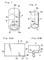
- FIG. 1 there is shown an outer metal jacket 6 as an embodiment of the invention, usable for construction of a dry cell.
- the metal jacket 6 is made up by forming a rectangular metal sheet member 7 as shown in Fig. 2 (A) into a cylindrical shape, butting both side edges 7a and 7b and welding the butted part 8 by CO2 laser to make a cylindrical body, of which the lower rim is then folded inwardly to make an annular bottom 6a.
- the rectangular metal sheet member 7 as shown in Fig. 2 is obtained by cutting or press cutting a metal sheet member. Then, its corner portions at the crossings of the side edge 7a with the upper edge 7c and with the lower edge 7d are cut off by a cutter to form notch portions 9a and 9b. Further, a notch 10 is formed by a cutter at a pre-determined position of the lower edge 7d near the notch portion 9b, i.e. near the crossing of the lower edge 7d with the side edge 7a or 7b.
- the notch 10 may have any appropriate shape such as V-letter shape, U-letter shape or semi-round shape and preferably takes such a shape having a height (H) of about 1.5 mm, a width (W) of about 1.4 mm and an opening angle (from the inside to the outside) of about 20° as shown in Fig. 2 (B), in which the part between the notch portion 9b and the notch 10 encompassed by a dotted line has a smaller mechanical strength in comparison with any other part on the lower edge 74 and serves as a safety mechanism.
- the side edges 7a and 7b of the metal sheet member 7 are joined togerther by any conventional procedure.
- the most typical joining procedure is welding such as fusion welding or pressure welding.
- laser welding is favorable, because the butted portion does not substantially form any inward protuberance so that an electrochemical cell system to be incorporated therein can have a larger diameter and consequently have a larger capacity.
- Joining may be accomplished also by bonding with any bonding agent.
- the butted portion 8 joined by various procedures is shown with enlargement in Fig. 4, and Figs 4 (A), 4 (B) and 4(C) show respectively the butted portions joined by laser welding, pressure welding and bonding with a bonding agent.
- the butted portion 8 thus joined has great joint strength and high air-tightness in comparision with joining by a double-locking system or a butting system. Therefore, a dry cell with an outer metal jacket joined by welding or bonding does not produce leakage of the electrolyte and is of high quality.
- the safety mechanism may be constituted with the part between the notch portion 9b and the notch 10, which is integrally formed on the annular bottom 6a of the metal jacket 6 (cf. Fig. 1).
- the distance between the notch portion 9b and the notch 10 may be, for instance, about 1 cm when the metal jacket 6 is used for a dry cell of Unit I (i.e. LR 20 under IEC or L 90 under ANSI). Since the notch portion 9b and the notch 10 are provided on the identical rim in a relatively close distance as understood above, the part between them has small mechanical strength in comparision with any other part.
- between the notch portion 9 and the notch 10 may be usually within about 90°, preferably from about 15 to 50°, so as to make the part between them smaller in mechanical strength than any other part and facilitate its opening to the outside on the rise of the inner pressure of the dry cell.
- Fig. 5 which is a fragmentary view partially taken away to show the inner structure of the lower part of a dry cell 12 accommodated in an outer metal jacket 6 provided with a safety mechanism 11, 13 is a Leclanche type cell element comprising the manganese dioxide/zinc system as sealed, 14 is an anode terminal plate and 15 is a seal packing interposed between the metal jacket 6 and the terminal plate 14.
- the metal jacket 6 functions in a normal or ordinary manner as shown in Fig. 5.
- the dry cell 12 has the same clamping strength in the vertical direction as a conventional one, and any difference in storage performances and leakage resistance is not present between them.
- gas may be generated from the electrochemical cell system in the metal jacket 6, and the inner pressure in the dry cell rises.
- the mechanically weak part as the safety mechanism 11 on the annular bottom 6a is opened outwardly due to the generated gas, whereby the anode terminal plate 14 is partly separated from the annular bottom 6a at the position corresponding to the safety mechanism 11 to release the generated gas therethrough to the outside.
- the rise of the inner pressure in the dry cell 12 is prevented, and disengagement of the seal plate integrally forming a cathode cap and spread of the depolarizer mix to the outside can be inhibited.
- the part between the notch portion 9 and the notch 10 having an opening angle of 90° or less is used as a safety mechanism 11.
- a score of small thickness may be used.
- FIGs. 7 and 8 there is shown an embodiment of an outer metal jacket 17 provided with a score 16.
- a groove 19 is formed on the inside at the lower rim of a metal sheet member 18 to give a score.
- the part between the score 16 and the notch portion 17a is smaller in mechanical strength than any other part and is thus available as a safety mechanism 20.
- the cutout portion is not exposed to the outside so that the air-tightness of the dry cell on the proper use is kept well and the appearance can be kept better.
- the score 21 and the notch 22 may be formed continuously to make a safety mechanism 23.
- the rise of the inner pressure in the dry cell produces stress concentration onto the notch so that the outward folding of the safety mechanism 23 (resulting in cutting of the score portion 16) takes place more assuredly than that of the safety mechanism 20 constituted with the score 16 alone as shown in Fig. 7, and the safety of the dry cell can be enhanced.
- the safety mechanisms 11, 20 and 23 are respectively formed near the notch portions 9b, 17a and 25a on the lower rims of the metal plates 7, 18 and 24.
- this invention is not necessarily limited thereto, and a safety mechanism may be provided on the upper rims of the metal plates 7, 18 and 24. If desired, the safety mechanisms may be provided not on either one of the lower and upper rims but on both of them.
- the combination is not necessarily limited to the one between the notch portion 9b, 17a or 25a and the notch 10 or 22 or the score 16 or 21, and as shown in Fig. 11, a plural number of notches or scores such as the notchs 27a and 27b may be formed with an opening angle ( ⁇ ) of 90° or less at different positions from the notch portion 26a corresponding to the butted part to make a safety mechanism 28.
- the invention has been explained hereinabove with respect to the metal jacket formed by seaming the metal sheet member 7, 18 or 24 at both side edges, for instance, by laser welding.
- this invention is not limited thereto and may be applied to any outer metal jacket as prepared by any other method.
- notches or scores as the safety mechanism may be provided on a seamless metal jacket formed by drawing.
- a dry cell prepared by the use of an outer metal jacket according to the invention can maintain high air-tightness on its proper use and surely prevent leakage of the electrolyte.
- gas On its improper use, for instance, gas may be generated causing expansion, but in such case, the safety mechanism having small mechanical strength is folded outwardly and the gas is released to the outside therethrough. Accordingly, the reliability and safety of a dry cell can be increased on the proper use and the improper use.
Landscapes
- Chemical & Material Sciences (AREA)
- Chemical Kinetics & Catalysis (AREA)
- Electrochemistry (AREA)
- General Chemical & Material Sciences (AREA)
- Sealing Battery Cases Or Jackets (AREA)
- Rigid Containers With Two Or More Constituent Elements (AREA)
- Battery Mounting, Suspending (AREA)
Abstract
Description
- The present invention relates to a metal jacket and a dry cell using the same. More particularly, it relates to an outer metal jacket (or cladding) provided with a safety mechanism and a dry cell of high safety using the same for prevention from breakage or rupture.
- In recent years, cylindrical dry cells were changed from a paper jacket type to a metal jacket type, and their resistance to leakage and expansion was much improved and their cells performances were significantly enhanced.
- An outer metal jacket for such dry cell is formed by joining a rectangular
metal sheet member 1, as shown in Fig. 12 of the accompanying drawings, at bothside edges lower rim 1c inwardly. The plane view and the bottom view of the thus formedmetal jacket 2 are shown in Figs. 13 (A) and 13 (B), respectively. Into theouter metal jacket 2, various components for constituting an electrochemical cell system are incorporated, and ultimately theupper rim 1d is folded inwardly to make a dry cell, of which the inside is made air-tight. - For joining both
side edges said plate 1, there are usually adopted a double-locking system wherein said edges are folded in a double layered or overlapped state, a butting system wherein said edges are butted each other, etc. In addition, there is recently developed a laser-welding system which assures firm joining. - For comparison, a
metal jacket 3 of the double-locking system and ametal jacket 4 of the laser-welding system are respectively shown in Figs. 14 (A) and 14 (B), and ametal jacket 4 of the laser-welding system and ametal jacket 5 of the butting system are respectively shown in Figs. 15 (A) and 15 (B). As understood from such comparison, the laser-welding system jacket 4 does not have any inward protrusion like the double-locking part 3a in the double-locking system jacket 3 and therefore can accommodate an electrochemical cell system with a zinc can having a larger outer diameter corresponding to the size (α) of the double-locking part 3a. Thus, the laser-welding system jacket 4 makes it possible to provide a dry cell having a larger capacity. Also, the laser-welding system jacket 4 has a higher tensile strength in the radial direction than thebutting system jacket 5, and therefore the former does not produce an opening at the butting part as seen in the latter even on excessive discharge. - When, however, a dry cell comprising a laser-welding system jacket firmly jointed at the butting part is used improperly, for example, under charge or left at a high temperature such as 85°C or more, the electrochemical cell system produces a gas so that the inner pressure increases causing the expansion of the dry cell. Since the tensile strength of the laser-welding system jacket in the radial direction is great, the expansion caused by the increase of the inner pressure takes place in the vertical direction thus producing such troubles as the disengagement of the seal plate as the cathode cap provided at the upper part of the dry cell and the spread of the depolarizer mix to the outside. As the result, the appliance incorporated with the dry cell will be heavily damaged, and serious accidents may happen in some cases.
- Accordingly, it is a basic object of the present invention to provide an outer metal jacket provided with a safety mechanism so as to prevent a dry cell constructed therewith from its breakage or rupture due to the abnormal rise of its inner pressure. Another object of this invention is to provide a dry cell of high safety using said metal jacket. These and other objects of the invention will be apparent from the foregoing and subsequent descriptions.
- According to this invention, there is provided an outer metal jacket formed by joining a rectangular metal sheet member at both side edges, characterized in that it is integrally provided with a mechanically weaker part as a safety mechanism at the upper or lower rim in comparison with any other part of the metal jacket.
- The metal jacket may be formed by butting a rectangular metal sheet member at both side edges and seaming the butted part by welding such as laser welding or fusion welding or bonding with a bonding agent.
- The mechanically weaker part (i.e. the part having a smaller mechanical strength) as the safety mechanism may be provided on the upper and/or lower rim(s) of the metal jacket in various ways. An example of the ways is to provide a notch portion, e.g. in a wedge shape, on at least one of the upper and lower rims at the position corresponding to the butted part corresponding to the butted part and a cutout notch on the same rim where said notch portion is provided so as to make the part between the notch portion and the cutout notch weaker in mechanical strength in comparison with any other part. Instead of said notch portion, a cutout notch may be provided at any other part on the rim; namely, in this case, two or more cutout notches are provided on at least one of the upper and lower rims.
- Another example is to provide a notch portion on at least one of the upper and lower rims at the position corresponding to the butted part corresponding to the butted part and a score of small thickness on the same rim where said notch portion is provided so as to make the part between the notch portion and the score weaker in mechanical strength in comparision with any other part. Instead of said notch portion, a score may be provided at any other part on the rim; namely, in this case, two or more scores are provided on at least one of the upper and lower rims.
- In the above examples, a notch or score may be provided continuously with a score or notch; namely, a notch and a score may be provided in combination.
- For construction of a dry cell, an electrochemical cell system as sealed is incorporated into the metal jacket, followed by clamping the upper and lower rims of the metal jacket inwardly. In a preferred embodiment, the opening angle between the notch portion in a wedge shape and the notch adjacent thereto or between two notches adjacent to ech other may be kept within 90° so that the part between them as the safety mechanism will be opened outwardly on the abnormal increase of the inner pressure in the dry cell.
- Since the outer metal jacket of the invention is provided with the safety mechanism as above, the abnormal rise of the inner pressure in the dry cell manufactured by the use of such metal jacekt due to its improper use makes the safety mechanism opened resulting in reduction of the inner pressure, whereby brekage or rupture of the dry cell with disengagement of its seal plate as the cathode cap and spread of the depolarizer mix can be prevented.
- The present invention will become more apparent from the following description when considered with the accompanying drawings wherein:
- Fig. 1 is a vertical view of an outer metal jacket as an embodiment of the invention;
- Fig. 2 (A) is a plane view of a metal sheet member for formation of an outer metal jacket as an embodiment of the invention, and Fig. 2 (B) is an expanded plane view of the lower and right side part of said metal sheet member;
- Fig. 3 is a vertical view of a metal sheet member butted and jointed at both side edges for formation of an outer metal jacket as an embodiment of the invention;
- Figs. 4 (A), 4 (B) and 4 (C) show expanded section views of the butted part of a metal sheet member as butted in different ways;
- Fig. 5 is a fragmentary view partially taken away to show the lower inside of a dry cell using an outer metal jacket as an embodiment of the invention on the proper use (i.e. in a state that the safety mechanism is not operated);
- Fig. 6 is a fragmentary view partially taken away to show the lower inside of a dry cell using an outer metal jacket as an embodiment of the invention on the improper use (i.e. in a state where the safety mechanism is operated);
- Fig. 7 is an explanatory bottom view of an outer metal jacket as an embodiment of the invention, of which the safety mechanism comprises a score;
- Fig. 8 is an expanded section view cut at the A-A line in Fig. 7;
- Fig. 9 is an explanatory bottom view of an outer metal jacket as an embodiment of the invention, of which the safety mechanism comprises a score and a notch continuously provided;
- Fig. 10 is an expanded section view cut at the B-B line in Fig. 9;
- Fig. 11 is an explanatory bottom view of an outer metal jacket as an embodiment of the invention, of which the safety mechanism comprises a plural number of notches;
- Fig. 12 is a plane view of a metal sheet member for forming a conventional outer metal jacket;
- Figs. 13 (A) and 13 (B) are respectively explanatory plane and bottom views of a conventional outer metal jacket;
- Figs. 14 (A) and 14 (B) are respectively explanatory views of a double-locking jacket system and a laser-welding jacket system;
- Figs. 15 (A) and 15 (B) are respectively explanatory views of a laser-welding system jacket and a butting jacket system.
- In Fig. 1, there is shown an
outer metal jacket 6 as an embodiment of the invention, usable for construction of a dry cell. Themetal jacket 6 is made up by forming a rectangularmetal sheet member 7 as shown in Fig. 2 (A) into a cylindrical shape, butting bothside edges part 8 by CO₂ laser to make a cylindrical body, of which the lower rim is then folded inwardly to make anannular bottom 6a. - The rectangular
metal sheet member 7 as shown in Fig. 2 is obtained by cutting or press cutting a metal sheet member. Then, its corner portions at the crossings of theside edge 7a with theupper edge 7c and with thelower edge 7d are cut off by a cutter to formnotch portions notch 10 is formed by a cutter at a pre-determined position of thelower edge 7d near thenotch portion 9b, i.e. near the crossing of thelower edge 7d with theside edge notch 10 may have any appropriate shape such as V-letter shape, U-letter shape or semi-round shape and preferably takes such a shape having a height (H) of about 1.5 mm, a width (W) of about 1.4 mm and an opening angle (from the inside to the outside) of about 20° as shown in Fig. 2 (B), in which the part between thenotch portion 9b and thenotch 10 encompassed by a dotted line has a smaller mechanical strength in comparison with any other part on the lower edge 74 and serves as a safety mechanism. - For manufacture of the
metal jacket 6, theside edges metal sheet member 7 are joined togerther by any conventional procedure. The most typical joining procedure is welding such as fusion welding or pressure welding. Among various fusion welding processes, laser welding is favorable, because the butted portion does not substantially form any inward protuberance so that an electrochemical cell system to be incorporated therein can have a larger diameter and consequently have a larger capacity. Joining may be accomplished also by bonding with any bonding agent. - The butted
portion 8 joined by various procedures is shown with enlargement in Fig. 4, and Figs 4 (A), 4 (B) and 4(C) show respectively the butted portions joined by laser welding, pressure welding and bonding with a bonding agent. The buttedportion 8 thus joined has great joint strength and high air-tightness in comparision with joining by a double-locking system or a butting system. Therefore, a dry cell with an outer metal jacket joined by welding or bonding does not produce leakage of the electrolyte and is of high quality. - Explaining the safety mechanism according to this invention, it may be constituted with the part between the
notch portion 9b and thenotch 10, which is integrally formed on theannular bottom 6a of the metal jacket 6 (cf. Fig. 1). The distance between thenotch portion 9b and thenotch 10 may be, for instance, about 1 cm when themetal jacket 6 is used for a dry cell of Unit I (i.e.LR 20 under IEC or L 90 under ANSI). Since thenotch portion 9b and thenotch 10 are provided on the identical rim in a relatively close distance as understood above, the part between them has small mechanical strength in comparision with any other part. The opening angle (cf. (β) in Fig. 1) between the notch portion 9 and thenotch 10 may be usually within about 90°, preferably from about 15 to 50°, so as to make the part between them smaller in mechanical strength than any other part and facilitate its opening to the outside on the rise of the inner pressure of the dry cell. - In Fig. 5, which is a fragmentary view partially taken away to show the inner structure of the lower part of a
dry cell 12 accommodated in anouter metal jacket 6 provided with asafety mechanism metal jacket 6 and theterminal plate 14. - On the proper use of the
dry cell 12, themetal jacket 6 functions in a normal or ordinary manner as shown in Fig. 5. Thus, thedry cell 12 has the same clamping strength in the vertical direction as a conventional one, and any difference in storage performances and leakage resistance is not present between them. - When, however, the
dry cell 12 is on the improper use, gas may be generated from the electrochemical cell system in themetal jacket 6, and the inner pressure in the dry cell rises. As shown in Fig. 6, the mechanically weak part as thesafety mechanism 11 on theannular bottom 6a is opened outwardly due to the generated gas, whereby theanode terminal plate 14 is partly separated from theannular bottom 6a at the position corresponding to thesafety mechanism 11 to release the generated gas therethrough to the outside. As the result, the rise of the inner pressure in thedry cell 12 is prevented, and disengagement of the seal plate integrally forming a cathode cap and spread of the depolarizer mix to the outside can be inhibited. - In the above embodiments, the part between the notch portion 9 and the
notch 10 having an opening angle of 90° or less is used as asafety mechanism 11. In place of saidnotch 10, a score of small thickness may be used. In Figs. 7 and 8, there is shown an embodiment of anouter metal jacket 17 provided with ascore 16. As shown in Fig. 8, agroove 19 is formed on the inside at the lower rim of ametal sheet member 18 to give a score. the part between thescore 16 and thenotch portion 17a is smaller in mechanical strength than any other part and is thus available as asafety mechanism 20. In themetal jacket 17 provided with a safety mechanism of this kind, the cutout portion is not exposed to the outside so that the air-tightness of the dry cell on the proper use is kept well and the appearance can be kept better. - As shown in Figs. 9 and 10, the
score 21 and thenotch 22 may be formed continuously to make asafety mechanism 23. When the safety mechanism is thus con structed, the rise of the inner pressure in the dry cell produces stress concentration onto the notch so that the outward folding of the safety mechanism 23 (resulting in cutting of the score portion 16) takes place more assuredly than that of thesafety mechanism 20 constituted with thescore 16 alone as shown in Fig. 7, and the safety of the dry cell can be enhanced. - In the above embodiments, the
safety mechanisms notch portions metal plates metal plates notch portion notch score notchs 27a and 27b may be formed with an opening angle (β) of 90° or less at different positions from thenotch portion 26a corresponding to the butted part to make asafety mechanism 28. - The invention has been explained hereinabove with respect to the metal jacket formed by seaming the
metal sheet member - As understood from the above, a dry cell prepared by the use of an outer metal jacket according to the invention can maintain high air-tightness on its proper use and surely prevent leakage of the electrolyte. On its improper use, for instance, gas may be generated causing expansion, but in such case, the safety mechanism having small mechanical strength is folded outwardly and the gas is released to the outside therethrough. Accordingly, the reliability and safety of a dry cell can be increased on the proper use and the improper use.
Claims (12)
Applications Claiming Priority (2)
| Application Number | Priority Date | Filing Date | Title |
|---|---|---|---|
| JP56652/88 | 1988-03-10 | ||
| JP63056652A JPH0682546B2 (en) | 1988-03-10 | 1988-03-10 | Outer can and dry battery using the same |
Publications (2)
| Publication Number | Publication Date |
|---|---|
| EP0333023A1 true EP0333023A1 (en) | 1989-09-20 |
| EP0333023B1 EP0333023B1 (en) | 1994-09-07 |
Family
ID=13033299
Family Applications (1)
| Application Number | Title | Priority Date | Filing Date |
|---|---|---|---|
| EP89104156A Expired - Lifetime EP0333023B1 (en) | 1988-03-10 | 1989-03-09 | Metal jacket and dry cell using the same |
Country Status (5)
| Country | Link |
|---|---|
| US (1) | US4965149A (en) |
| EP (1) | EP0333023B1 (en) |
| JP (1) | JPH0682546B2 (en) |
| KR (1) | KR920004294B1 (en) |
| DE (1) | DE68917959T2 (en) |
Cited By (2)
| Publication number | Priority date | Publication date | Assignee | Title |
|---|---|---|---|---|
| EP1011156A1 (en) * | 1998-11-10 | 2000-06-21 | Japan Storage Battery Company Limited | Battery cell with a safety valve |
| US6228530B1 (en) * | 1997-09-03 | 2001-05-08 | Matsushita Electric Industrial Co., Ltd. | Dry cell and method of manufacturing outer metal jacket thereof |
Families Citing this family (6)
| Publication number | Priority date | Publication date | Assignee | Title |
|---|---|---|---|---|
| FI980962L (en) * | 1998-04-30 | 1999-10-31 | Nokia Mobile Phones Ltd | Arrangement for implementing protection in the battery and the battery |
| US6159631A (en) * | 1998-08-27 | 2000-12-12 | Polystor Corporation | Overcharge safety vents on prismatic cells |
| USD535945S1 (en) * | 2004-04-15 | 2007-01-30 | Towler Peter J | Nested kit for replacing a larger battery with a smaller battery |
| KR101023919B1 (en) | 2008-06-09 | 2011-03-22 | 삼성에스디아이 주식회사 | Lithium secondary battery |
| KR101182274B1 (en) * | 2010-10-13 | 2012-09-13 | 삼성에스디아이 주식회사 | Rechargeable battery and manufacturing method of the same |
| KR101711984B1 (en) | 2013-07-16 | 2017-03-03 | 삼성에스디아이 주식회사 | Rechargeable battery |
Citations (5)
| Publication number | Priority date | Publication date | Assignee | Title |
|---|---|---|---|---|
| FR1097049A (en) * | 1953-03-03 | 1955-06-28 | Sealed enclosure for electric batteries and other galvanic elements | |
| DE975894C (en) * | 1951-07-18 | 1962-12-20 | Hans Dr H C Vogt | Housing of accumulator cells acting as overpressure protection |
| DE2146365A1 (en) * | 1971-09-16 | 1973-03-22 | Hellesens As | PROTECTIVE COAT FOR CYLINDRICAL DRY ELEMENTS |
| US4079172A (en) * | 1977-03-30 | 1978-03-14 | Union Carbide Corporation | Galvanic cell having a high pressure vent closure |
| US4227701A (en) * | 1979-01-02 | 1980-10-14 | Fuji Electrochemical Co., Ltd. | Rupturable sealing structure of cell |
Family Cites Families (9)
| Publication number | Priority date | Publication date | Assignee | Title |
|---|---|---|---|---|
| GB1197304A (en) * | 1966-08-16 | 1970-07-01 | Matsushita Electric Industrial Co Ltd | Battery |
| US4484691A (en) * | 1975-11-03 | 1984-11-27 | Duracell Inc. | Pressure release device |
| JPS53133469A (en) * | 1977-04-27 | 1978-11-21 | Seiko Epson Corp | Charging type wristwatch |
| JPS575261A (en) * | 1980-06-12 | 1982-01-12 | Casio Comput Co Ltd | Alkaline battery |
| JPS6119053A (en) * | 1984-07-06 | 1986-01-27 | Fuji Elelctrochem Co Ltd | Cylindrical battery |
| US4610370A (en) * | 1985-12-30 | 1986-09-09 | Amoco Corporation | Pressure release vent |
| US4698282A (en) * | 1986-06-02 | 1987-10-06 | Power Conversion Inc. | Safety vent device for electrochemical cells |
| US4722874A (en) * | 1986-08-01 | 1988-02-02 | Moli Energy Limited | Electrochemical cell pressure relief devices |
| US4789608A (en) * | 1987-03-26 | 1988-12-06 | Saft America, Inc. | Pressure venting device |
-
1988
- 1988-03-10 JP JP63056652A patent/JPH0682546B2/en not_active Expired - Fee Related
-
1989
- 1989-03-09 EP EP89104156A patent/EP0333023B1/en not_active Expired - Lifetime
- 1989-03-09 DE DE68917959T patent/DE68917959T2/en not_active Expired - Fee Related
- 1989-03-09 KR KR1019890002888A patent/KR920004294B1/en not_active Expired
- 1989-03-10 US US07/321,746 patent/US4965149A/en not_active Expired - Lifetime
Patent Citations (5)
| Publication number | Priority date | Publication date | Assignee | Title |
|---|---|---|---|---|
| DE975894C (en) * | 1951-07-18 | 1962-12-20 | Hans Dr H C Vogt | Housing of accumulator cells acting as overpressure protection |
| FR1097049A (en) * | 1953-03-03 | 1955-06-28 | Sealed enclosure for electric batteries and other galvanic elements | |
| DE2146365A1 (en) * | 1971-09-16 | 1973-03-22 | Hellesens As | PROTECTIVE COAT FOR CYLINDRICAL DRY ELEMENTS |
| US4079172A (en) * | 1977-03-30 | 1978-03-14 | Union Carbide Corporation | Galvanic cell having a high pressure vent closure |
| US4227701A (en) * | 1979-01-02 | 1980-10-14 | Fuji Electrochemical Co., Ltd. | Rupturable sealing structure of cell |
Non-Patent Citations (3)
| Title |
|---|
| PATENT ABSTRACTS OF JAPAN, vol. 10, no. 168 (E-411)[2224], 14th June 1986; & JP-A-61 019 053 (FUJI DENKI KAGAKU K.K.) 27-01-1986 * |
| PATENT ABSTRACTS OF JAPAN, vol. 3, no. 6 (E-85), 22nd January 1979, page 56 E85; & JP-A-53 133 469 (SUWA SEIKOSHA K.K.) 21-11-1978 * |
| PATENT ABSTRACTS OF JAPAN, vol. 6, no. 64 (E-103)[942], 23rd April 1982; & JP-A-57 005 261 (CASIO KEISANKI K.K.) 12-01-1982 * |
Cited By (4)
| Publication number | Priority date | Publication date | Assignee | Title |
|---|---|---|---|---|
| US6228530B1 (en) * | 1997-09-03 | 2001-05-08 | Matsushita Electric Industrial Co., Ltd. | Dry cell and method of manufacturing outer metal jacket thereof |
| EP0951079A4 (en) * | 1997-09-03 | 2004-09-29 | Matsushita Electric Industrial Co Ltd | DRY CELL AND METHOD FOR MANUFACTURING AN EXTERNAL HOUSING FOR THE SAME |
| EP1011156A1 (en) * | 1998-11-10 | 2000-06-21 | Japan Storage Battery Company Limited | Battery cell with a safety valve |
| US6432572B1 (en) | 1998-11-10 | 2002-08-13 | Japan Storage Battery Co., Ltd. | Battery valve and battery using the same |
Also Published As
| Publication number | Publication date |
|---|---|
| KR890015442A (en) | 1989-10-30 |
| KR920004294B1 (en) | 1992-06-01 |
| DE68917959T2 (en) | 1995-05-04 |
| JPH0682546B2 (en) | 1994-10-19 |
| US4965149A (en) | 1990-10-23 |
| EP0333023B1 (en) | 1994-09-07 |
| JPH01231262A (en) | 1989-09-14 |
| DE68917959D1 (en) | 1994-10-13 |
Similar Documents
| Publication | Publication Date | Title |
|---|---|---|
| CN102057516B (en) | Closed components with low vapor permeation for electrochemical cells | |
| US6159631A (en) | Overcharge safety vents on prismatic cells | |
| US7601460B2 (en) | Prismatic battery and manufacturing method thereof | |
| EP1150371B1 (en) | Electrode plate unit and battery | |
| US6951576B1 (en) | Wound element electrode assembly design for use in prismatic case electrochemical cells | |
| JP7622226B2 (en) | Cylindrical secondary battery, battery pack including same, and automobile | |
| CA2099657C (en) | Electrochemical cell and method of manufacturing same | |
| JP2009146645A (en) | Welded structure manufacturing method and battery manufacturing method | |
| US6620543B2 (en) | Electrochemical cell having can vent and cover terminal | |
| JP2005203262A (en) | Film exterior electrical device | |
| KR20110129911A (en) | Closed assembly for electrochemical cell | |
| US20090296316A1 (en) | Capacitor | |
| KR20110131218A (en) | Closed assembly for electrochemical cell | |
| EP0333023A1 (en) | Metal jacket and dry cell using the same | |
| JP7160340B2 (en) | secondary battery | |
| JP2005183360A (en) | Square battery and manufacturing method thereof | |
| EP1261991B1 (en) | Manganese dry battery | |
| WO2000072389A1 (en) | Separator for electrochemical cell and method of assembly | |
| JPH10125335A (en) | Battery with spiral electrode and method of manufacturing the same | |
| JPH04349347A (en) | Sealed battery | |
| KR102824719B1 (en) | Cylindrical secondary battery cell, and battery pack and vehicle including the same | |
| JP7120026B2 (en) | secondary battery | |
| US4927719A (en) | Dry cell | |
| KR20240070397A (en) | Secondary battery and manufacturing method for the same | |
| KR102918560B1 (en) | Button type secondary battery |
Legal Events
| Date | Code | Title | Description |
|---|---|---|---|
| PUAI | Public reference made under article 153(3) epc to a published international application that has entered the european phase |
Free format text: ORIGINAL CODE: 0009012 |
|
| 17P | Request for examination filed |
Effective date: 19890317 |
|
| AK | Designated contracting states |
Kind code of ref document: A1 Designated state(s): BE DE FR IT |
|
| 17Q | First examination report despatched |
Effective date: 19910809 |
|
| GRAA | (expected) grant |
Free format text: ORIGINAL CODE: 0009210 |
|
| AK | Designated contracting states |
Kind code of ref document: B1 Designated state(s): BE DE FR IT |
|
| ITF | It: translation for a ep patent filed | ||
| REF | Corresponds to: |
Ref document number: 68917959 Country of ref document: DE Date of ref document: 19941013 |
|
| ET | Fr: translation filed | ||
| PLBE | No opposition filed within time limit |
Free format text: ORIGINAL CODE: 0009261 |
|
| STAA | Information on the status of an ep patent application or granted ep patent |
Free format text: STATUS: NO OPPOSITION FILED WITHIN TIME LIMIT |
|
| 26N | No opposition filed | ||
| PGFP | Annual fee paid to national office [announced via postgrant information from national office to epo] |
Ref country code: FR Payment date: 20030310 Year of fee payment: 15 |
|
| PGFP | Annual fee paid to national office [announced via postgrant information from national office to epo] |
Ref country code: DE Payment date: 20030320 Year of fee payment: 15 |
|
| PGFP | Annual fee paid to national office [announced via postgrant information from national office to epo] |
Ref country code: BE Payment date: 20030514 Year of fee payment: 15 |
|
| PG25 | Lapsed in a contracting state [announced via postgrant information from national office to epo] |
Ref country code: BE Free format text: LAPSE BECAUSE OF NON-PAYMENT OF DUE FEES Effective date: 20040331 |
|
| BERE | Be: lapsed |
Owner name: *MATSUSHITA ELECTRIC INDUSTRIAL CO. LTD Effective date: 20040331 |
|
| PG25 | Lapsed in a contracting state [announced via postgrant information from national office to epo] |
Ref country code: DE Free format text: LAPSE BECAUSE OF NON-PAYMENT OF DUE FEES Effective date: 20041001 |
|
| PG25 | Lapsed in a contracting state [announced via postgrant information from national office to epo] |
Ref country code: FR Free format text: LAPSE BECAUSE OF NON-PAYMENT OF DUE FEES Effective date: 20041130 |
|
| REG | Reference to a national code |
Ref country code: FR Ref legal event code: ST |
|
| PG25 | Lapsed in a contracting state [announced via postgrant information from national office to epo] |
Ref country code: IT Free format text: LAPSE BECAUSE OF NON-PAYMENT OF DUE FEES;WARNING: LAPSES OF ITALIAN PATENTS WITH EFFECTIVE DATE BEFORE 2007 MAY HAVE OCCURRED AT ANY TIME BEFORE 2007. THE CORRECT EFFECTIVE DATE MAY BE DIFFERENT FROM THE ONE RECORDED. Effective date: 20050309 |