EP0332308A2 - Waveform generator for electrosurgical apparatus - Google Patents
Waveform generator for electrosurgical apparatus Download PDFInfo
- Publication number
- EP0332308A2 EP0332308A2 EP89301516A EP89301516A EP0332308A2 EP 0332308 A2 EP0332308 A2 EP 0332308A2 EP 89301516 A EP89301516 A EP 89301516A EP 89301516 A EP89301516 A EP 89301516A EP 0332308 A2 EP0332308 A2 EP 0332308A2
- Authority
- EP
- European Patent Office
- Prior art keywords
- waveform
- bits
- output
- storage means
- waveform generator
- Prior art date
- Legal status (The legal status is an assumption and is not a legal conclusion. Google has not performed a legal analysis and makes no representation as to the accuracy of the status listed.)
- Withdrawn
Links
Images


Classifications
-
- A—HUMAN NECESSITIES
- A61—MEDICAL OR VETERINARY SCIENCE; HYGIENE
- A61B—DIAGNOSIS; SURGERY; IDENTIFICATION
- A61B18/00—Surgical instruments, devices or methods for transferring non-mechanical forms of energy to or from the body
- A61B18/04—Surgical instruments, devices or methods for transferring non-mechanical forms of energy to or from the body by heating
- A61B18/12—Surgical instruments, devices or methods for transferring non-mechanical forms of energy to or from the body by heating by passing a current through the tissue to be heated, e.g. high-frequency current
- A61B18/1206—Generators therefor
-
- A—HUMAN NECESSITIES
- A61—MEDICAL OR VETERINARY SCIENCE; HYGIENE
- A61B—DIAGNOSIS; SURGERY; IDENTIFICATION
- A61B18/00—Surgical instruments, devices or methods for transferring non-mechanical forms of energy to or from the body
- A61B18/04—Surgical instruments, devices or methods for transferring non-mechanical forms of energy to or from the body by heating
- A61B18/12—Surgical instruments, devices or methods for transferring non-mechanical forms of energy to or from the body by heating by passing a current through the tissue to be heated, e.g. high-frequency current
-
- A—HUMAN NECESSITIES
- A61—MEDICAL OR VETERINARY SCIENCE; HYGIENE
- A61B—DIAGNOSIS; SURGERY; IDENTIFICATION
- A61B18/00—Surgical instruments, devices or methods for transferring non-mechanical forms of energy to or from the body
- A61B2018/00636—Sensing and controlling the application of energy
- A61B2018/0066—Sensing and controlling the application of energy without feedback, i.e. open loop control
-
- A—HUMAN NECESSITIES
- A61—MEDICAL OR VETERINARY SCIENCE; HYGIENE
- A61B—DIAGNOSIS; SURGERY; IDENTIFICATION
- A61B18/00—Surgical instruments, devices or methods for transferring non-mechanical forms of energy to or from the body
- A61B2018/00636—Sensing and controlling the application of energy
- A61B2018/00684—Sensing and controlling the application of energy using lookup tables
Definitions
- This invention relates generally to improvements in electrosurgical apparatus and more particularly to a novel and improved waveform generator for controlling the power output of electrosurgical apparatus.
- Electrosurgical apparatus for cutting and the coagulation of tissue requires supplying a wide range of power outputs to the active electrode for a wide range of surgical procedures.
- Klicek U. S. Patent No. 4,658,820 discloses a waveform generator that stores several waveforms in an MxN storage device, each of these several waveforms being available simultaneously at the output of the storage device and with the desired waveform selected by a multiplexer. That disclosure requires that the read access time of the storage device be less than the highest bit rate of the resulting waveform, that each waveform length must be of a common multiple of every other waveform length, and that the number of waveforms that can be stored is limited by the length of the multiplexer used to select the output waveform. Those requirements place severe restrictions on the upper waveform frequency, diversity of waveform length, and the number of waveforms that may be used.
- the waveform generator disclosed includes a MxNxP waveform storage device, a parallel to serial conversion means loaded by the storage device for changing this stored waveform to a sequential or series output signal, and a means of controlling these operations.
- the sequential or series output signal drives the RF power amplifier connected to the active electrode of the electrosurgical apparatus.
- Control means preferably an address counter that selects each N bits of the waveform from the storage device has a selectable modulus without external decoding circuitry.
- a waveform generator 12 having eight select address input lines WV0 ⁇ -WV7 and RFEN input lines receiving outputs from a controller MP, preferably a programmed microprocessor.
- An additional input line WDTFL receives it's signal from a watchdog timer circuit (not shown).
- the RFEN line carries an RF enable signal supplied by the controller MP that will turn off the gates of the buffer U7A and U7B as required.
- the WDTFL line carries a watchdog timer fail signal supplied by a watchdog timer that will turn off the buffers if the microprocessor is not working properly.
- the waveform generator 12 shown has two outputs GATE A and GATE B which are applied to the input of a RF power amplifier 13 of the electrosurgical apparatus.
- An output circuit 15 couples the output of the RF power amplifier to a patient circuit 16 which includes an active electrode 18 and the return electrode 19.
- a VBASE signal from a digital to analog converter (not shown) is also applied as an input to the RF power amplifier to control the amplitude of the waveform generated by generator 12.
- a MxNxP storage device U1 is provided.
- the storage device shown is an EPROM.
- M is the maximum number of different waveforms that can be stored.
- P is the maximum number of N bits stored for each waveform.
- N is the number of bits being output from the storage device at a time.
- NxP is the maximum length of each waveform in number of bits outputted.
- the read access time of the storage device is less than N times the output bit stream.
- the waveform is selected through microprocessor control of the eight address lines WV0 ⁇ -WV7.
- An address counter made up of U2 and U3 provides a COUNTER LOAD signal to set the modulus of the counter, and SUBADDRESS lines A0 ⁇ -A6 to select the next N bits of the waveform.
- An N bit signal will be output from storage device U1 and loaded into a parallel-to-serial conversion device U6 preferably a parallel-in, series-out shift register.
- the shift register U6 converts the N bits to a sequential or serial output that is buffered by buffers U7A and U7B to provide the GATE A and GATE B outputs.
- the GATE A and GATE B outputs are two identical outputs both of which are used to drive one half of the RF POWER AMPLIFIER. This split drive allows the power amplifier to be partially functional even if one half of the power amplifier fails.
- a clock oscillator U4 generates a REFERENCE FREQUENCY signal which in a preferred embodiment is 20MHz.
- Each serial output bit preferably has a duration of 50 nanoseconds.
- the buffers U7A and U7B provide both buffer and enable functions.
- the most significant bit MSB which is QD of U2 is set high by the preload. This sets the load inputs/LD of U2 and U3 to their inactive state and allows the address counter to count. This counter keeps counting until full value 1111 1111 and then rolls over to 0 ⁇ 0 ⁇ 0 ⁇ 0 ⁇ 0 ⁇ 0 ⁇ 0 ⁇ 0 ⁇ , setting QD of U2 low and thus COUNTER LOAD low. On the next clock from SHIFT REGISTER LOAD there is loaded all of the inputs 00 ⁇ through 06 into the address counter U2, U3. This is to be distinguished from starting the counter at 0 ⁇ 0 ⁇ 0 ⁇ 0 ⁇ and decoding an output to reset. This feature gives a parts count advantage by eliminating a separate decoding device and also allows the use of a faster clock for the counter by eliminating the delay time associated with a separate decoding device.
- the SHIFT REGISTER LOAD signal goes low and then high to advance the count of the address counter U2, U3.
- the outputs from the address counter A0 ⁇ -A7 select the next N bit word to the loaded into shift register U6 from storage device U1.
- the COUNTER LOAD signal goes low on the next count and the address counter U2, U3 is preloaded to the pattern presented to it by 00 ⁇ -07 of storage device U1. This pattern sets the modulus of the address counter and the COUNTER LOAD signal also clears the shift register U6 to zero's to prevent putting the modulus pattern out to the RF power amplifier.
- the waveform generator 12 discussed herein stores the waveform to be output and can store several waveforms of unrelated frequency and bit patterns limited only by the clock oscillator U4 and the size of the storage device U1.
- the shift register U6 is loaded with data from the storage device U1 to allow a more complex bit pattern to be generated.
- the pulse is characterized by its pulse width or duration, and pulse repetition frequency or repetition rate.
- the minimum pulse width for the preferred embodiment is 50 nanoseconds.
- a wide variety of waveforms are possible from the waveform generator of the present invention to carry out a wide variety of surgical procedures.
- the RF frequency is 1.05 Mhz.
- the number of pulses that occur is controlled by the power setting on the front panel.
- the first waveform has no pulse and each consecutive waveform has an additional pulse with a selected time interval between pulses over the previous waveform.
- the unit is calibrated such that each pulse corresponds to one watt delivered to the rated load impedance.
- the maximum power setting for the bipolar coag made is 50 watts, thus the maximum number of pulses per waveform cycle is 50, and the number of required waveforms for this is 51.
- a bipolar cut mode operates at 1.00 Mhz and is controlled by the VBASE voltage that is supplied to the RF power amplifier 13.
- the purpose of a cut mode is to cut tissue with as little hemostasis as possible. This is done by supplying as much power with as little voltage and muscle stimulation as possible.
- the RF frequency for the monopolar cut is 416.7 Khz. This waveform makes use of the variable modulus for the waveform cycle.
- the monopolar blend mode provides cutting action with hemostasis. This is done by increasing the crest factor. Crest factor is equal to peak voltage divided by r.m.s. voltage. To do this, a normal cut waveform is used, but only at a partial duty cycle. This then requires a higher voltage to be used to deliver the required power, thus causing the desired hemostasis.
- a standard coagulation mode is used when hemostasis without a cutting action is desired. This mode has a higher crest factor than the monopolar blend (about 6 vs. 3 for blend and 1.7 for cut).
- Power is controlled by waveform selection. There are two pulses per waveform cycle and the length of each pulse increases with power setting. The length and PRF (pulse repetition frequency) of these pulses determines output voltage and power. With this waveform, first one pulse increases, then the other on the ensuing waveform when power is increased. This provides for a fine control of waveform power.
- a monopolar spray mode is used when even more peak voltage is required than monopolar standard coag. This would be used for a very bloody operating field such as the sternum. This mode has a crest factor of about 9. In order to generate the higher voltage without increasing the power delivery, the number of pulses per waveform cycle is half that of monopolar standard coag mode. Like monopolar standard coag and bipolar coag, output power is determined by waveform selection.
- the storage device U1 could be a RAM that is loaded by a microprocessor.
- the microprocessor could calculate the desired waveform to be stored in the RAM.
- a ROM or PROM could also be used.
- the counter preloads for the address counter U2,U3 could be fixed, with the stored waveform modified to accommodate this change. This would eliminate the requirement to clear the shift register when loading the modulus preload.
- the address counter preload could come from an independent source, i.e. a latched microprocessor input, or another storage device that uses the same waveform address lines as the waveform storage device, but contains only modulus lengths. This would also eliminate the requirement to clear the shift register when loading the modulus preload.
- the shift register U6 could be any parallel to serial conversion device such as a multiplexer with a counter.
- the clock oscillator U4 could be a different frequency, and could be controlled to offer variations of output frequency without adding to the size of the memory.
- the length of the parallel to serial converter could be different. This same length would be required for the modulus of the counter U5.
- the address counter U2, U3 could be a different length to accommodate a different waveform modulus or to use less memory when used only for shorter modulus waveforms.
- the advantages of the waveform generator of the present invention include a longer, more complex bit pattern and a variable length count.
- the preferred embodiment uses approximately 200 different waveforms and could store 256 different, independent waveforms.
- the modulus of the waveform is stored in the storage device so that the modulus can be set for each waveform without external intervention.
- the waveform generator of the present invention allows the use of a slower MxNxP memory device.
- the address counter modulus is set by preloading the value P - K/N into the waveform address counter and resetting when the count rolls over. K is the total number of bits output for each waveform.
Abstract
A waveform generator for electrosurgical apparatus disclosed includes a MxNxP storage device and a parallel to series conversion device. For the storage device, M is the maximum number of different waveforms being stored, N equals the number of bits being output from the storage device at a time and P is the maximum number of N bits that can be stored for each waveform. An address counter selects the next N bits of the waveform and these N bits are loaded from the storage device into the conversion device and output in a sequential or series output signal to drive the RF power amplifier of electrosurgical apparatus. The output signal has a bit rate N times faster than the storage device is accessed.
Description
- This invention relates generally to improvements in electrosurgical apparatus and more particularly to a novel and improved waveform generator for controlling the power output of electrosurgical apparatus.
- Electrosurgical apparatus for cutting and the coagulation of tissue requires supplying a wide range of power outputs to the active electrode for a wide range of surgical procedures.
- Klicek U. S. Patent No. 4,658,820 discloses a waveform generator that stores several waveforms in an MxN storage device, each of these several waveforms being available simultaneously at the output of the storage device and with the desired waveform selected by a multiplexer. That disclosure requires that the read access time of the storage device be less than the highest bit rate of the resulting waveform, that each waveform length must be of a common multiple of every other waveform length, and that the number of waveforms that can be stored is limited by the length of the multiplexer used to select the output waveform. Those requirements place severe restrictions on the upper waveform frequency, diversity of waveform length, and the number of waveforms that may be used.
- The waveform generator disclosed includes a MxNxP waveform storage device, a parallel to serial conversion means loaded by the storage device for changing this stored waveform to a sequential or series output signal, and a means of controlling these operations. The sequential or series output signal drives the RF power amplifier connected to the active electrode of the electrosurgical apparatus. Control means, preferably an address counter that selects each N bits of the waveform from the storage device has a selectable modulus without external decoding circuitry.
- Figure 1 is a schematic diagram of the waveform generator embodying features of the present invention associated with other parts of the electrosurgical apparatus.
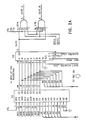
- Figure 2A and 2B is a more detailed circuit diagram of a waveform generator shown in block form in Figure 1.
- Referring now to Figure 1 there is shown a
waveform generator 12 having eight select address input lines WV0̸-WV7 and RFEN input lines receiving outputs from a controller MP, preferably a programmed microprocessor. An additional input line WDTFL receives it's signal from a watchdog timer circuit (not shown). The RFEN line carries an RF enable signal supplied by the controller MP that will turn off the gates of the buffer U7A and U7B as required. The WDTFL line carries a watchdog timer fail signal supplied by a watchdog timer that will turn off the buffers if the microprocessor is not working properly. Thewaveform generator 12 shown has two outputs GATE A and GATE B which are applied to the input of aRF power amplifier 13 of the electrosurgical apparatus. Anoutput circuit 15 couples the output of the RF power amplifier to apatient circuit 16 which includes anactive electrode 18 and thereturn electrode 19. A VBASE signal from a digital to analog converter (not shown) is also applied as an input to the RF power amplifier to control the amplitude of the waveform generated bygenerator 12. - Referring now to Figures 2A and 2B, a MxNxP storage device U1 is provided. The storage device shown is an EPROM. M is the maximum number of different waveforms that can be stored. P is the maximum number of N bits stored for each waveform. N is the number of bits being output from the storage device at a time. NxP is the maximum length of each waveform in number of bits outputted. The read access time of the storage device is less than N times the output bit stream. The waveform is selected through microprocessor control of the eight address lines WV0̸-WV7.
- An address counter made up of U2 and U3 provides a COUNTER LOAD signal to set the modulus of the counter, and SUBADDRESS lines A0̸-A6 to select the next N bits of the waveform. An N bit signal will be output from storage device U1 and loaded into a parallel-to-serial conversion device U6 preferably a parallel-in, series-out shift register. The shift register U6 converts the N bits to a sequential or serial output that is buffered by buffers U7A and U7B to provide the GATE A and GATE B outputs. The GATE A and GATE B outputs are two identical outputs both of which are used to drive one half of the RF POWER AMPLIFIER. This split drive allows the power amplifier to be partially functional even if one half of the power amplifier fails.
- A clock oscillator U4 generates a REFERENCE FREQUENCY signal which in a preferred embodiment is 20MHz. Each serial output bit preferably has a duration of 50 nanoseconds. The buffers U7A and U7B provide both buffer and enable functions.
- A counter U5 is configured as a divide by N (N=8 in this embodiment) and has a QD output set high when it is loaded with the preset values. As the count increases from it's preload value to a 1111 output and then rolls over to a 0̸0̸0̸0̸ output, QD goes low, loads shift register U6 with the outputs (00̸-07) of storage device U1, and synchronously loads counter U5 to it's preload state of 10̸0̸1. Shift register U6 then synchronously and sequentially shifts those outputs through its own output labeled GATE at the REFERENCE FREQUENCY rate. This is the unbuffered drive signal for the power amplifier.
- With reference to address counter U2,U3, the most significant bit MSB which is QD of U2 is set high by the preload. This sets the load inputs/LD of U2 and U3 to their inactive state and allows the address counter to count. This counter keeps counting until full value 1111 1111 and then rolls over to 0̸0̸0̸0̸ 0̸0̸0̸0̸, setting QD of U2 low and thus COUNTER LOAD low. On the next clock from SHIFT REGISTER LOAD there is loaded all of the inputs 00̸ through 06 into the address counter U2, U3. This is to be distinguished from starting the counter at 0̸0̸0̸0̸ and decoding an output to reset. This feature gives a parts count advantage by eliminating a separate decoding device and also allows the use of a faster clock for the counter by eliminating the delay time associated with a separate decoding device.
- Each time counter U5 cycles through it's count, the SHIFT REGISTER LOAD signal goes low and then high to advance the count of the address counter U2, U3. The outputs from the address counter A0̸-A7 select the next N bit word to the loaded into shift register U6 from storage device U1. When the address counter U2, U3 reaches its full count i.e. the entire waveform has been completely outputted, the COUNTER LOAD signal goes low on the next count and the address counter U2, U3 is preloaded to the pattern presented to it by 00̸-07 of storage device U1. This pattern sets the modulus of the address counter and the COUNTER LOAD signal also clears the shift register U6 to zero's to prevent putting the modulus pattern out to the RF power amplifier.
- The
waveform generator 12 discussed herein stores the waveform to be output and can store several waveforms of unrelated frequency and bit patterns limited only by the clock oscillator U4 and the size of the storage device U1. The shift register U6 is loaded with data from the storage device U1 to allow a more complex bit pattern to be generated. The pulse is characterized by its pulse width or duration, and pulse repetition frequency or repetition rate. The minimum pulse width for the preferred embodiment is 50 nanoseconds. - A wide variety of waveforms are possible from the waveform generator of the present invention to carry out a wide variety of surgical procedures. For example, for a bipolar coagulation mode the RF frequency is 1.05 Mhz. The number of pulses that occur is controlled by the power setting on the front panel. The first waveform has no pulse and each consecutive waveform has an additional pulse with a selected time interval between pulses over the previous waveform. The unit is calibrated such that each pulse corresponds to one watt delivered to the rated load impedance. The maximum power setting for the bipolar coag made is 50 watts, thus the maximum number of pulses per waveform cycle is 50, and the number of required waveforms for this is 51. The advantages of this kind of waveform and control scheme are that power output is controlled by selecting a waveform, making it very predictable, and peak output voltage does not increase with increased power settings (due to fixed control voltage and amplifier ON time). This provides a well controlled "cook" of the tissue and practically eliminates tissue popping at higher power levels.
- A bipolar cut mode operates at 1.00 Mhz and is controlled by the VBASE voltage that is supplied to the
RF power amplifier 13. The purpose of a cut mode is to cut tissue with as little hemostasis as possible. This is done by supplying as much power with as little voltage and muscle stimulation as possible. The RF frequency for the monopolar cut is 416.7 Khz. This waveform makes use of the variable modulus for the waveform cycle. - The monopolar blend mode provides cutting action with hemostasis. This is done by increasing the crest factor. Crest factor is equal to peak voltage divided by r.m.s. voltage. To do this, a normal cut waveform is used, but only at a partial duty cycle. This then requires a higher voltage to be used to deliver the required power, thus causing the desired hemostasis.
- A standard coagulation mode is used when hemostasis without a cutting action is desired. This mode has a higher crest factor than the monopolar blend (about 6 vs. 3 for blend and 1.7 for cut). Power is controlled by waveform selection. There are two pulses per waveform cycle and the length of each pulse increases with power setting. The length and PRF (pulse repetition frequency) of these pulses determines output voltage and power. With this waveform, first one pulse increases, then the other on the ensuing waveform when power is increased. This provides for a fine control of waveform power.
- A monopolar spray mode is used when even more peak voltage is required than monopolar standard coag. This would be used for a very bloody operating field such as the sternum. This mode has a crest factor of about 9. In order to generate the higher voltage without increasing the power delivery, the number of pulses per waveform cycle is half that of monopolar standard coag mode. Like monopolar standard coag and bipolar coag, output power is determined by waveform selection.
- By way of illustration only and not by limitation, there are listed below devices that have been found suitable for use in the illustrated circuits:
Reference No. Part No. Manufacturer U1 27256 INTEL U2, U3, U5 74LS163 TEX. INSTR. U4 RASC0-1 MOTOROLA U6 74LS166 TEX. INSTR. U7A, U7B 74S140 TEX. INSTR. MP 8031 INTEL - It is understood that a number of variations are possible with the above described apparatus. For example, the storage device U1 could be a RAM that is loaded by a microprocessor. The microprocessor could calculate the desired waveform to be stored in the RAM. A ROM or PROM could also be used. The counter preloads for the address counter U2,U3 could be fixed, with the stored waveform modified to accommodate this change. This would eliminate the requirement to clear the shift register when loading the modulus preload. The address counter preload could come from an independent source, i.e. a latched microprocessor input, or another storage device that uses the same waveform address lines as the waveform storage device, but contains only modulus lengths. This would also eliminate the requirement to clear the shift register when loading the modulus preload. The shift register U6 could be any parallel to serial conversion device such as a multiplexer with a counter. The clock oscillator U4 could be a different frequency, and could be controlled to offer variations of output frequency without adding to the size of the memory. The length of the parallel to serial converter could be different. This same length would be required for the modulus of the counter U5. The address counter U2, U3 could be a different length to accommodate a different waveform modulus or to use less memory when used only for shorter modulus waveforms.
- From the foregoing, the advantages of the waveform generator of the present invention include a longer, more complex bit pattern and a variable length count. The preferred embodiment uses approximately 200 different waveforms and could store 256 different, independent waveforms. The modulus of the waveform is stored in the storage device so that the modulus can be set for each waveform without external intervention. The waveform generator of the present invention allows the use of a slower MxNxP memory device. The address counter modulus is set by preloading the value P - K/N into the waveform address counter and resetting when the count rolls over. K is the total number of bits output for each waveform.
- Although the present invention has been described with a certain degree of particularity, it is understood that the present disclosure has been made by way of example and that changes in details of structure may be made without departing from the spirit thereof.
Claims (12)
1. A waveform generator for controlling the output of electrosurgical apparatus, said waveform generator comprising:
an MxNxP storage means for storing waveforms where M is the maximum number of different waveforms being stored, N equals the number of bits being output from the storage means at a time with N being greater than one and P is the maximum number of N bits stored for each waveform, said storage means having a plurality of input address lines for selecting each waveform and a plurality of parallel output lines for providing N bits of the waveform at a time,
a parallel to serial conversion means loaded by the N bits of the waveform for converting the N bits of the waveform to a single-bit-serial waveform output signal for controlling power output, said output signal having a bit rate N times faster than the rate the storage means is accessed, and
control means coupled to said storage means and said conversion means for selecting the next N bits of the waveform from said storage means to be loaded into said conversion means each time a selected number count has been reached.
2. A waveform generator as set forth in claim 1 wherein said conversion means is a parallel in-serial out shift register.
3. A waveform generator as set forth in claim 2 wherein the shift register is loaded N bits at a time and shifted out one bit at a time.
4. A waveform generator as set forth in claim 1 wherein said control means has a counter means with a counter modulus, said counter modulus is set by preloading a count, reaching a full count and counting to zero, an upper bit of said counter means going to zero and reloading the preloaded count.
5. A waveform generator as set forth in claim 1 wherein there are eight parallel lines into said conversion device.
6. A waveform generator as set forth in claim 1 wherein there are eight address lines into said storage means.
7. A waveform generator as set forth in claim 1 wherein said storage means is an EPROM.
8. A waveform generator as set forth in claim 1 wherein said output signal from said conversion means is applied to a buffer before being coupled to a RF power amplifier of the electrosurgical apparatus.
9. A waveform generator as set forth in claim 8 wherein the read access time of said storage means is less than N times the output bit stream rate.
10. A waveform generator as set forth in claim 9 wherein N equals eight.
11. A waveform generator for controlling the waveform and power output of electrosurgical apparatus, said waveform generator comprising:
a clock for providing a REFERENCE FREQUENCY signal,
a counter responsive to said REFERENCE FREQUENCY signal that counts to a selected number and then provides a SHIFT REGISTER LOAD signal,
an address counter responsive to a N BITS OF THE WAVEFORM signal and to said SHIFT REGISTER LOAD signal, said address counter providing a COUNTER LOAD signal and a SUBADDRESS signal for selecting each N bit word,
an MxNxP storage means for storing waveforms where M is the maximum number of different waveforms being stored, N equals the number of bits being output from the storage means at a time and P is the maximum number of N bits stored for each waveform, said storage means having input address lines for selecting each waveform and a plurality of parallel output lines for providing a N bits of the waveform at a time, the access time of said storage means being less than or equal to N times greater than the output of the bit stream, and
a parallel to serial shift register loaded by the N bits of the waveform in response to said SHIFT REGISTER LOAD signal, said COUNTER LOAD signal, and said REFERENCE FREQUENCY signal for converting the N bits of the waveform to a SINGLE BIT SERIAL WAVEFORM output signal for controlling power output, said output signal being selected by said SUBADDRESS signal at a speed determined by said REFERENCE FREQUENCY signal.
12. A waveform generator as set forth in claim 11 wherein said REFERENCE FREQUENCY signal is 20MHz and each bit is 50 nanoseconds in duration.
Applications Claiming Priority (2)
| Application Number | Priority Date | Filing Date | Title |
|---|---|---|---|
| US07/165,143 US4961739A (en) | 1988-03-07 | 1988-03-07 | Waveform generator for electrosurgical apparatus |
| US165143 | 2002-06-07 |
Publications (2)
| Publication Number | Publication Date |
|---|---|
| EP0332308A2 true EP0332308A2 (en) | 1989-09-13 |
| EP0332308A3 EP0332308A3 (en) | 1990-03-07 |
Family
ID=22597612
Family Applications (1)
| Application Number | Title | Priority Date | Filing Date |
|---|---|---|---|
| EP89301516A Withdrawn EP0332308A3 (en) | 1988-03-07 | 1989-02-16 | Waveform generator for electrosurgical apparatus |
Country Status (2)
| Country | Link |
|---|---|
| US (1) | US4961739A (en) |
| EP (1) | EP0332308A3 (en) |
Cited By (8)
| Publication number | Priority date | Publication date | Assignee | Title |
|---|---|---|---|---|
| GB2285750A (en) * | 1994-01-19 | 1995-07-26 | Smiths Industries Plc | Electrosurgery apparatus |
| WO1996039088A1 (en) * | 1995-06-06 | 1996-12-12 | Valleylab Inc. | Digital waveform generation for electrosurgical generators |
| EP1082945A1 (en) * | 1999-09-10 | 2001-03-14 | Alan G. Ellman | Low-voltage electrosurgical apparatus |
| WO2004045438A1 (en) * | 2002-11-19 | 2004-06-03 | Conmed Corporation | Electrosurgical generator and method for cross-checking mode functionality |
| US10143831B2 (en) | 2013-03-14 | 2018-12-04 | Cynosure, Inc. | Electrosurgical systems and methods |
| US10492849B2 (en) | 2013-03-15 | 2019-12-03 | Cynosure, Llc | Surgical instruments and systems with multimodes of treatments and electrosurgical operation |
| US11819259B2 (en) | 2018-02-07 | 2023-11-21 | Cynosure, Inc. | Methods and apparatus for controlled RF treatments and RF generator system |
| USD1005484S1 (en) | 2019-07-19 | 2023-11-21 | Cynosure, Llc | Handheld medical instrument and docking base |
Families Citing this family (28)
| Publication number | Priority date | Publication date | Assignee | Title |
|---|---|---|---|---|
| JP2501513Y2 (en) * | 1989-04-27 | 1996-06-19 | 日本電気株式会社 | Parallel to serial converter |
| US5290283A (en) * | 1990-01-31 | 1994-03-01 | Kabushiki Kaisha Toshiba | Power supply apparatus for electrosurgical unit including electrosurgical-current waveform data storage |
| DE4009819C2 (en) * | 1990-03-27 | 1994-10-06 | Siemens Ag | HF surgery device |
| US5633578A (en) * | 1991-06-07 | 1997-05-27 | Hemostatic Surgery Corporation | Electrosurgical generator adaptors |
| US5472443A (en) * | 1991-06-07 | 1995-12-05 | Hemostatic Surgery Corporation | Electrosurgical apparatus employing constant voltage and methods of use |
| US5300068A (en) * | 1992-04-21 | 1994-04-05 | St. Jude Medical, Inc. | Electrosurgical apparatus |
| US5352868A (en) * | 1992-05-01 | 1994-10-04 | Hemostatic Surgery Corporation | Resistance feedback controlled power supply |
| US5445635A (en) * | 1992-05-01 | 1995-08-29 | Hemostatic Surgery Corporation | Regulated-current power supply and methods for resistively-heated surgical instruments |
| US5693045A (en) * | 1995-06-07 | 1997-12-02 | Hemostatic Surgery Corporation | Electrosurgical generator cable |
| ES2154824T5 (en) | 1995-06-23 | 2005-04-01 | Gyrus Medical Limited | ELECTROCHIRURGICAL INSTRUMENT. |
| US6015406A (en) | 1996-01-09 | 2000-01-18 | Gyrus Medical Limited | Electrosurgical instrument |
| US6780180B1 (en) | 1995-06-23 | 2004-08-24 | Gyrus Medical Limited | Electrosurgical instrument |
| US6293942B1 (en) | 1995-06-23 | 2001-09-25 | Gyrus Medical Limited | Electrosurgical generator method |
| ES2233239T3 (en) | 1995-06-23 | 2005-06-16 | Gyrus Medical Limited | ELECTROCHIRURGICAL INSTRUMENT. |
| US6013076A (en) | 1996-01-09 | 2000-01-11 | Gyrus Medical Limited | Electrosurgical instrument |
| US6090106A (en) | 1996-01-09 | 2000-07-18 | Gyrus Medical Limited | Electrosurgical instrument |
| GB2314274A (en) | 1996-06-20 | 1997-12-24 | Gyrus Medical Ltd | Electrode construction for an electrosurgical instrument |
| GB9612993D0 (en) | 1996-06-20 | 1996-08-21 | Gyrus Medical Ltd | Electrosurgical instrument |
| US6565561B1 (en) | 1996-06-20 | 2003-05-20 | Cyrus Medical Limited | Electrosurgical instrument |
| GB9626512D0 (en) | 1996-12-20 | 1997-02-05 | Gyrus Medical Ltd | An improved electrosurgical generator and system |
| GB9807303D0 (en) | 1998-04-03 | 1998-06-03 | Gyrus Medical Ltd | An electrode assembly for an electrosurgical instrument |
| US7041096B2 (en) * | 2002-10-24 | 2006-05-09 | Synergetics Usa, Inc. | Electrosurgical generator apparatus |
| US6942660B2 (en) * | 2002-11-19 | 2005-09-13 | Conmed Corporation | Electrosurgical generator and method with multiple semi-autonomously executable functions |
| US20080004619A1 (en) * | 2006-06-28 | 2008-01-03 | Synergetics Usa, Inc. | Electrosurgical bipolar instrument |
| US20090240244A1 (en) * | 2008-03-19 | 2009-09-24 | Synergetics Usa, Inc. | Electrosurgical Generator Having Boost Mode Control Based on Impedance |
| US9144455B2 (en) | 2010-06-07 | 2015-09-29 | Just Right Surgical, Llc | Low power tissue sealing device and method |
| US9039694B2 (en) | 2010-10-22 | 2015-05-26 | Just Right Surgical, Llc | RF generator system for surgical vessel sealing |
| USD904611S1 (en) | 2018-10-10 | 2020-12-08 | Bolder Surgical, Llc | Jaw design for a surgical instrument |
Citations (1)
| Publication number | Priority date | Publication date | Assignee | Title |
|---|---|---|---|---|
| FR2536924A1 (en) * | 1982-11-25 | 1984-06-01 | Courtois Michele | ELECTRO-SURGERY DEVICE COMPRISING A GENERATOR OF VERY STRAIGHT FRONT RECTANGULAR SLOTS |
Family Cites Families (2)
| Publication number | Priority date | Publication date | Assignee | Title |
|---|---|---|---|---|
| US4617927A (en) * | 1984-02-29 | 1986-10-21 | Aspen Laboratories, Inc. | Electrosurgical unit |
| US4658820A (en) * | 1985-02-22 | 1987-04-21 | Valleylab, Inc. | Electrosurgical generator with improved circuitry for generating RF drive pulse trains |
-
1988
- 1988-03-07 US US07/165,143 patent/US4961739A/en not_active Expired - Lifetime
-
1989
- 1989-02-16 EP EP89301516A patent/EP0332308A3/en not_active Withdrawn
Patent Citations (1)
| Publication number | Priority date | Publication date | Assignee | Title |
|---|---|---|---|---|
| FR2536924A1 (en) * | 1982-11-25 | 1984-06-01 | Courtois Michele | ELECTRO-SURGERY DEVICE COMPRISING A GENERATOR OF VERY STRAIGHT FRONT RECTANGULAR SLOTS |
Cited By (12)
| Publication number | Priority date | Publication date | Assignee | Title |
|---|---|---|---|---|
| GB2285750A (en) * | 1994-01-19 | 1995-07-26 | Smiths Industries Plc | Electrosurgery apparatus |
| US5540682A (en) * | 1994-01-19 | 1996-07-30 | Smiths Industries Public Limited Company | Electrosurgery apparatus |
| GB2285750B (en) * | 1994-01-19 | 1997-12-10 | Smiths Industries Plc | Electrosurgery apparatus |
| WO1996039088A1 (en) * | 1995-06-06 | 1996-12-12 | Valleylab Inc. | Digital waveform generation for electrosurgical generators |
| EP1082945A1 (en) * | 1999-09-10 | 2001-03-14 | Alan G. Ellman | Low-voltage electrosurgical apparatus |
| WO2004045438A1 (en) * | 2002-11-19 | 2004-06-03 | Conmed Corporation | Electrosurgical generator and method for cross-checking mode functionality |
| US6875210B2 (en) | 2002-11-19 | 2005-04-05 | Conmed Corporation | Electrosurgical generator and method for cross-checking mode functionality |
| US10143831B2 (en) | 2013-03-14 | 2018-12-04 | Cynosure, Inc. | Electrosurgical systems and methods |
| US10492849B2 (en) | 2013-03-15 | 2019-12-03 | Cynosure, Llc | Surgical instruments and systems with multimodes of treatments and electrosurgical operation |
| US11389226B2 (en) | 2013-03-15 | 2022-07-19 | Cynosure, Llc | Surgical instruments and systems with multimodes of treatments and electrosurgical operation |
| US11819259B2 (en) | 2018-02-07 | 2023-11-21 | Cynosure, Inc. | Methods and apparatus for controlled RF treatments and RF generator system |
| USD1005484S1 (en) | 2019-07-19 | 2023-11-21 | Cynosure, Llc | Handheld medical instrument and docking base |
Also Published As
| Publication number | Publication date |
|---|---|
| EP0332308A3 (en) | 1990-03-07 |
| US4961739A (en) | 1990-10-09 |
Similar Documents
| Publication | Publication Date | Title |
|---|---|---|
| US4961739A (en) | Waveform generator for electrosurgical apparatus | |
| US5540682A (en) | Electrosurgery apparatus | |
| EP0368532B1 (en) | Electrical power control apparatus and methods | |
| US6942660B2 (en) | Electrosurgical generator and method with multiple semi-autonomously executable functions | |
| US5318563A (en) | Bipolar RF generator | |
| JP2820488B2 (en) | Implantable medical device | |
| US4658820A (en) | Electrosurgical generator with improved circuitry for generating RF drive pulse trains | |
| EP0266065A2 (en) | Programmable sequence generator | |
| US4688574A (en) | Electrical stimulator for biological tissue having mode control | |
| EP0588125B1 (en) | Apparatus for producing heart defibrillation sequences from stimulation pulses and defibrillation shocks | |
| US4949721A (en) | Transcutaneous electric nerve stimulater | |
| US4337429A (en) | A.C. Motor control circuit | |
| US5029120A (en) | Electrical wavefrom generator means and methods | |
| EP0491649A2 (en) | Apparatus for producing configurable biphasic defibrillation waveforms | |
| JPS5917359A (en) | Digital circuit for gradual turn-on control of electric tissue stimulator | |
| EP0860004A1 (en) | Phased array ultrasound system and method for cardiac ablation | |
| JPS6122587B2 (en) | ||
| US5395395A (en) | Method and apparatus for increasing the energy output from a bank of capacitors | |
| US20050083098A1 (en) | Clock shift circuit for gradual frequency change | |
| US5387180A (en) | Ultrasonic frequency synthesizer for phaco surgery | |
| EP0097977B1 (en) | Frequency synthesizer | |
| US4956798A (en) | Arbitrary waveform generator with adjustable spacing | |
| US4311922A (en) | Variable excitation circuit | |
| US5109338A (en) | High-voltage generator and method for generating a high current, high-voltage pulse by pulse shaping for driving a shock wave source | |
| US4962527A (en) | Series ringing signal generator |
Legal Events
| Date | Code | Title | Description |
|---|---|---|---|
| PUAI | Public reference made under article 153(3) epc to a published international application that has entered the european phase |
Free format text: ORIGINAL CODE: 0009012 |
|
| AK | Designated contracting states |
Kind code of ref document: A2 Designated state(s): DE FR GB IT |
|
| PUAL | Search report despatched |
Free format text: ORIGINAL CODE: 0009013 |
|
| AK | Designated contracting states |
Kind code of ref document: A3 Designated state(s): DE FR GB IT |
|
| STAA | Information on the status of an ep patent application or granted ep patent |
Free format text: STATUS: THE APPLICATION IS DEEMED TO BE WITHDRAWN |
|
| 18D | Application deemed to be withdrawn |
Effective date: 19900908 |