EP0331703B1 - Galvanic switching device - Google Patents
Galvanic switching device Download PDFInfo
- Publication number
- EP0331703B1 EP0331703B1 EP88907834A EP88907834A EP0331703B1 EP 0331703 B1 EP0331703 B1 EP 0331703B1 EP 88907834 A EP88907834 A EP 88907834A EP 88907834 A EP88907834 A EP 88907834A EP 0331703 B1 EP0331703 B1 EP 0331703B1
- Authority
- EP
- European Patent Office
- Prior art keywords
- pair
- cavity
- connection
- balls
- conductor
- Prior art date
- Legal status (The legal status is an assumption and is not a legal conclusion. Google has not performed a legal analysis and makes no representation as to the accuracy of the status listed.)
- Expired - Lifetime
Links
- 239000004020 conductor Substances 0.000 claims abstract description 80
- 239000011159 matrix material Substances 0.000 claims abstract description 7
- 210000002105 tongue Anatomy 0.000 claims description 17
- 230000003213 activating effect Effects 0.000 claims description 2
- 230000004913 activation Effects 0.000 claims 1
- 239000007787 solid Substances 0.000 claims 1
- 230000000717 retained effect Effects 0.000 description 4
- 239000002184 metal Substances 0.000 description 2
- 238000000034 method Methods 0.000 description 2
- 238000005452 bending Methods 0.000 description 1
- 230000005540 biological transmission Effects 0.000 description 1
- 230000015572 biosynthetic process Effects 0.000 description 1
- 230000003247 decreasing effect Effects 0.000 description 1
- 238000006073 displacement reaction Methods 0.000 description 1
- 230000000694 effects Effects 0.000 description 1
- 239000012777 electrically insulating material Substances 0.000 description 1
- 230000007257 malfunction Effects 0.000 description 1
- 239000000463 material Substances 0.000 description 1
- 238000005259 measurement Methods 0.000 description 1
- 229920003023 plastic Polymers 0.000 description 1
- 239000004033 plastic Substances 0.000 description 1
- 230000000284 resting effect Effects 0.000 description 1
Images





Classifications
-
- H—ELECTRICITY
- H01—ELECTRIC ELEMENTS
- H01H—ELECTRIC SWITCHES; RELAYS; SELECTORS; EMERGENCY PROTECTIVE DEVICES
- H01H67/00—Electrically-operated selector switches
- H01H67/22—Switches without multi-position wipers
- H01H67/26—Co-ordinate-type selector switches not having relays at cross-points but involving mechanical movement, e.g. cross-bar switch, code-bar switch
Definitions
- connection block K has a plurality of cavities which is equal to half the number of y conductors, i.e. the number of a or b conductors in the Y direction.
- Each cavity extends from one side surface of the block K to the opposite side surface, and the openings on the right hand side surface of the block K can be seen from Figure 2.
- the embodiment according to Figure 4 is advantageous, since the leaf springs 62, 72 overlap each other on either side of the rod 9, which can thus be made shorter. As a result of this the width of the connection block K can be decreased.
- Figure 5b illustrates an embodiment of the y conductor where the contact surfaces each comprise two tongues 51, 52
- Figure 5c illustrates an embodiment where the contact surfaces each comprise a single tongue 54 with protuberances 54a, 54b. In both cases a stable position is ensured for a ball 1 which is in the contact position.
- FIG. 6 illustrates an embodiment of the x conductors for the a and b wires.
- Each x conductor comprises a ribbon 6, and 7, respectively, extending along the x direction and retained by the material in the connection block K with the aid of specially formed grooves or troughs in the block.
- each ribbon hangs freely in the cavities H11, H12, H13, H14 where the cavity H1 in Figures 3 or 4 (the cavities H12, H13, H14 are not apparent from Figures 3 and 4).
- the ribbons 6, 7 are formed with tongues 71, where the spacing between two tongues 71, 72 is equal to the cavity spacing in the connection block K. The end portion of each tongue 71, 72, ...
- Figure 8 also illustrates the appearance of a cavity in the part K1 but remaining cavities have the same appearance in principle.
- the cavity comprises partly the space formed between two projecting portions P1 and P2 and partly of a first and a second recess J1 and J2 formed in both portions P1 and P2.
- the recesses J1 and J2 are thus immediately opposite each other in the y direction of the connection block.
- the ball 1 On being acted on by the pin, the ball 1 will establish conductive contact between a x and a y , the ball 2 will be displaced into the opening in the cavity C2, the ball 3 will establish conductive contact between b x and b y and the ball 4 will come outside the opening C3. There is thus obtained a two-pole closure or connection of the a and b conductors.
- the pin acts on the ball 4 in the opposite dirction (dashed arrow) there is obained a two-pole opening or interruption.
- the combination plate K2 lying closest to the lifting plate L2 has sixteen openings 11-14, 21-24, 31-34 and 41-44 arranged in four rows and four columns.
- the number of the openings can of course be greater or less than shown here.
- Each opening e.g. the opening 11 comprises an elongate opening part 111 in the y direction, the dimension of this part being in substantial agreement with the dimension of an opening in the lifting plate L2, L4.
- the opening 11 is formed with an elongate upper and lower part 112 and 113 in the x direction.
- the part 112 has a width d2, which is somewhat greater than the diameter of a pin on the pin plate S2 (see Figures 2 and 12).
- the distance d between two openings 11 and 12, i.e. the spacing is equal to the spacing of the cavities and is the same as the spacing between the pins on the pin plate S2.
Landscapes
- Measuring Leads Or Probes (AREA)
- Electronic Switches (AREA)
- Electrotherapy Devices (AREA)
Abstract
Description
- The present invention relates to a galvanic switching device for providing making, breaking or switching between a plurality of first conductor pairs and a plurality of second conductor pairs, where each pair comprises an a and a b conductor. The switching function is arranged so that one or more a conductors in the first pair (the x path) are connected to the a conductors in the second pair (the y path) simultaneously as making or breaking is carried out between one or more b conductors in the first and second pairs (the x path and y path). The device in accordance with the invention can be used as a so-called crossbar switch, both for analogue and digital signals.
- The galvanic connection of electrical signals in so-called crossbar switches is already known. For example, there is illustrated in the French design pattern 2.447.623 a galvanic crossbar switch with a plurality of incoming conductors in one plane (x) and a plurality of outgoing conductors in another plane (y). The conductors in the x plane and the y plane form a matrix with a plurality of cross points. These cross points can be connected together by activating switching rods at each cross point.
- Particularly with access networks in the art of telephony there is a need of automatic, remotely controlled crossbar switches for avoiding sending out personnel for connecting cable pairs in buildings and distribution cabinets. On the station side there is the same problem in switching between different types of service units and in broken-out units for connecting telephone subscribers such as broken-out subscriber stages and line circuits. For these applications galvanic switching is the most suitable method of operation.
- Crossbar switches of the kind mentioned above are also desired for enabling measurements on lines, by connecting the measuring equipment galvanically to the line. These crossbar switches must have great reliability, must not malfunction if there is a power failure and must not take any power in an inoperative state. The demands made according to the above on this equipment makes it unsuitable to introduce electronics in the parts which are to provide the connection paths between incoming and departing conductors.
- The crossbar switch according to the above mentioned French design patent can indeed be used for the purposes mentioned above, but is limited to making or opening individual, separate cross points in the matrix, and can be only used for low frequencies.
- The present invention relates to a further development of previously known galvanic crossbar switches by the switching function itself between incoming and outgoing conductors in the connection matrix having been improved. Switching can therefore take place galvanically and with a mechanical lock of the set-up connection points. The lock primarily results in that less forces are required for switching (the OFF position to the ON position and vice versa). In addition there is obtained more rapid and reliable operation and a possibility of constructing with small dimensions. This also enables high-frequency signals to be switched through the apparatus, thus making it utilizable for digital line systems.
- In accordance with the inventive concept, spherical conductive or non-conductive elements, preferably balls are used as connection elements for providing electrically conductive or non-conductive contact between the x and y conductors in a connection matrix. In the case where the x and y conductors each consists of conductors pairs (a and b conductors) simultaneous switching (closing and opening) of the a and b conductors in a pair can be achieved with the aid of rods which transmit the operating force from one connection site, e.g. the a conductors, to an adjacent connection site. The spherical embodiment of the connection elements at the cross points enables a large contact pressure to be created with small operating power.
- The object of the present invention is thus to provide a switching device with a plurality of cross points where contact making takes place using spherical elements, for achieving small friction and thereby low operating force.
- The invention is characterized by the disclosures in the following claims.
- The switching device in accordance with the invention will now be described in more detail, and with reference to the following figures.
- Figure 1 is a schematic, perspective view of the operation block containing the device in accordance with the invention,
- Figure 2 is a perspective view in more detail of a connection block and the parts in the form of plates included in the operation block of the device according to Figure 1,
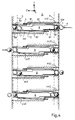
- Figure 3 is a longitudinal section of an embodiment of the connection block included in the device in accordance with the invention,
- Figure 4 illustrates another embodiment of the connection block included in the device in accordance with the invention in the same longitudinal section;
- Figures 5a-b illustrate an implementation of a y conductor included in the connection block according to Figures 3 or 4,
- Figure 7 illustrates an x conductor and a y conductor at a connection point in the block according to Figures 3 or 4,
- Figure 8 is a perspective view of a further embodiment of the connection block included in the device in accordance with the invention,
- Figures 9-10 are two different views of details in the connection block according to Figure 8,
- Figures 11-12 are cross sections in more detail of a part of the connection block according to Figures 3 or 4, and the operation block of the device in accordance with the invention,
- Figure 13 illustrates a lifting plate included in the operation block according to Figures 11-12,
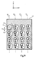
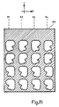
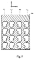
- Figures 14-17 illustrate different combination plates included in the operating block,
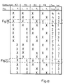
- Figure 18 is a table of combination possibilities,
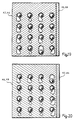
- Figures 19-20 illustrate two different combinations with the aid of the plates according to Figures 14-17.
- The switching device in accordance with the invention has two functions, namely a contact function in the contact part K and an operating function in the operating parts M1, M2 in the total operation block B. There are no electronic details included in these parts, and the switching and operating functions are carried out entirely mechanically under the action of solenoids. The function of the electromagnetic power transmission will not be described in detail, since this is not new and can be carried out with known technique.
- The connection block K, which provides the contact function contains a plurality of cavities, which will be described later in connection with Figures 2-4, in which balls are placed for providing contact between a plurality of incoming conductor pairs and a plurality of outgoing conductor pairs. The incoming conductor pairs are denoted x conductors, i.e. conductors in the x direction, and each pair comprises an a and a b conductor. The outgoing conductor pairs are denoted y conductors, i.e. conductors in the y direction, and similarly comprise an a and a b conductor. The different conductors are arranged with the same spacing as the pins in the cable means to which the device is connected, and can be directly connected, wound or soldered in a printed circuit board according to known principles. The conductors in the x and y directions are here illustrated as wires in the block K, but in practice are made in the form of ribbons placed in grooves or holes in an electrically insulating material. For example, the carcass of the block K can be of plastics, and the conductors are arranged so that a given spacing is kept between the y and x planes in the z direction. The block K therefore comprises two side members and an intermediate member, the side members having the mentioned grooves for the conductors and the intermediate member the cavities.
- Figure 2 illustrates more closely in a perspective view the connection block K and operation blocks M1, M2 with their different plates placed or arranged symmetrically on either side of the connection block K.
- As previously mentioned, the connection block K has a plurality of cavities which is equal to half the number of y conductors, i.e. the number of a or b conductors in the Y direction. Each cavity extends from one side surface of the block K to the opposite side surface, and the openings on the right hand side surface of the block K can be seen from Figure 2. As will be described in detail in connection with Figures 3 and 4, there are two pairs of balls arranged in, and in the vicinity of, each cavity for carrying out the contact function between an x conductor pair and a y conductor pair.
- The operation block comprises two identical operating parts M1 and M2, one on either side of the connection block K. The part M1 comprises from the left in figure 2 of:
a pin plate S1 provided with a plurality of pins which is equal to the number of cavities in the block K, for actuating the movement of the balls into associated cavities. The pin plate S1 can therefore be moved or displaced sideways according to the arrow;
an exterior lifting plate L1 provided with a plurality of elongate circularly rounded holes where the number of holes is equal to the number of pins in the pin plate S1. The lifting plate L1 can be moved or displaced in height according to the arrow;
a number of combination plates (three in Figure 2), K1, K3, K5, with specially shaped openings for forming one or several selected openings for one or several pins in a direction towards one or more balls, with the object of moving it or these in the associated cavity. These plates, the positions of which determine which ball(s) which is (are) to be moved are displaceable sideways and in height according to the arrows, and finally
an inner lifting plate L3 which, as with the lifting plate L1, is provided with the same number of circularly rounded off elongate holes and is displaceable synchronously with the lifting plate L1. - The elongate openings on the lifting plates L1, L3 and the openings of the combination plates K1-K3 are formed and placed in relation to each other such that when the pin plate S1 is moved in towards the connection block K an opening is always available for each pin on the pin plate. Each pin on the plate S1 will be able to move freely when the plate is displaced, but certain selected pin (or only one pin) will knock against the ball to displace it into, or in, the cavity itself.
- The operation means M2 comprises the same number of plates and is of the same embodiment as the operation means M1. The plates L2, L4 thus correspond to the plates L1 and L3, and the combination plates K2, K4, K6 correspond to the combination plates K1, K3, K5. A ball has also been illustrated in Figure 2 in front of the cavity in
row 1,column 1, which is kept in position by the lifting plates L2, L4 and where the combination plates K1, K4, K6 have a position such that a pin in the corresponding position on the pin plate S2 has a free path through these plates for enabling it to thrust the ball into the cavity, as will be described below. - Figure 3 is a cross section in the yz plane of an embodiment of the connection block K for a complete two-wire function, e.g. the four first rows in the first column according to Figure 2. For each row in a column there is a cavity H1, H2, H3 and H4.
- In the cavity H1 there is thus a first and a
second ball ball 1 is electrically conductive andball 2 is electrically non-conductive. In the illustrated position theball 1 rests on twometal tongues leaf spring 61 thrusts out in the z direction from anx conductor 6 which, as with they conductor 5, is molded into the block K except in the cavity itself. Theconductive ball 1 makes contact with an outwardlybent tongue part 61a of thespring 61. - At the other side of the cavity there is a
conductive ball 3, resting on twometal tongues 81, 82 of they conductor 8. Aleaf spring 71 is bent, linke thespring 61, to atongue portion 71a, which engages against theball 3. Thesecond ball 4 in this pair is outside the cavity H1 and is kept in the illustrated position with the aid of the lifting plates L2, L4 according to Figure 2. The displacement of theball 4 is achieved by arod 9 having a length and being disposed such that when one pair ofballs - The cavities H2, H3 and H4 are of the same implementation, and the same reference characters have been used. In the cavity H2 the ball 4 (non-conductive) is urged into the cavity by a pin in the corresponding position on the pin plate S2. In this way the
ball 3,rod 9 andball 2 have been displaced to the left in the Figure, so that theball 1 has now come outside the cavity H2 and is kept in position with the aid of the lifting plates L1, L3. The possible effect of the combination plates K1-K5 lying between the plates L1 and L3 is disregarded for the moment. - Conductive contact between incoming and departing conductor pairs is thus established in the cavities H1 and H3, while non-conductive contact is established in the cavities H2 and H4. Closing or opening thus takes place by moving in a conductive or non-conductive ball between the x and the
y conductors x conductor 61, 71 (which is bent beforehand) between two balls without the x conductor being moved up and down more than the tolerances that are between the balls and the shape of the x conductors. A large contact pressure can be built up in this way with very short springs. In addition, a large air gap can be obtained in the OFF position without movement of the spring on the x conductor. The air gap will be equal to the diameter of the non-conductive ball The force required to move the balls sideways is the frictional force. It should also be noted that the contact points of the ball and the points on the contacts which break contact are not the same. - The advantage with this is that if there is spark formation on opening, the contact surfaces on the x and y conductors are not affected. It should be further understood that it is improbable that the position of the ball on contact will be the same after an operation, i e. new contact points are utilized in each operation, which should give increased life to the contact function in relation to conventional relays.
- Four conceivable placings of the balls are illustrated in Figure 3. With the different placings; OFF or ON can be arranged either from the left or the right, with the aid of the left or the right pin plate S1 or S2. In addition, a switching change is obtained simultaneously by moving two contacts. By maneuvering the
balls 1 in the cavities H2 and H3 simultaneously, a switching is obtained between two x conductors towards one y conductor. This possibility can be used for accelerating certain functions, since several simultaneous operations can take place. - It should be noted that according to Figure 3 there is always one ball within the operating function. In the contact function it will do with three balls instead of the four illustrated in Figure 3. The
rod 9 can then be replaced by a ball, but for the sake of symmetry all four balls 1-4 have been shown. These can also be obtained with very great precision with regard to their diameters. - In Figure 4 there is illustrated a second embodiment of the cavities in the connection block K. In this embodiment each cavity comprises two hollow parts, the positions of which have been displaced in the y direction relative each other. The upper cavity in Figure 4, corresponding to the cavity H1 in Figure 3, comprises the hollow parts H11 and H12. The cavity part H11 is displaced a distance relative the cavity part H2, or vice versa, at most equal to the diameter of a ball. The
rod 9 has also been modified so that it now comprises twoend portions balls central portion 93. The leaf springs 62, 72 from therespective x conductors rod 9. The contact surfaces for thewire conductors single tongue contact tongues balls - The embodiment according to Figure 4 is advantageous, since the
leaf springs rod 9, which can thus be made shorter. As a result of this the width of the connection block K can be decreased. - Figures 5a-5c illustrate more closely an y conductor, where the Figures 5b, 5c illustrate two different embodiments of the contact surfaces against a ball. The conductor itself comprises a
ribbon 5 extending in the y direction in a groove inside the block K. Tongue-like projections forming the contact surfaces have been made by stamping and bending out "tongues" from theribbon 5. Figure 5a illustates the ribbon in the z direction, i.e. in towards the "hole side" of the connection block. Eachtongue 52 corresponds to a level in the y direction, i.e.level 1 is in the cavity H1 (according to Figure 3),level 2 is in the cavity H2 etc. - In the same view as Figures 3 and 4, Figure 5b illustrates an embodiment of the y conductor where the contact surfaces each comprise two
tongues single tongue 54 withprotuberances ball 1 which is in the contact position. - Figure 6 illustrates an embodiment of the x conductors for the a and b wires. Each x conductor comprises a
ribbon ribbons tongues 71, where the spacing between twotongues tongue parts - Figure 8 is a perspective view of a further embodiment of the connection block K. In this case the block comprises three parts K1, K2, K3 of which one part K1 is illustrated in Figure 8. The parts K1 and K3 comprise outer parts where the part K3 is not shown but is of the same embodiment as the part K1 but mounted to opposite hand in relation to it on assembly. The part K2 (the cross section which is apparent from Figure 10) constitutes the central part and is joined to both outer parts K1, K3. Figure 10 illustrates more closely how the parts are put together.
- Figure 8 also illustrates the appearance of a cavity in the part K1 but remaining cavities have the same appearance in principle. The cavity comprises partly the space formed between two projecting portions P1 and P2 and partly of a first and a second recess J1 and J2 formed in both portions P1 and P2. The recesses J1 and J2 are thus immediately opposite each other in the y direction of the connection block.
- In the wall V between both the projecting portions P1 and P2 there is a circular opening C, the diameter of which is somewhat larger than the diameter of a ball. The opening C is situated so that its central point lies opposite the lines of symmetry of both recesses.
- In the space between both portions P1 and P2 there are two wires w1 and w2 arranged so that they extend along the longitudinal direction (the x direction) of the space. The wire w1 can engage against the supports E1 and E2, which are fixedly arranged in the upper wall of the space. In a similar way the wire w2 engages against the supports E3 and E4, which are rigidly arranged in the low wall of the space. The wire pair w1 and w2 are suitably fixed to unillustrated pins arranged along each end surface of the part K1, so that the wires movably engage against the respective support. The wire pair w1 and w2 thus form the a wires in the x direction, while corresponding wire pairs in the other, unillustrated and mirrored part K3 form the b wires in the x direction.
- In a similar way, a wire pair w3 and w4 are arranged in the y direction. The wire w3 engages against fixed supports D1, D3 in one side wall of the recess J1 and J2, respectively, and the wire w4 engages against fixed supports D2, D4 in the opposing side wall of the recess J1, J2. Both wires w3, w4, as with the wires w1 and w2 rigidly clamped with the aid of pins to the end surfaces (not illustrated here) of the connection part K1. If the width of both recesses is equal to the height of the space between the both projecting portions P1 and P2, the wires w1, w2 and w3, w4 will form a substantially quadratic "window" in front of the opening C. However, the wire pair w1, w2 is displaced in the z direction relative the wire pair w3, w4, since both wire pairs shall not make contact with each other if there is no ball between the opening C and the wire pair. In Figure 8 a
ball 5 is illustrated, and this ball has been thrust in via the opening C and has assumed a position between the inner mouth of the opening at the wall V and one wire pair w1, w2. - Figure 9 is a view in the z direction of the connection block part K1. Both wire pairs w1, w2 and w3, w4 engage against their supports E1-E4 and D1-D4. The
ball 5 has been moved so that it has moved the wire pair w1, w2 (which engages against theball 5 behind it) away. The wire pair w3, w4 engages against the ball S in front of it. The ball S has thus been moved so that it no longer engages against the circular inner edge of the opening C, but is retained by the wires w1-w4 and is just about to penetrate into the opening of the central part K2 (which will be seen from Figure 10). - Figure 10 is a view from above in the y direction according to Figure 8, with four balls 1-4. In this Figure will be seen the position of the three parts K1-K3 of the connection block K, these parts engaging tightly against each other in their respective xy planes. The part K2 is provided with circular openings, of which one is illustrated in Figure 10, and which has the same diameter as the opening C in the parts K1, K3.
- A
ball 1 is illustrated in Figure 10, this ball having been moved under the action of a pin on the above-described pin plate a distance into the opening C1 (corresponding to the opening C in Figure 8) and has thus displaced theball 2. This ball was in the position according to Figure 8, i.e. between the wire "window" w1-w4 and the inner edge of the opening C1, before it was indirectly acted on by the pin via theball 1 to locate this position. In turn theball 2 has displaced theball 3 from its position inside the cavity C2 against the wires w7-w8 in the "wire-window" w5, 6w, w7, w8 and theball 3 has displaced theball 4 from these wires and out through the opening C3. - It is assumed that the
ball 1 and theball 3 are electrically conductive, while theball 2 andball 4 are electrically non-conductive. Furthermore the wire pairs are denoted as follows:

- In the initial position the
ball 1 lies entirely outside the block K1,ball 2 makes contact with ax, ay, theball 3 is entirely in the cavity C2 and theball 4 makes contact with bx, by. - On being acted on by the pin, the
ball 1 will establish conductive contact between ax and ay, theball 2 will be displaced into the opening in the cavity C2, theball 3 will establish conductive contact between bx and by and theball 4 will come outside the opening C3. There is thus obtained a two-pole closure or connection of the a and b conductors. When the pin acts on theball 4 in the opposite dirction (dashed arrow) there is obained a two-pole opening or interruption. - The Figures 11 and 12 illustrate, in the same cross sectional view as Figures 3 and 4, the right-hand part of the connection block K and the plates in the operating part which are to the right of the connection block. The details of the connection block have the same characters as in Figures 3 and 4 and the different plates in the operation means have the same characters as in Figure 2.
- Figure 11 illustrates an initial position with a
non-conductive ball 3 in contact with the twocontact surfaces ball 4. - In the position according to Figure 11 the lifting plates L2, L4 are in their upper position and have raised the
ball 4. The position of the pin plate in the z direction is such that the pin S12 is to the right of the support T1. This is the initial position for the crossbar switch in its entiety. Here theball 4 bears against both innter downward edges of the openings in the lifting plates L2, L4. The positions of the combination plates K3, K4, K6 and K8 in the x direction can now be set. - In the position according to Figure 12, the lifting plates L2, L4 have been lowered in the y direction when the combination plates K2, K4, K6 andK8 have assumed their positions, and it is assumed that, switching from non-conductive to conductive state is to be carried out for the cavity H4 (or H41). The combination plates K2-K8 thus form an opening in the z direction (c.f. Figures 19-20) of sufficient size for the
ball 4 to fall down and assume the lower position according to Figure 12. After this operation, the pin S12 can be moved in the z direction after actuation of the pin plate S2, such as to move theball 4 towards theball 3. When the pin is moved theball 4 will displace theball 3 so that the latter glides or possibly rolls out of its contact position according to Figure 11, and theball 3 now assumes this position and conductive contact is established. Theball 3 will thus move therod 9 as previously described. - For a given operating combination of the combination plates K2-K8 enabling these to be moved or not moved in the x direction, an opening for one or more balls will be formed so that one or more pins on the pin plate S1 and S2 can move the ball or balls to achieve contact changes. These combinations of the combination plates are more closely apparent from the Figures 14-15, 19-20.
- Figure 13 illustrates a lifting plate, e g. L2, seen directly from the front (the z direction). In this case the plate L2 has sixteen openings 11-14, 21-24, 31-34 and 41-44, arranged in four rows and four columns, with the openings in each column symmetrical about the respective axis of symmetry a₁, a₂, a₃ and a₄. Each of the openings 11-14, 21-24, 31-34 and 41-44 shall, together with corresponding openings in the lifting plate L4, serve as fixation and support for the balls which are outside the respective cavity according to Figures 11-12. In Figure 13 only two balls K22 and K32 are illustrated, for the sake of simplicity, but the balls in remaining openings have the same position in the openings.
- The lifting plate L2 (as with the plate L4) is displaceable in the y direction. Figure 13 shows the upper position (position 1) of the plate according to Figure 11, when the balls K22 and K32 are kept in their upper positions. When the plate L2 is displaced downwards (in the negative y direction), the balls K22 and K32 can fall down so that they come into position " in front of the respective cavity according to Figure 12. However the ball K22 is prevented from falling down because of the setting of the combination plates.
- In a view from the front (the z direction) the Figures 14-17 show the four different combination plates K2, K4, K6 and K8 in the operation block described in connection with Figures 2, 8 and 9. The combination plates K1, K3, K5 and K7 on the other side of the connection block K are of the same appearance.
- According to Figure 14, the combination plate K2 lying closest to the lifting plate L2 has sixteen openings 11-14, 21-24, 31-34 and 41-44 arranged in four rows and four columns. The number of the openings can of course be greater or less than shown here. Each opening, e.g. the opening 11 comprises an
elongate opening part 111 in the y direction, the dimension of this part being in substantial agreement with the dimension of an opening in the lifting plate L2, L4. In addition, the opening 11 is formed with an elongate upper andlower part part 112 has a width d₂, which is somewhat greater than the diameter of a pin on the pin plate S2 (see Figures 2 and 12). The distance d between twoopenings 11 and 12, i.e. the spacing, is equal to the spacing of the cavities and is the same as the spacing between the pins on the pin plate S2. - According to Figure 14 the openings 11-14 and 31-34 in the first and third rows are oriented to the right, i.e. the upper (wider)
part 112 and the lower (narrower)part 113 are directed to the right, while the openings 21-24 and 41-44 are oriented to the left. - The combination plate K2, as with remaining combination plates K4, K6 and K8 according to Figures 15-17, can be moved sideways (in the x direction) to form openings, so that a ball lifted by one of the lifting plates L2, L4 can fall down in front of a cavity. In Figure 14 the combination plate K2 is in its left position relative the symmetry axes a₁ - a₄. This results in that when the lifting plate L2 according to Figure 10 is thrust downwards all the balls in
rows row rows rows - The combination plate K4 according to Figure 12 has openings oriented such that the openings 11-14 and 21-24 in the first and second rows are oriented to the right, while the openings 31-34 and 41-44 in the third and fourth rows are oriented to the left.
- In Figures 16 and 17, the combination plates K6 and K8 have the openings in the columns with the same orientation. According to Figure 16, the plate K6 has its openings in the
columns columns columns columns - By moving the combination plates to the left or right in the x direction in relation to each other, openings corresponding to the
opening port 111 in Figure 14 can be formed, in each of which a ball can fall down in front of the associated cavity. There is described below, as an example, both the cases where only one, two, three or all combination plates K2, K4, K6 and K8 assume their left and respective right end positions. - Plate K2 by itself: All balls in
rows
Plates K2 and K4: All balls inrow 4 fall down.
Plates K2, K4 and K6: Balls inrow 4,columns
Plates K2, K4, K6 and K8: Only the ball inrow 4,column 4 falls down. - Plate K2 by itself: all balls in
rows
Plates K2 and K4: All balls inrow 1 fall down.
Plates K2, K4 and K6: The balls inrow 1columns
Plates K2, K4 K6 and K8: The ball inrow 1column 1 falls down. - The table according to Figure 18 illustrates all the combinations of the plate positions for obtaining that a ball in any column or row can fall down ("free ball"). When four plates K2, K4, K6 and K8 are used, where each plate has sixteen combination openings, blockage is obtained for all balls except the one selected. By selecting only three plates two balls in any row a column can be caused to fall down and thus obtain contact for two separate connections.
- Figures 19 and 20 are views from one side of the positions of the combination plates for two different cases according to the table in Figure 18.
- The opening 11 in the combination plate K2 according to Figure 14 can be replaced with an oval, symmetrical opening of the same shape as the openings of the lifting plates L1, L2, but with a height equal to the height of the opening 11 and with a width equal to the greatest width of the opening 11. Here the ball having a position corresponding to the opening 11 (now oval) will fall down in front of the associated cavity irrespective of what combination remaining plates K4-K8 are placed in. This enables obtaining a conductive (or non-conductive) contact at an intersection point simultaneously with contact in one of the remaining intersection points, independent of its position in the connection matrix. This possibility is of great value in telephony connections, since a switching function can be easily obtained in this way.
Claims (10)
- Galvanic switching device for achieving making, breaking or switching between a plurality of first conductor pairs (x, a, b) and the same number of second conductor pairs (y, a, b) which form a plurality of cross points in each of a connection matrix, where each cross point comprises a first and a second contact surface, the device including a connection unit (K) containing said cross points and control means (M) for controlling making or breaking at said cross points, characterized in that the connection block (K) comprises a solid, preferably rectangular block in which a plurality of cavities (H1, H2; H11, H12; C1-C3) are disposed from one side of the block to its opposite side, such as to correspond to the number of conductor pairs (x, a, b; y, a, b), in that in each cavity first pairs of spring contact surfaces (61a, 71a; 62a, 72a; w1, w2, w5, w6) for the first conductor pair (x, a, b) and second pairs of spring or fixed contact surfaces (51, 52; 81, 82, 52, 83; w3, w4, w7, w8) for the second conductor pair (y, a, b) are arranged on either side of the symmetrical axis of the cavity, in that a first and a second pair of spherical connection elements (1, 2 and 3, 4) are movably arranged in, and in the vicinity of, the cavity (H1; H11, H12; C1-C3) such that one connection element (1) in the pair (1, 2) can achieve electrically conductive contact when moved, and in that the second element (2) in the same pair achieves electrically non-conductive contact between said first and second contact surfaces for the first and second conductor pairs (x,a,b; y,a,b) in activating the unit (K) from said control means (M), in that means (9; 2,3) are disposed in the cavity (H1) so that for movement of the connection elements in one pair (1, 2) both connection elements in the second pair (3,4) are moved, and in that the control means (M) comprises a first and a second lifting plate (L1, L3 and L2, L4) disposed closest adjacent and parallel to the side surfaces of the unit (K) for moving, when being acutated, one (4) of said connection elements associated with each of said cavities parallel to the side surface of the unit to a first position in front of the opening of the associated cavity; a plurality of combination plates (K1-K6) placed between said first and second lifting plates on either side of the connection unit (K), which are adapted for being displaced in a direction parallel to the side surfaces of the unit, but at right angles to the movement of the lifting plates (L1, L3 and L2, L4), to form an opening to a given connection element so that on activation of a plurality of actuating elements (S1, S2) the selected connection element in a pair is moved in towards the second connection element in the pair, whereby said electrically conductive or non-conductive contact is achieved.
- Switching device as claimed in claim 1, characterized in that said means arranged in the cavity (H1; H11, H12) comprise a rod-like element (9), extending from the inner connection element (2) in one pair (1, 2) to the inner connection element (3) in the second pair (3, 4).
- Switching element as claimed in claim 1, characterized in that said means arranged in the cavity (c1-c3) comprise the inner connection element (2) in one pair (1, 2) and the inner connection element (3) in the other pair (3, 4)
- Switching element as claimed in claim 3, characterized in that said first spring contact surfaces comprise wire pairs (w1, w2; w3, w4) corresponding to said first conductor pairs (x, a, b) which are arranged in one longitudinal direction (the x direction) in the connection unit (K), and symmetrically in the cavity (c1-c3), and in that said second pair of spring contact surfaces comprise wire pairs (w3, w4; w7, w8) corresponding to said second conductor pairs (y,a,b) arranged in the other longitudinal direction of the connection unit (the y direction), perpendicular to said first wire pairs (w1,w2; w5,w6) and symmetrically in the cavity, such that one wire pair (w1,w2) in one longitudinal direction (x), together with a wire pair (w3, w4) in the other longitudinal direction, forms a substantially quadratic window in front of an opening (c) to a cavity (c1-c3), the dimension of which is selected slightly less than the mean dimension of a spherical element (1-4).
- Switching device as claimed in claim 2, characterized in that said cavity comprises a first cylindrical hole (H-1) from one side surface of the block, and of a second cylindrical hole (H11, H12, Figure 4) from the other side surface of the block, both cylindrical holes extending a distance into the block at right angles to the side surfaces and past its symmetrical axis so that the centre liners of the holes are in the same plane but are displaced at most one hole diameter in relation to each other.
- Switching device as claimed in claim 2, characterized in that the first conductor pair (x,a,b) comprises a plurality of parallel ribbons (7) fixedly arranged in the transverse direction (x) of the unit, and level with each cavity, where each ribbon is provided with a plurality of tongues (61, 71), each of which thrusts out into the respective cavity to form said spring element.
- Switching device as claimed in claims 5-6, characterized in that the second conductor pair (y,a,b) comprises a plurality of parallel ribbons (5) inside the unit and fixedly arranged in the longitudinal direction thereof, where each ribbon is provided with tongues (51, 52, 54) projecting out in the transverse direction of the unit, said tongues being fixedly arranged at the upper surface of the one cylindrical hole (H11) and at the opposing downward surface of the second cylindrical hole (H12) to form said fixed contact surfaces (51, 52, 81, 82).
- Switching device as claimed in claim 2, characterized in that said spherical connection elements (1,2,3,4) consist of balls with a diameter suited to the diameter of the cylindrical cavity, the movement transmitting element (9) being so dimensioned that when one pair of balls (1, 2) is entirely within said first cavity (H1) in the vicinity of its opening, one ball (4) of the other pair of balls (3, 4) is outside the cavity (H1).
- Switching device as claimed in claims 3 - 4, characterized in that said spherical connection elements (1-4) consist of balls, and in that said cavities comprise circular cylindrical holes (c) in the transverse direction of the connection unit the diameter of said holes being slightly greater than that of the balls.
- Switching device as claimed in claims 1-9, characterized in that said actuating element comprises a first and a second plate (S1, S2) with a plurality of pins corresponding to the number of openings of said cavities (H1-H2) said pins being mounted on the first and the second plate on either side of the connection unit (K) and parallel to said lifting plates (L1, L2) for enabling the movement of a given connection element (4) in a given pair of connection elements at right angles to said lifting plates.
Applications Claiming Priority (3)
| Application Number | Priority Date | Filing Date | Title |
|---|---|---|---|
| SE8703521A SE458891B (en) | 1987-09-10 | 1987-09-10 | GALVANIC CLUTCH DEVICE |
| SE8703521 | 1987-09-10 | ||
| PCT/SE1988/000452 WO1989002650A1 (en) | 1987-09-10 | 1988-09-02 | Galvanic switching device |
Publications (2)
| Publication Number | Publication Date |
|---|---|
| EP0331703A1 EP0331703A1 (en) | 1989-09-13 |
| EP0331703B1 true EP0331703B1 (en) | 1994-08-10 |
Family
ID=20369539
Family Applications (1)
| Application Number | Title | Priority Date | Filing Date |
|---|---|---|---|
| EP88907834A Expired - Lifetime EP0331703B1 (en) | 1987-09-10 | 1988-09-02 | Galvanic switching device |
Country Status (6)
| Country | Link |
|---|---|
| US (1) | US4954674A (en) |
| EP (1) | EP0331703B1 (en) |
| BR (1) | BR8807199A (en) |
| DE (1) | DE3851051T2 (en) |
| SE (1) | SE458891B (en) |
| WO (1) | WO1989002650A1 (en) |
Families Citing this family (4)
| Publication number | Priority date | Publication date | Assignee | Title |
|---|---|---|---|---|
| SE468693B (en) * | 1991-06-17 | 1993-03-01 | Ericsson Telefon Ab L M | GALVANIC CLUTCH DEVICE |
| SE515404C2 (en) * | 1995-08-04 | 2001-07-30 | Ericsson Telefon Ab L M | Switching System |
| SE9502753L (en) * | 1995-08-04 | 1997-02-05 | Ericsson Telefon Ab L M | Matrix structured cross-coupling arrangement |
| US6710268B2 (en) * | 2000-11-03 | 2004-03-23 | Telefonaktiebolagot Lm Ericsson (Publ) | Device for matrix switching |
Family Cites Families (5)
| Publication number | Priority date | Publication date | Assignee | Title |
|---|---|---|---|---|
| US2647166A (en) * | 1949-01-19 | 1953-07-28 | Int Standard Electric Corp | Switching mechanism |
| FR1194402A (en) * | 1957-01-29 | 1959-11-09 | Large number of direction selector relay | |
| US2997557A (en) * | 1959-04-06 | 1961-08-22 | Gordon W Wholey | Inertia switch |
| US3354434A (en) * | 1964-01-17 | 1967-11-21 | Jr Bernard Edward Shlesinger | Circuit programming system and method |
| DE3313937A1 (en) * | 1983-04-15 | 1984-10-18 | CREATEC Gesellschaft für Elektrotechnik mbH, 1000 Berlin | ELECTRIC SWITCH |
-
1987
- 1987-09-10 SE SE8703521A patent/SE458891B/en not_active IP Right Cessation
-
1988
- 1988-09-02 WO PCT/SE1988/000452 patent/WO1989002650A1/en not_active Ceased
- 1988-09-02 DE DE3851051T patent/DE3851051T2/en not_active Expired - Fee Related
- 1988-09-02 BR BR888807199A patent/BR8807199A/en not_active IP Right Cessation
- 1988-09-02 US US07/354,432 patent/US4954674A/en not_active Expired - Lifetime
- 1988-09-02 EP EP88907834A patent/EP0331703B1/en not_active Expired - Lifetime
Also Published As
| Publication number | Publication date |
|---|---|
| SE8703521D0 (en) | 1987-09-10 |
| BR8807199A (en) | 1989-10-17 |
| US4954674A (en) | 1990-09-04 |
| SE8703521L (en) | 1989-03-11 |
| DE3851051D1 (en) | 1994-09-15 |
| EP0331703A1 (en) | 1989-09-13 |
| WO1989002650A1 (en) | 1989-03-23 |
| SE458891B (en) | 1989-05-16 |
| DE3851051T2 (en) | 1994-12-01 |
Similar Documents
| Publication | Publication Date | Title |
|---|---|---|
| US5432847A (en) | Low frequency telecommunication digital network interface patch panel | |
| US4695117A (en) | Jack module and jackfield | |
| US4954674A (en) | Matrix crosspoint switching device | |
| US4286121A (en) | Telephone line cutover apparatus and switch | |
| US4655535A (en) | Jack module and jackfield | |
| EP0179067B1 (en) | Air-line microwave coaxial reversing switch | |
| CA1232310A (en) | Switch apparatus | |
| CA1293073C (en) | Galvanic switching device | |
| AU611203B2 (en) | A crossbar switching device | |
| EP0603161A2 (en) | Zero insertion force connector for cable to board applications | |
| US4421965A (en) | Commutator with several layers of cross-points | |
| AU705125B2 (en) | Coupling arrangement | |
| GB2263591A (en) | Impedance-matched switched co-axial interconnector | |
| US4086546A (en) | Universal attenuator | |
| EP0197234B1 (en) | Electrical connector module with multiple connector housings | |
| JP3458348B2 (en) | Connection pin | |
| US4692578A (en) | Universal matrix switching device | |
| US20060001510A1 (en) | High isolation rf switch | |
| EP0842523B1 (en) | Matrix-related jumpering arrangement | |
| US3643053A (en) | Crossbar switch with prestressed mobile contact spring and perpendicular first and second shifting means | |
| US2415437A (en) | Telephone exchange apparatus | |
| US6712628B2 (en) | Connector/switch unit for a flat antenna | |
| KR200313675Y1 (en) | A RF switch having the improved electromagnet | |
| EP0265124A2 (en) | Electrical connector | |
| WO2008101795A1 (en) | System, sheet and method for isolating a contact element from a contact pad in a switch matrix |
Legal Events
| Date | Code | Title | Description |
|---|---|---|---|
| PUAI | Public reference made under article 153(3) epc to a published international application that has entered the european phase |
Free format text: ORIGINAL CODE: 0009012 |
|
| 17P | Request for examination filed |
Effective date: 19890418 |
|
| AK | Designated contracting states |
Kind code of ref document: A1 Designated state(s): AT BE CH DE FR GB IT LI LU NL SE |
|
| RBV | Designated contracting states (corrected) |
Designated state(s): BE DE FR GB IT NL SE |
|
| 17Q | First examination report despatched |
Effective date: 19940125 |
|
| GRAA | (expected) grant |
Free format text: ORIGINAL CODE: 0009210 |
|
| AK | Designated contracting states |
Kind code of ref document: B1 Designated state(s): BE DE FR GB IT NL SE |
|
| ET | Fr: translation filed | ||
| REF | Corresponds to: |
Ref document number: 3851051 Country of ref document: DE Date of ref document: 19940915 |
|
| ITF | It: translation for a ep patent filed | ||
| PG25 | Lapsed in a contracting state [announced via postgrant information from national office to epo] |
Ref country code: SE Effective date: 19941110 |
|
| PLBE | No opposition filed within time limit |
Free format text: ORIGINAL CODE: 0009261 |
|
| STAA | Information on the status of an ep patent application or granted ep patent |
Free format text: STATUS: NO OPPOSITION FILED WITHIN TIME LIMIT |
|
| 26N | No opposition filed | ||
| PGFP | Annual fee paid to national office [announced via postgrant information from national office to epo] |
Ref country code: BE Payment date: 19980914 Year of fee payment: 11 |
|
| PG25 | Lapsed in a contracting state [announced via postgrant information from national office to epo] |
Ref country code: BE Free format text: LAPSE BECAUSE OF NON-PAYMENT OF DUE FEES Effective date: 19990930 |
|
| BERE | Be: lapsed |
Owner name: TELEFONAKTIEBOLAGET L M ERICSSON Effective date: 19990930 |
|
| PGFP | Annual fee paid to national office [announced via postgrant information from national office to epo] |
Ref country code: NL Payment date: 20000824 Year of fee payment: 13 |
|
| REG | Reference to a national code |
Ref country code: GB Ref legal event code: IF02 |
|
| PG25 | Lapsed in a contracting state [announced via postgrant information from national office to epo] |
Ref country code: NL Free format text: LAPSE BECAUSE OF NON-PAYMENT OF DUE FEES Effective date: 20020401 |
|
| NLV4 | Nl: lapsed or anulled due to non-payment of the annual fee |
Effective date: 20020401 |
|
| PGFP | Annual fee paid to national office [announced via postgrant information from national office to epo] |
Ref country code: FR Payment date: 20020819 Year of fee payment: 15 |
|
| PGFP | Annual fee paid to national office [announced via postgrant information from national office to epo] |
Ref country code: GB Payment date: 20020828 Year of fee payment: 15 |
|
| PGFP | Annual fee paid to national office [announced via postgrant information from national office to epo] |
Ref country code: DE Payment date: 20020930 Year of fee payment: 15 |
|
| NLV4 | Nl: lapsed or anulled due to non-payment of the annual fee |
Effective date: 20020401 |
|
| PG25 | Lapsed in a contracting state [announced via postgrant information from national office to epo] |
Ref country code: GB Free format text: LAPSE BECAUSE OF NON-PAYMENT OF DUE FEES Effective date: 20030902 |
|
| PG25 | Lapsed in a contracting state [announced via postgrant information from national office to epo] |
Ref country code: DE Free format text: LAPSE BECAUSE OF NON-PAYMENT OF DUE FEES Effective date: 20040401 |
|
| GBPC | Gb: european patent ceased through non-payment of renewal fee | ||
| PG25 | Lapsed in a contracting state [announced via postgrant information from national office to epo] |
Ref country code: FR Free format text: LAPSE BECAUSE OF NON-PAYMENT OF DUE FEES Effective date: 20040528 |
|
| REG | Reference to a national code |
Ref country code: FR Ref legal event code: ST |
|
| PG25 | Lapsed in a contracting state [announced via postgrant information from national office to epo] |
Ref country code: IT Free format text: LAPSE BECAUSE OF NON-PAYMENT OF DUE FEES;WARNING: LAPSES OF ITALIAN PATENTS WITH EFFECTIVE DATE BEFORE 2007 MAY HAVE OCCURRED AT ANY TIME BEFORE 2007. THE CORRECT EFFECTIVE DATE MAY BE DIFFERENT FROM THE ONE RECORDED. Effective date: 20050902 |