EP0331585A2 - Method for deconvolution of unknown source signatures from unknown waveform data - Google Patents
Method for deconvolution of unknown source signatures from unknown waveform data Download PDFInfo
- Publication number
- EP0331585A2 EP0331585A2 EP89400617A EP89400617A EP0331585A2 EP 0331585 A2 EP0331585 A2 EP 0331585A2 EP 89400617 A EP89400617 A EP 89400617A EP 89400617 A EP89400617 A EP 89400617A EP 0331585 A2 EP0331585 A2 EP 0331585A2
- Authority
- EP
- European Patent Office
- Prior art keywords
- waveforms
- source
- time
- calculating
- signature
- Prior art date
- Legal status (The legal status is an assumption and is not a legal conclusion. Google has not performed a legal analysis and makes no representation as to the accuracy of the status listed.)
- Granted
Links
- 238000000034 method Methods 0.000 title claims abstract description 42
- 238000004458 analytical method Methods 0.000 claims abstract description 12
- 230000003213 activating effect Effects 0.000 claims 1
- 230000003993 interaction Effects 0.000 abstract description 4
- 238000012545 processing Methods 0.000 description 8
- 238000005553 drilling Methods 0.000 description 7
- 230000015572 biosynthetic process Effects 0.000 description 6
- 238000005755 formation reaction Methods 0.000 description 6
- 238000005259 measurement Methods 0.000 description 4
- 238000005303 weighing Methods 0.000 description 4
- 238000012937 correction Methods 0.000 description 3
- 230000000694 effects Effects 0.000 description 3
- 230000003044 adaptive effect Effects 0.000 description 2
- 238000013461 design Methods 0.000 description 2
- 238000001914 filtration Methods 0.000 description 2
- 230000005534 acoustic noise Effects 0.000 description 1
- 238000003491 array Methods 0.000 description 1
- 230000001934 delay Effects 0.000 description 1
- 230000001419 dependent effect Effects 0.000 description 1
- 238000013508 migration Methods 0.000 description 1
- 230000005012 migration Effects 0.000 description 1
- 230000000737 periodic effect Effects 0.000 description 1
- 230000001902 propagating effect Effects 0.000 description 1
- 238000000926 separation method Methods 0.000 description 1
- 230000003595 spectral effect Effects 0.000 description 1
- 238000001228 spectrum Methods 0.000 description 1
- 238000010561 standard procedure Methods 0.000 description 1
- 230000001360 synchronised effect Effects 0.000 description 1
Images

Classifications
-
- G—PHYSICS
- G01—MEASURING; TESTING
- G01V—GEOPHYSICS; GRAVITATIONAL MEASUREMENTS; DETECTING MASSES OR OBJECTS; TAGS
- G01V1/00—Seismology; Seismic or acoustic prospecting or detecting
- G01V1/28—Processing seismic data, e.g. analysis, for interpretation, for correction
- G01V1/36—Effecting static or dynamic corrections on records, e.g. correcting spread; Correlating seismic signals; Eliminating effects of unwanted energy
- G01V1/364—Seismic filtering
- G01V1/366—Seismic filtering by correlation of seismic signals
Definitions
- This invention relates to methods for processing of waveform data to profile the earth's subsurface structure in the vicinity of a borehole. More specifically, it relates to methods for estimation and removal of the effect of an unknown source signature by coherency analysis and data adaptive deconvolution filtering.
- Reflection seismology involves profiling subsurface earth formations to aid in resource prospecting. Seismic energy, in the form of acoustic waves, is generated by a source and coupled to the earth such that the waves travel through the subsurface formations. At each interface between different subsurface layers, a part of the incident acoustic wave is reflected towards one or more receivers, where the energy is recorded for subsequent analysis.
- the ultimate objective of seismic analysis is to determine the strengths and distribution of reflectors of seismic energy within the earth, such reflectors being intimately related to bedding geometry and differences in material properties.
- the determination of the distribution of reflecting strength within the earth requires an estimation of the wavefield incident on each reflector, since the reflected wavefield is the result of an interaction of the reflectors with the incident wavefield. This interaction is modeled as the convolution of the reflecting distribution and strengths with the incident wavefield.
- the sought properties of the reflectors are thus obtained by deconvolving the reflected wavefield by the incident wavefield. If the source is impulsive, the deconvolution is not necessary--if the source has an extended signature, knowledge of the signature enables the reduction to an impulsive signature.
- VSP vertical seismic profiling
- MWD measurement while drilling
- An alternative to using known sources downhole is to use the noise generated by the drill bit as it is drilling as a source of acoustic waves.
- This MWD method offers a source with uncontrolled characteristics, the signal depending on the design of the drill, the speed of rotation and on the properties of the material in the borehole. Furthermore, there is no starting time for such a signal, for the drill is continuously rotating.
- the two main problems with using the drill bit as a seismic source are thus the unknown signature of the drill bit noise and the timing of the data.
- the timing of the data is related to knowledge of the acoustic velocity of the subsurface formations between the drill bit and the receivers.
- a processing technique for independent determination and deconvolution of the signature of an unknown, non-impulsive acoustic source signal for seismic profiling, and the velocity of the medium in which the source is embedded.
- the method supposes that an array of receivers is positioned at the earth's surface to detect and record the seismic signals resulting from the interaction of such non-impulsive source with the earth's subsurface.
- the seismic signals are recorded as data traces at each receiver in the array.
- Moveout corrections which time-shift the data traces, correct for differences in the arrival times of a wavefront of the direct wave propagating from the source to the receivers in the array.
- the time-shifts are determined by a coherency analysis of the seismic data, wherein the time difference between the occurrence at adjacent traces of the dominant energy in any single trace, is determined. Since the dominant energy within any single trace is due to direct waves from the source, the moveout corrections synchronize the waveforms of the direct wave across the receiver array.
- the non-impulsive source signature is estimated as a weighted average of the signals from each time-shifted trace.
- the weighing factor to be applied to each single trace is estimated from a priori knowledge of the location of other sources contributing to the seismic energy recorded by the traces.
- the velocity of the medium between the source and the receiver arrays is determined from an analysis of the moveout time-shifts in relation to the geometry of the total ensemble of the source and the receivers. The velocity is used to fix the time reference of the data.
- the effect of the extended signature of the non-impulsive source on the seismic signals measured by the receiver array is removed by an inverse amplitude deconvolution filter, obtained from the estimate of the source signature.
- the filter in accordance with the invention, is weighted according to an analysis of the seismic data which, at any given frequency, indicates the strength of the unknown source relative to the total strength of the recorded seismic signal.
- the present invention describes how the two problems of signature and velocity estimations can be separated and the source signature be reduced to an impulsive signature for any variations of acoustic velocity, provided the drill bit is the strongest subsurface source of acoustic energy.
- This invention is particularly useful in seismic profiling when continuously emitting sources are used, in particular noise from the drill bit, but is also useful of other downhole acoustic sources with extended signature. Finally, it can be applied to waveform data other the seismic data, such as electromagnetic data generated from a downhole source with an extended time signature.
- FIG. 1 of the drawings a configuration for the implementation of a reverse VSP (RVSP) technique, using the drill bit 10 as a source of acoustic wave, is shown.
- the drill bit 10 is inserted into a borehole 12, which transverses the earth formation 18.
- An array of receivers 14 is positioned on the earth's surface to detect and record acoustic waves resulting from the source, reflected source wavefronts and random noise.
- the drill bit 10 acts as a source of acoustic waves while it is rotating.
- the signature of the noise generated by the drill bit is, however, unknown and uncontrolled, depending on the design of the bit, on its speed of rotation in the borehole 12 and on the materials in the borehole 12.
- the periodic motion of the tool generates a signal with a few strong spectral components, and the signature is by the nature of its generation non-impulsive.
- Hammering of the drill bit 10 against the bottom of the borehole 12 during drilling operations is a source of energy that widens the frequency spectrum of the drill bit signature. Due to the difficulties involved in having electric wires between the surface and the bottom of the borehole it is not at the present seen feasible to use devices downhole that measures the drill bit noise and transmits these measurements to the surface.
- FIG. 2 of the drawing a one dimensional array of receivers 20 is shown lying on the surface of the earth 22. To assure collection of sufficient data, the dimensions of the array 20 must be arranged such that its length, 1, satisfies the relationship:
- a one dimensional array is illustrated in the drawing, a grid or two dimensional array may be utilized, in which case the array should be dimensioned in any direction in accordance with the above requirements.
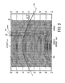
- Each vertical line 32 is called a "trace" and represents the variation with respect to time of the acoustic signal at a receiver 16 which is offset from the source 10 by the distance indicated.
- FIG. 4 of the drawings illustrates the different arrival times resulting from the geometry relating the position of the receiver array 14 and the drill bit 10 of FIG. 1.
- receivers 40, 42 and 44 are on the earth's surface above source 46, which is directly below receiver 42.
- a direct acoustic wavefront from the source 46 will reach receiver 42 before reaching receiver 40 and 44 since the path 50 is shorter than paths 48 or 52.
- the accoustic wave from source 46 will reach receiver 44 before receiver 40 because of the greater offset of receiver 40.
- the traces 32 associated with receivers 40 and 44 must therefore be time-shifted accordingly, so that the arrival times line up.
- the determination of the moveout corrections in accordance with the invention is done by performing local coherency analysis of the neighboring traces 32. If the direct acoustic wavefront 54 shown in FIG. 4 dominates the energy of the traces 32, i.e. is stronger than the wavefronts 56 reflected by an interface 57 of two different subsurface formation layers and noise from other sources, the coherency analysis enables the determination of the shape of the wavefront 54, and thereby the time-shifts that need to be applied to compensate for the differences in travel time from the source 46 to the individual receivers.
- the coherency analysis is implemented in the preferred embodiment by digitizing the analog recordings of the acoustic signals by means of high speed analog to digital converter circuits 45.
- the digital data is then multiplexed by multiplexer 46 to a standard high speed tape recorder 47 and to a processor 48.
- the processor 48 transforms the digitized data from the time domain to the frequency domain by means of a Fourier Transform, so that the trace 32 data are described as a function of offset, x, and frequency, w.
- the "slope", p, for a number of adjacent traces 36 is defined as the time shift 37, per unit of offset 39.
- a local slant stack, S(x m ,w,p), over the 2N + 1 traces 36 centered at offset xm, at slope p, and frequency w, is computed such that: where so(w) is the Fourier transform of the recorded acoustic signals at offset Xn and frequency w and g /wp/x - x is the Fourier Transform of an operator that shifts the traces in time according to a constant value of p.
- the local slant stack, S(x m ,w,p,), for each offset, xm, frequency, w, and slope, p, is determined.
- the energy of each stack is determined such that
- a measure of local coherency, E(xm,p) may be formed from the correlation of recorded acoustic signals from pairs of adjacent traces: where s m (w) denotes the complex conjugate of sm(w).
- the time shift at a particular offset xm related to the dominant source is determined by the stack containing the maximum energy at a particular offset.
- a function, p(xm) is defined to consist of the (xm,p)-values corresponding to maximum energy E(xm,p) for each offset xm.
- the function p( Xm ) is integrated to give the moveout, T m , to be applied to each offset:
- the minimum value of all the calculated T m -values is found and subtracted from the T m -values already calculated to give a new set of T m -values.
- This new set of Tm-values are the time delays that are used in the following calculation.
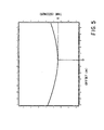
- the variation of T m with x m is illustrated in FIG. 5.
- the average velocity of the acoustic medium between source and receivers is determined by fitting a hyperbola to the moveout curve of FIG. 5:
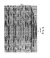
- the result of applying the time shifts, as determined from the moveout curve in FIG. 5, to the recorded data is shown in FIG. 6.
- the moveout corrected data represent a family of traces, each containing a copy of the source signature, which have been synchronized across all traces.
- the next step in the reduction is to apply a data adaptive deconvolution to reduce the extended signature of the drill bit 10 to an impulsive signature, starting at time t m :
- the best estimate of the signature is the spatial average of the moveout corrected traces: where s m (t + T m ) is the moveout corrected version of the trace measured at the offset x m , and M is the total number of traces.
- weights w m can be introduced into the estimation of f(t) to reduce the relative importance of the traces measured at offsets x m .
- the standard deconvolution filter may be designed by taking the inverse amplitude at each frequency and multiplying by the desired impulsive signature D(w): where f(w) is the complex conjugate of f(w), and is the inverse amplitude of f(w).
- the signature f(t) is the signature of a grinding drill bit.
- the signature f(t) and filer F" (w), are, therefore highly frequency dependent.
- the deconvolution filter therefore, in accordance with the present invention, includes a weighing based on the reliability of the different frequency amplitudes of the estimated signal.
- the weighing factor in the preferred embodiment of the invention, is obtained by taking the ratio of the energy of the average trace: to the average energy of the traces:
- the deconvolution filter then becomes:
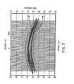
- Applying the filter F(w) to the moveout corrected data shown in FIG. 6 will transform the data into a dataset similar to a dataset that would have been collected if an impulsive source were used at the position of the drill bit, and the directly travelling and reflected waves were recorded at the offsets z m .
- the result of applying the filter to moveout corrected data is illustrated in FIG. 7, wherein the source signature 90 is reduced to an impulsive type source and the data from reflections 92 is reduced to that which would result from an impulsive source.
- This data can now be processed using standard processing techniques, such as common depth point (CDP) or migration.
- CDP common depth point
Abstract
Description
- This invention relates to methods for processing of waveform data to profile the earth's subsurface structure in the vicinity of a borehole. More specifically, it relates to methods for estimation and removal of the effect of an unknown source signature by coherency analysis and data adaptive deconvolution filtering.
- Reflection seismology involves profiling subsurface earth formations to aid in resource prospecting. Seismic energy, in the form of acoustic waves, is generated by a source and coupled to the earth such that the waves travel through the subsurface formations. At each interface between different subsurface layers, a part of the incident acoustic wave is reflected towards one or more receivers, where the energy is recorded for subsequent analysis.
- The ultimate objective of seismic analysis is to determine the strengths and distribution of reflectors of seismic energy within the earth, such reflectors being intimately related to bedding geometry and differences in material properties. The determination of the distribution of reflecting strength within the earth requires an estimation of the wavefield incident on each reflector, since the reflected wavefield is the result of an interaction of the reflectors with the incident wavefield. This interaction is modeled as the convolution of the reflecting distribution and strengths with the incident wavefield. The sought properties of the reflectors are thus obtained by deconvolving the reflected wavefield by the incident wavefield. If the source is impulsive, the deconvolution is not necessary--if the source has an extended signature, knowledge of the signature enables the reduction to an impulsive signature.
- Various configurations of acoustic sources and receivers are used to perform the seismic profiling. In vertical seismic profiling (VSP), the drilling operations are halted while receivers are lowered into the borehole. A source on the surface generates acoustic waves which are recorded at various levels by receiver in the borehole. More recently, VSP has been performed with the positions of the source and receiver reversed. The so-called reverse VSP (RVSP), utilizes an array of receivers at the surface and a downhole source. New methods in seismic profiling, called measurement while drilling (MWD), are directed towards performing seismic measurements without halting the drilling operations, thereby saving time and operating costs. Attempts have been made to develop sources with controllable characteristics for use in the borehole while drilling. The data acquired using such sources could be processed using existing processing techniques--they would, however, require additional electrical connections in the borehole and must be coupled efficiently to the earth formation to deliver the seismic energy into the subsurface. Both of these requirements may interfere with drilling.
- An alternative to using known sources downhole is to use the noise generated by the drill bit as it is drilling as a source of acoustic waves. This MWD method, however, offers a source with uncontrolled characteristics, the signal depending on the design of the drill, the speed of rotation and on the properties of the material in the borehole. Furthermore, there is no starting time for such a signal, for the drill is continuously rotating. The two main problems with using the drill bit as a seismic source are thus the unknown signature of the drill bit noise and the timing of the data. The timing of the data is related to knowledge of the acoustic velocity of the subsurface formations between the drill bit and the receivers.
- In accordance with the invention there is provided a processing technique, for independent determination and deconvolution of the signature of an unknown, non-impulsive acoustic source signal for seismic profiling, and the velocity of the medium in which the source is embedded. The method supposes that an array of receivers is positioned at the earth's surface to detect and record the seismic signals resulting from the interaction of such non-impulsive source with the earth's subsurface. The seismic signals are recorded as data traces at each receiver in the array.
- Moveout corrections, which time-shift the data traces, correct for differences in the arrival times of a wavefront of the direct wave propagating from the source to the receivers in the array. The time-shifts are determined by a coherency analysis of the seismic data, wherein the time difference between the occurrence at adjacent traces of the dominant energy in any single trace, is determined. Since the dominant energy within any single trace is due to direct waves from the source, the moveout corrections synchronize the waveforms of the direct wave across the receiver array. The non-impulsive source signature is estimated as a weighted average of the signals from each time-shifted trace. The weighing factor to be applied to each single trace is estimated from a priori knowledge of the location of other sources contributing to the seismic energy recorded by the traces.
- The velocity of the medium between the source and the receiver arrays, is determined from an analysis of the moveout time-shifts in relation to the geometry of the total ensemble of the source and the receivers. The velocity is used to fix the time reference of the data.
- The effect of the extended signature of the non-impulsive source on the seismic signals measured by the receiver array is removed by an inverse amplitude deconvolution filter, obtained from the estimate of the source signature. The filter, in accordance with the invention, is weighted according to an analysis of the seismic data which, at any given frequency, indicates the strength of the unknown source relative to the total strength of the recorded seismic signal.
- Once the effect of the acoustic source has been removed by the processing steps in accordance with the invention, standard processing techniques are used to analyze the processed seismic data to create an image. of the earth's subsurface.
- The present invention describes how the two problems of signature and velocity estimations can be separated and the source signature be reduced to an impulsive signature for any variations of acoustic velocity, provided the drill bit is the strongest subsurface source of acoustic energy.
- This invention is particularly useful in seismic profiling when continuously emitting sources are used, in particular noise from the drill bit, but is also useful of other downhole acoustic sources with extended signature. Finally, it can be applied to waveform data other the seismic data, such as electromagnetic data generated from a downhole source with an extended time signature.
-
- FIG. 1 illustrates a configuration for RVSP using an unknown and non-impulsive acoustic source and an array of receivers.
- FIG. 2 illustrates the dimension requirements of receiver array in accordance with the processing steps of the present invention.
- FIG. 3 illustrates traces of acoustic signals recorded at each receiver in an array.
- FIG. 4 illustrates the geometry of the RVSP configuration.
- FIG. 5 is the moveout curve that specifies the time-shifts to be applied to each trace of acoustic signals.
- FIG. 6 illustrates the moveout corrected data traces.
- FIG. 7 illustrates moveout corrected data after application of a deconvolution filter.
- Referring to FIG. 1 of the drawings, a configuration for the implementation of a reverse VSP (RVSP) technique, using the
drill bit 10 as a source of acoustic wave, is shown. Thedrill bit 10 is inserted into aborehole 12, which transverses theearth formation 18. An array ofreceivers 14 is positioned on the earth's surface to detect and record acoustic waves resulting from the source, reflected source wavefronts and random noise. - It is the purpose of the seismic method of exploration for resources to use the reflected acoustic energy to extract information about material properties of the subsurface. When a source with extended signature is used, waves travelling directly from the source to the receivers will overlap both in space and in time with energy reflected from different interfaces and arrive at the same time at the
receivers 16. In other types of seismic exploration where sources with extended signatures are used, measurements or a priori knowledge of the signature make it possible to reduce the recorded data to data that is similar to what would have been generated by an impulsive source. In doing this, the different wavefronts are separated in time. The technique used to perform this separation is deconvolution. - The
drill bit 10 acts as a source of acoustic waves while it is rotating. The signature of the noise generated by the drill bit is, however, unknown and uncontrolled, depending on the design of the bit, on its speed of rotation in theborehole 12 and on the materials in theborehole 12. The periodic motion of the tool generates a signal with a few strong spectral components, and the signature is by the nature of its generation non-impulsive. Hammering of thedrill bit 10 against the bottom of theborehole 12 during drilling operations, is a source of energy that widens the frequency spectrum of the drill bit signature. Due to the difficulties involved in having electric wires between the surface and the bottom of the borehole it is not at the present seen feasible to use devices downhole that measures the drill bit noise and transmits these measurements to the surface. This means that the signature of the drill bit noise is not readily available by any standard techniques. Referring to FIG. 2 of the drawing, a one dimensional array ofreceivers 20 is shown lying on the surface of theearth 22. To assure collection of sufficient data, the dimensions of thearray 20 must be arranged such that its length, 1, satisfies the relationship: - I! ?; 2d
- Additionally, the distance, s, between two
adjacent receivers - S <
- Although a one dimensional array is illustrated in the drawing, a grid or two dimensional array may be utilized, in which case the array should be dimensioned in any direction in accordance with the above requirements.
- Referring to FIG. 3 of the drawings, the acoustic signals recorded at each
receiver 16 in thearray 14 as a result of thedrill bit 10 rotation, are shown. Eachvertical line 32 is called a "trace" and represents the variation with respect to time of the acoustic signal at areceiver 16 which is offset from thesource 10 by the distance indicated. - FIG. 4 of the drawings illustrates the different arrival times resulting from the geometry relating the position of the
receiver array 14 and thedrill bit 10 of FIG. 1. Referring to FIG. 4receivers source 46, which is directly belowreceiver 42. As a result, a direct acoustic wavefront from thesource 46 will reachreceiver 42 before reachingreceiver path 50 is shorter thanpaths 48 or 52. Similarly, the accoustic wave fromsource 46 will reachreceiver 44 beforereceiver 40 because of the greater offset ofreceiver 40. Thetraces 32 associated withreceivers - The determination of the moveout corrections in accordance with the invention, is done by performing local coherency analysis of the neighboring traces 32. If the direct
acoustic wavefront 54 shown in FIG. 4 dominates the energy of thetraces 32, i.e. is stronger than thewavefronts 56 reflected by aninterface 57 of two different subsurface formation layers and noise from other sources, the coherency analysis enables the determination of the shape of thewavefront 54, and thereby the time-shifts that need to be applied to compensate for the differences in travel time from thesource 46 to the individual receivers. - The coherency analysis is implemented in the preferred embodiment by digitizing the analog recordings of the acoustic signals by means of high speed analog to
digital converter circuits 45. The digital data is then multiplexed bymultiplexer 46 to a standard high speed tape recorder 47 and to aprocessor 48. For ease of computation, theprocessor 48 transforms the digitized data from the time domain to the frequency domain by means of a Fourier Transform, so that thetrace 32 data are described as a function of offset, x, and frequency, w. - Referring to FIG. 3, the "slope", p, for a number of
adjacent traces 36 is defined as thetime shift 37, per unit of offset 39. A local slant stack, S(xm,w,p), over the 2N + 1 traces 36 centered at offset xm, at slope p, and frequency w, is computed such that:
- The energy of each stack is determined such that

- in a second embodiment of the invention, a measure of local coherency, E(xm,p), may be formed from the correlation of recorded acoustic signals from pairs of adjacent traces:

- The time shift at a particular offset xm related to the dominant source is determined by the stack containing the maximum energy at a particular offset. A function, p(xm), is defined to consist of the (xm,p)-values corresponding to maximum energy E(xm,p) for each offset xm. The function p(Xm) is integrated to give the moveout, Tm, to be applied to each offset:

- As the data has no absolute reference time, in the preferred embodiment of the invention, the minimum value of all the calculated Tm-values is found and subtracted from the Tm-values already calculated to give a new set of Tm-values. This new set of Tm-values are the time delays that are used in the following calculation. The variation of Tm with xm is illustrated in FIG. 5.
- To obtain an absolute time reference for the data, the average velocity of the acoustic medium between source and receivers is determined by fitting a hyperbola to the moveout curve of FIG. 5:
- Tm = (1/c) ( (Zm - Zo) +

- The result of applying the time shifts, as determined from the moveout curve in FIG. 5, to the recorded data is shown in FIG. 6. The moveout corrected data represent a family of traces, each containing a copy of the source signature, which have been synchronized across all traces.
- The next step in the reduction is to apply a data adaptive deconvolution to reduce the extended signature of the
drill bit 10 to an impulsive signature, starting at time tm: - tm = (1/c)

- With no a priori information regarding the reliability of the different traces or the spatial distribution of reflectors, or of any other sources of acoustic noise, the best estimate of the signature is the spatial average of the moveout corrected traces:

- If information is available about strong sources of noise other than the drill bit, or about strong reflectors, weights wm can be introduced into the estimation of f(t) to reduce the relative importance of the traces measured at offsets xm.where the wavefronts of energy coming from the
drill bit 10 and wavefronts from other sources are tangent to each other, so that:
- For instance, if a strong horizontal reflector is known to be located close to the drill bit, at some greater depth, the traces with the smallest difference in moveout would be the ones with small offsets from the source. Those traces would, therefore, be given weights wm as follows:

- Taking the Fourier Transform of f(t) converts the estimate to the frequency domain, so that:


- To account for the traveltime,
- tm = (1/c)

- The signature f(t) is the signature of a grinding drill bit. The signature f(t) and filer F" (w), are, therefore highly frequency dependent. The deconvolution filter, therefore, in accordance with the present invention, includes a weighing based on the reliability of the different frequency amplitudes of the estimated signal.
- The weighing factor, in the preferred embodiment of the invention, is obtained by taking the ratio of the energy of the average trace:


- The deconvolution filter then becomes:

- Applying the filter F(w) to the moveout corrected data shown in FIG. 6 will transform the data into a dataset similar to a dataset that would have been collected if an impulsive source were used at the position of the drill bit, and the directly travelling and reflected waves were recorded at the offsets zm. The result of applying the filter to moveout corrected data is illustrated in FIG. 7, wherein the source signature 90 is reduced to an impulsive type source and the data from
reflections 92 is reduced to that which would result from an impulsive source. - This data can now be processed using standard processing techniques, such as common depth point (CDP) or migration.
so that the desired wavelet is a time-shifted impulse.
Claims (17)

Applications Claiming Priority (2)
| Application Number | Priority Date | Filing Date | Title |
|---|---|---|---|
| US16408088A | 1988-03-04 | 1988-03-04 | |
| US164080 | 1993-12-08 |
Publications (3)
| Publication Number | Publication Date |
|---|---|
| EP0331585A2 true EP0331585A2 (en) | 1989-09-06 |
| EP0331585A3 EP0331585A3 (en) | 1991-09-04 |
| EP0331585B1 EP0331585B1 (en) | 1993-12-29 |
Family
ID=22592889
Family Applications (1)
| Application Number | Title | Priority Date | Filing Date |
|---|---|---|---|
| EP19890400617 Expired - Lifetime EP0331585B1 (en) | 1988-03-04 | 1989-03-06 | Method for deconvolution of unknown source signatures from unknown waveform data |
Country Status (2)
| Country | Link |
|---|---|
| EP (1) | EP0331585B1 (en) |
| DE (1) | DE68911714T2 (en) |
Cited By (5)
| Publication number | Priority date | Publication date | Assignee | Title |
|---|---|---|---|---|
| EP0469708A2 (en) * | 1990-06-20 | 1992-02-05 | Halliburton Logging Services, Inc. | Method and apparatus for presenting data from borehole logging |
| FR2671640A1 (en) * | 1991-01-16 | 1992-07-17 | Inst Francais Du Petrole | Method and device for exploring the subterrain, comprising the emission of a sequence of seismic pulses |
| EP0996310A1 (en) * | 1998-10-19 | 2000-04-26 | Sulzer Innotec Ag | Method for determining the position and the intensity of sound sources |
| US7339521B2 (en) | 2002-02-20 | 2008-03-04 | Univ Washington | Analytical instruments using a pseudorandom array of sources, such as a micro-machined mass spectrometer or monochromator |
| EP2260328A4 (en) * | 2008-04-01 | 2017-03-22 | Geomage (2003) Ltd. | Wavefront-defined radon transform |
Citations (3)
| Publication number | Priority date | Publication date | Assignee | Title |
|---|---|---|---|---|
| US3622967A (en) * | 1968-11-07 | 1971-11-23 | Mobil Oil Corp | Optimum stack |
| US4460059A (en) * | 1979-01-04 | 1984-07-17 | Katz Lewis J | Method and system for seismic continuous bit positioning |
| US4476551A (en) * | 1980-12-31 | 1984-10-09 | Mobil Oil Corporation | Selecting offset as a function of time and velocity to stack seismograms with high signal to noise ratio |
-
1989
- 1989-03-06 EP EP19890400617 patent/EP0331585B1/en not_active Expired - Lifetime
- 1989-03-06 DE DE1989611714 patent/DE68911714T2/en not_active Expired - Fee Related
Patent Citations (3)
| Publication number | Priority date | Publication date | Assignee | Title |
|---|---|---|---|---|
| US3622967A (en) * | 1968-11-07 | 1971-11-23 | Mobil Oil Corp | Optimum stack |
| US4460059A (en) * | 1979-01-04 | 1984-07-17 | Katz Lewis J | Method and system for seismic continuous bit positioning |
| US4476551A (en) * | 1980-12-31 | 1984-10-09 | Mobil Oil Corporation | Selecting offset as a function of time and velocity to stack seismograms with high signal to noise ratio |
Non-Patent Citations (3)
| Title |
|---|
| IEEE TRANSACTIONS ON GEOSCIENCE AND REMOTE SENSING, vol. GE-18, no. 4, October 1980, pages 318-320, IEEE, New York, U; D.J. BUCHANAN et al.: "The coal cutter as a seismic source in channel wave exploration" * |
| IEEE TRANSACTIONS ON GEOSCIENCE AND REMOTE SENSING, vol. GE-21, no. 1, January 1983, pages 72-82, IEEE, New York, US; J.J. KORMYLO et al.: "Maximum-likelihood seismic deconvolution" * |
| IEEE TRANSACTIONS ON GEOSCIENCE AND REMOTE SENSING, vol. GE-23, no. 2, March 1985, pages 132-138, IEEE, New York, US; M. SIMAAN: "A frequency-domain method for time-shift estimation and alignment of seismic signals" * |
Cited By (7)
| Publication number | Priority date | Publication date | Assignee | Title |
|---|---|---|---|---|
| EP0469708A2 (en) * | 1990-06-20 | 1992-02-05 | Halliburton Logging Services, Inc. | Method and apparatus for presenting data from borehole logging |
| EP0469708A3 (en) * | 1990-06-20 | 1992-12-30 | Halliburton Logging Services, Inc. | Method and apparatus for presenting data from borehole logging |
| FR2671640A1 (en) * | 1991-01-16 | 1992-07-17 | Inst Francais Du Petrole | Method and device for exploring the subterrain, comprising the emission of a sequence of seismic pulses |
| US5305285A (en) * | 1991-01-16 | 1994-04-19 | Institut Francais Du Petrole | Method and apparatus for subsoil exploration including emission of a series of seismic impulses |
| EP0996310A1 (en) * | 1998-10-19 | 2000-04-26 | Sulzer Innotec Ag | Method for determining the position and the intensity of sound sources |
| US7339521B2 (en) | 2002-02-20 | 2008-03-04 | Univ Washington | Analytical instruments using a pseudorandom array of sources, such as a micro-machined mass spectrometer or monochromator |
| EP2260328A4 (en) * | 2008-04-01 | 2017-03-22 | Geomage (2003) Ltd. | Wavefront-defined radon transform |
Also Published As
| Publication number | Publication date |
|---|---|
| DE68911714D1 (en) | 1994-02-10 |
| EP0331585A3 (en) | 1991-09-04 |
| DE68911714T2 (en) | 1994-07-21 |
| EP0331585B1 (en) | 1993-12-29 |
Similar Documents
| Publication | Publication Date | Title |
|---|---|---|
| US4922362A (en) | Methods for deconvolution of unknown source signatures from unknown waveform data | |
| US6094620A (en) | Method for identifying and removing multiples from seismic reflection data | |
| US5278805A (en) | Sonic well logging methods and apparatus utilizing dispersive wave processing | |
| US5148407A (en) | Method for vertical seismic profiling | |
| US6907349B2 (en) | Acoustic signal processing method using array coherency | |
| US4794573A (en) | Process for separating upgoing and downgoing events on vertical seismic profiles | |
| US5621700A (en) | Method for attenuation of reverberations using a pressure-velocity bottom cable | |
| US7512034B2 (en) | Drill noise seismic data acquisition and processing methods | |
| Hsu et al. | Application of the maximum-likelihood method (MLM) for sonic velocity logging | |
| MX2010012105A (en) | Method for attenuating low frequency noise in a dual-sensor seismic streamer. | |
| EA022531B1 (en) | Method for calculation of seismic attributes from seismic signals | |
| CA2273728C (en) | Weighted backus filter method of combining dual sensor traces | |
| EP2299296B1 (en) | Method for Combining Signals of Pressure and Particle Motion Sensors in Marine Seismic Streamers | |
| AU723276B2 (en) | Method for measuring the water bottom reflectivity | |
| US5963507A (en) | Method for improving the accuracy of ocean bottom reflectivity estimations using the inverse backus filter | |
| US5909655A (en) | Method for processing reflection seismic traces recorded for variable offsets | |
| US4397004A (en) | Method for seismic exploration by vertical seismic profiling and installation for its implementation | |
| US6021092A (en) | Method for deriving surface consistent reflectivity map from dual sensor seismic data | |
| Lazaratos et al. | High-resolution, cross-well reflection imaging: Potential and technical difficulties | |
| EP0331585B1 (en) | Method for deconvolution of unknown source signatures from unknown waveform data | |
| US6188963B1 (en) | Method and system for deriving receiver separation and depth dual phone seismic surveys | |
| EP0332585A2 (en) | Improved portable device for the storage under pressure of water which is supplied as a broken forced jet | |
| US6014344A (en) | Method for enhancing seismic data | |
| US4527260A (en) | Method for seismic exploration by vertical seismic profiling and installation for its implementation | |
| WO2002023222A1 (en) | Illumination weighted imaging condition for migrated seismic data |
Legal Events
| Date | Code | Title | Description |
|---|---|---|---|
| PUAI | Public reference made under article 153(3) epc to a published international application that has entered the european phase |
Free format text: ORIGINAL CODE: 0009012 |
|
| AK | Designated contracting states |
Kind code of ref document: A2 Designated state(s): DE FR GB IT NL |
|
| PUAL | Search report despatched |
Free format text: ORIGINAL CODE: 0009013 |
|
| AK | Designated contracting states |
Kind code of ref document: A3 Designated state(s): DE FR GB IT NL |
|
| 17P | Request for examination filed |
Effective date: 19920226 |
|
| 17Q | First examination report despatched |
Effective date: 19921217 |
|
| GRAA | (expected) grant |
Free format text: ORIGINAL CODE: 0009210 |
|
| AK | Designated contracting states |
Kind code of ref document: B1 Designated state(s): DE FR GB IT NL |
|
| PG25 | Lapsed in a contracting state [announced via postgrant information from national office to epo] |
Ref country code: NL Effective date: 19931229 Ref country code: IT Free format text: LAPSE BECAUSE OF FAILURE TO SUBMIT A TRANSLATION OF THE DESCRIPTION OR TO PAY THE FEE WITHIN THE PRE;WARNING: LAPSES OF ITALIAN PATENTS WITH EFFECTIVE DATE BEFORE 2007 MAY HAVE OCCURRED AT ANY TIME BEFORE 2007. THE CORRECT EFFECTIVE DATE MAY BE DIFFERENT FROM THE ONE RECORDED.SCRIBED TIME-LIMIT Effective date: 19931229 |
|
| REF | Corresponds to: |
Ref document number: 68911714 Country of ref document: DE Date of ref document: 19940210 |
|
| PG25 | Lapsed in a contracting state [announced via postgrant information from national office to epo] |
Ref country code: GB Effective date: 19940329 |
|
| ET | Fr: translation filed | ||
| NLV1 | Nl: lapsed or annulled due to failure to fulfill the requirements of art. 29p and 29m of the patents act | ||
| PLBE | No opposition filed within time limit |
Free format text: ORIGINAL CODE: 0009261 |
|
| STAA | Information on the status of an ep patent application or granted ep patent |
Free format text: STATUS: NO OPPOSITION FILED WITHIN TIME LIMIT |
|
| GBPC | Gb: european patent ceased through non-payment of renewal fee |
Effective date: 19940329 |
|
| 26N | No opposition filed | ||
| PGFP | Annual fee paid to national office [announced via postgrant information from national office to epo] |
Ref country code: FR Payment date: 20030310 Year of fee payment: 15 |
|
| PGFP | Annual fee paid to national office [announced via postgrant information from national office to epo] |
Ref country code: DE Payment date: 20030313 Year of fee payment: 15 |
|
| PG25 | Lapsed in a contracting state [announced via postgrant information from national office to epo] |
Ref country code: DE Free format text: LAPSE BECAUSE OF NON-PAYMENT OF DUE FEES Effective date: 20041001 |
|
| PG25 | Lapsed in a contracting state [announced via postgrant information from national office to epo] |
Ref country code: FR Free format text: LAPSE BECAUSE OF NON-PAYMENT OF DUE FEES Effective date: 20041130 |
|
| REG | Reference to a national code |
Ref country code: FR Ref legal event code: ST |