EP0331302A1 - Pneumatic drills and fertilizer spreaders - Google Patents
Pneumatic drills and fertilizer spreaders Download PDFInfo
- Publication number
- EP0331302A1 EP0331302A1 EP89301321A EP89301321A EP0331302A1 EP 0331302 A1 EP0331302 A1 EP 0331302A1 EP 89301321 A EP89301321 A EP 89301321A EP 89301321 A EP89301321 A EP 89301321A EP 0331302 A1 EP0331302 A1 EP 0331302A1
- Authority
- EP
- European Patent Office
- Prior art keywords
- inlet
- fan
- drill
- recepticle
- fertilizer
- Prior art date
- Legal status (The legal status is an assumption and is not a legal conclusion. Google has not performed a legal analysis and makes no representation as to the accuracy of the status listed.)
- Withdrawn
Links
- 239000003337 fertilizer Substances 0.000 title claims abstract description 25
- 238000010407 vacuum cleaning Methods 0.000 claims abstract description 14
- 238000004140 cleaning Methods 0.000 claims description 8
- 238000001914 filtration Methods 0.000 description 7
- 230000007246 mechanism Effects 0.000 description 5
- 238000010586 diagram Methods 0.000 description 4
- 239000000463 material Substances 0.000 description 2
- 239000002184 metal Substances 0.000 description 2
- 238000009331 sowing Methods 0.000 description 2
- 230000005540 biological transmission Effects 0.000 description 1
- 230000007797 corrosion Effects 0.000 description 1
- 238000005260 corrosion Methods 0.000 description 1
- 230000000694 effects Effects 0.000 description 1
- 239000002689 soil Substances 0.000 description 1
- 239000000725 suspension Substances 0.000 description 1
Images


Classifications
-
- A—HUMAN NECESSITIES
- A01—AGRICULTURE; FORESTRY; ANIMAL HUSBANDRY; HUNTING; TRAPPING; FISHING
- A01C—PLANTING; SOWING; FERTILISING
- A01C7/00—Sowing
- A01C7/08—Broadcast seeders; Seeders depositing seeds in rows
- A01C7/081—Seeders depositing seeds in rows using pneumatic means
-
- A—HUMAN NECESSITIES
- A01—AGRICULTURE; FORESTRY; ANIMAL HUSBANDRY; HUNTING; TRAPPING; FISHING
- A01C—PLANTING; SOWING; FERTILISING
- A01C15/00—Fertiliser distributors
- A01C15/04—Fertiliser distributors using blowers
Definitions
- This invention relates to agricultural drills and fertilizer spreaders of the pneumatic type that incorporate a fan to produce a flow of air in which to distribute seed and fertilizer.
- Agricultural drills and fertilizer spreaders need to be cleaned when changing the type of seed to be sown so as to avoid sowing mixed seed and also before storing the machine so as to avoid corrosion and seizing of the seed dispensing mechanisms. This task can be difficult and time consuming and is normally done on farm premises where special equipment and power supplies are available.
- a pneumatic drill or fertilizer spreader with a vacuum cleaning system that employs the existing fan to produce suction to remove unwanted seed and fertilizer from the drill or spreader.
- the vacuum cleaning system may comprise an air suction pipe coupled to an air inlet of the fan.
- the air suction pipe may be coupled to the air inlet of the fan via a blanking member which extends over the inlet.
- the blanking member may be held in position over the inlet by the suction action of the fan or may be supported via a structure which allows movement of the blanking member towards and away from the fan inlet.
- the vacuum cleaning system may include an air filter to prevent seed, fertilizer or debris being drawn into the fan.
- the vacuum cleaning system a may also include a recepticle for seed or fertilizer, the recepticle having an air inlet connected with one portion of the suction pipe and an air outlet connected via another portion of the suction pipe with the fan inlet, the air filter being located within the recepticle between the recepticle inlet and outlet to prevent seed, fertilizer or debris being drawn through the recepticle into the fan.
- the illustrated drill comprises a frame 1 carrying a seed hopper 2.
- a plurality of seed metering mechanisms 3 dispense seed from the hopper into pneumatic distribution means 4 that conveys the seed in a flow of air to each of a plurality of coulters 5 pivotally mounted on the frame.
- the seed metering mechanisms 3 are mounted in two rows across the width of the hopper, one beneath each inclined bottom wall 6 of the hopper, and each delivers seed into the pneumatic distribution means comprising a venturi unit 7 and a length of tube 8 connecting the unit 7 to an associated coulter 5.
- the venturi units 7 are connected to a common air manifold 9 that is pressurised via a duct 10 by a fan 11 that is mounted on the forward facing wall 12 of the hopper 2.
- Tractor mounting points 13 are provided on the front of the frame 1 for connection of the drill to the rear lifting links of a trctor.
- a pair of landwheels 14 are mounted on the frame so as to support the drill when it is lowered onto the ground for work, and a transmission system 15 between the landwheels and the metering mechanisms serves to drive the latter and dispense seed.
- a rotable control beam 16 is supported from the frame 1 and extends laterally across the width of the drill.
- Each coulter 5 comprises an arm 17 that is pivotally connected at its forward end to the beam 16 and is pulled downwards into working engagement with the soil by a tension spring 18 connected between the arm 17 and beam 16.
- An hydraulic ram 19 is connected between the beam 16 and frame 1 and serves to rotate the beam 16 to urge the coulters downwards into work, the sowing depth of the coulters being determined by the stroke of the ram.
- a vacuum cleaning system in accordance with the present invention is mounted on the front wall 12 of the hopper 2 and comprises an air filtering and seed recepticle unit 20 connected to the wall 12 and air suction pipes 21 and 23.
- Suction pipe 21 connects an air outlet 30 of the filtering and recepticle unit 20 with a screened air inlet 22 of the fan 11, suction pipe 23 acts as a flexible cleaning hose connected to an air inlet 24 of unit 20.
- the filtering and recepticle unit 20 comprise a closed housing having a floor 25 that slopes forwards and downwards away from the hopper wall 12, and a front door or hatch 26 that is hinged along its top edge 27 and which opens forwards to allow any seed accumulated on the floor 25 to fall out.
- a removable filter screen 28 is mounted vertically within the unit 20 to divide it internally into a rear space 29 with the air outlet 30 in the top wall and a forward space 31 with the air inlet 24 in a side wall of the unit near the top.
- the suction pipe 21 comprises a flexible hose with one end connected to the air outlet 30 of unit 20 and the other end connected to a blanking member 33.
- the suction effect of the fan as it draws air through the air inlet 22 causes the blanking member to seal over and around the inlet 22, thereby causing air to be drawn through pipe 21, the unit 20 and the cleaning hose 23.
- the hose 23 can therefore be used to remove seed or other loose material by suction from the hopper and mechanisms of the drill that need cleaning.
- the blanking member 33 is manually located over the air inlet 22 or removed as required. Air suction alone may be sufficient to hold the blanking member in place, or some form of simple releasable fastening may be provided.
- the blanking member may cover all or only part of the air inlet depending on the suction characteristics of the fan and may be flexible and made of rubber or plastic material or rigid and made, for example, of metal.
- a support structure in the form of a metal pipe 32, which is connected with pipe 21, is welded or otherwise secured to the centre of the fan inlet 22 and the blanking member 33 is slidable towards and away from the inlet on the pipe 32 to give, for example, a working position of the blanking member shown in full lines when the blanking menber is over the inlet 22 and suction is applied to pipe 21 and a non-working position shown in dotted detail 33′ where the blanking member is spaced away from the inlet 22 and no suction is applied to pipe 21.
- FIG 4 illustrates an alternative form of filtering and recepticle unit 20 that can be used in place of the unit 20 in Figures 1 and 2, and which comprises an outer casing 34 with an air inlet 24′ in its side wall near the top and a removable lid 35 having a filter element 36 connected to it centrally and an air outlet 30′ that communicates with the container through the filter element 36. Seed filtered from the air as it is sucked through the container 20′ collects on the filter 36 and in the bottom of the container and is removed periodically by opening the lid and emptying the container.
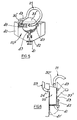
- FIGs 5 and 6 illustrate a further form of filtering and recepticle unit 20 ⁇ that can be used in place of the unit 20 in Figures 1 and 2 and which comprises an outer casing 40 whose base tapers downwards towards a central pivotting hatch 41 which is held closed by a fastener 42.
- the unit 20 ⁇ has an air inlet 24 ⁇ which extends through the hopper wall 12 and is connected with suction pipe 23 to provide a convenient provision of suction within the hopper.
- the outlet 30 ⁇ of unit 20 ⁇ is connected with pipe 21 and the blanking member 33 ⁇ which is of conical form and can be stored on the side of casing 40 within support brackets 43 when not held in use over the inlet 22.
- a filter 45 is provided within casing 44 to prevent the passage of seed, fertilizer or debris out through outlet 30 ⁇ to the fan.
- the unit 20 ⁇ can be emptied by disengaging fastener 42 from a slot in the hatch 41 and allowing the hatch to pivot downwards to its open position shown by dotted detail 41′ in Figure 6.
Landscapes
- Life Sciences & Earth Sciences (AREA)
- Soil Sciences (AREA)
- Environmental Sciences (AREA)
- Fertilizing (AREA)
Abstract
An agricultural seed drill or fertilizer spreader of the pneumatic type in which a fan (11) produces a flow of air to distribute seed and/or fertilizer to a plurality of dispensing units (7). The drill or spreader includes a vacuum cleaning system (20, 21, 23, 33) which employs the existing fan (11) to produce suction to remove unwanted seed or fertilizer from the drill or spreader. In one form of the invention the vacuum cleaning system includes an air suction pipe (21, 23) coupled to an air inlet (22) of the fan (11) via a blanking member (33) which extends over the inlet. The blanking member (33) may be held in position over the inlet by the suction action of the fan (11) or a support structure (32) may be provided which allows movement of the blanking members towards and away from the inlet (22). The vacuum cleaning system preferably includes a recepticle (20) for seed or fertilizer, the recepticle having an air inlet (24) connected with one portion (23) of the suction pipe and an air outlet (30) connected via another portion (21) of the auction pipe with the fan inlet (22). An air filter (28) is located within the recepticle between the recepticle inlet and outlet to prevent seed, fertilizer or debris being drawn through the recepticle into the fan (11).
Description
- This invention relates to agricultural drills and fertilizer spreaders of the pneumatic type that incorporate a fan to produce a flow of air in which to distribute seed and fertilizer.
- Agricultural drills and fertilizer spreaders need to be cleaned when changing the type of seed to be sown so as to avoid sowing mixed seed and also before storing the machine so as to avoid corrosion and seizing of the seed dispensing mechanisms. This task can be difficult and time consuming and is normally done on farm premises where special equipment and power supplies are available.
- It is an object of the present invention to provide a pneumatic drill or fertilizer spreader which mitigates the above difficulties.
- Thus according to the present invention there is provided a pneumatic drill or fertilizer spreader with a vacuum cleaning system that employs the existing fan to produce suction to remove unwanted seed and fertilizer from the drill or spreader.
- As will be appreciated, such a cleaning system can be readily incorporated into existing machines at low cost and would be permanently available for cleaning of the machines in any situation.
- The vacuum cleaning system may comprise an air suction pipe coupled to an air inlet of the fan. The air suction pipe may be coupled to the air inlet of the fan via a blanking member which extends over the inlet.
- The blanking member may be held in position over the inlet by the suction action of the fan or may be supported via a structure which allows movement of the blanking member towards and away from the fan inlet.
- The vacuum cleaning system may include an air filter to prevent seed, fertilizer or debris being drawn into the fan.
- The vacuum cleaning system a may also include a recepticle for seed or fertilizer, the recepticle having an air inlet connected with one portion of the suction pipe and an air outlet connected via another portion of the suction pipe with the fan inlet, the air filter being located within the recepticle between the recepticle inlet and outlet to prevent seed, fertilizer or debris being drawn through the recepticle into the fan.
- The invention will now be described by way of example with reference to the accompanying drawings in which:
- Figure 1 is a schematic side elevation of a pneumatic drill according to the invention,
- Figure 2 is a more detailed schematic diagram of the vacuum cleaning system in Figure 1,
- Figure 3 is a schematic diagram of an alternative blanking member arrangement for use in a vacuum cleaning system for use in a pneumatic drill,
- Figure 4 is a schematic diagram of an alternative filtering and recepticle unit, and
- Figures 5 and 6 are schematic diagrams showing side and end views of part of a still further form of filtering and recepticle unit.
- The illustrated drill comprises a frame 1 carrying a
seed hopper 2. A plurality ofseed metering mechanisms 3 dispense seed from the hopper into pneumatic distribution means 4 that conveys the seed in a flow of air to each of a plurality ofcoulters 5 pivotally mounted on the frame. Theseed metering mechanisms 3 are mounted in two rows across the width of the hopper, one beneath eachinclined bottom wall 6 of the hopper, and each delivers seed into the pneumatic distribution means comprising a venturi unit 7 and a length of tube 8 connecting the unit 7 to an associatedcoulter 5. The venturi units 7 are connected to acommon air manifold 9 that is pressurised via aduct 10 by afan 11 that is mounted on the forward facingwall 12 of thehopper 2. -
Tractor mounting points 13 are provided on the front of the frame 1 for connection of the drill to the rear lifting links of a trctor. A pair oflandwheels 14 are mounted on the frame so as to support the drill when it is lowered onto the ground for work, and atransmission system 15 between the landwheels and the metering mechanisms serves to drive the latter and dispense seed. - A
rotable control beam 16 is supported from the frame 1 and extends laterally across the width of the drill. Eachcoulter 5 comprises anarm 17 that is pivotally connected at its forward end to thebeam 16 and is pulled downwards into working engagement with the soil by atension spring 18 connected between thearm 17 andbeam 16. Anhydraulic ram 19 is connected between thebeam 16 and frame 1 and serves to rotate thebeam 16 to urge the coulters downwards into work, the sowing depth of the coulters being determined by the stroke of the ram. - A vacuum cleaning system in accordance with the present invention is mounted on the
front wall 12 of thehopper 2 and comprises an air filtering andseed recepticle unit 20 connected to thewall 12 andair suction pipes Suction pipe 21 connects anair outlet 30 of the filtering andrecepticle unit 20 with a screenedair inlet 22 of thefan 11,suction pipe 23 acts as a flexible cleaning hose connected to anair inlet 24 ofunit 20. - As shown in Figure 2, the filtering and
recepticle unit 20 comprise a closed housing having afloor 25 that slopes forwards and downwards away from thehopper wall 12, and a front door orhatch 26 that is hinged along itstop edge 27 and which opens forwards to allow any seed accumulated on thefloor 25 to fall out. Aremovable filter screen 28 is mounted vertically within theunit 20 to divide it internally into arear space 29 with theair outlet 30 in the top wall and aforward space 31 with theair inlet 24 in a side wall of the unit near the top. - Thus, air sucked into the unit via the
hose 23 passes through thescreen 28 and deposits any seed contained in the air in theforward space 31. As will be appreciated, the fall in velocity of the air on enteringunit 20 leads to the falling from suspension of any seed, fertilizer or debris which is drawn intounit 20 viahose 23.Filter screen 28 is thus an added safety arrangement to ensure that no seed, fertilizer or debris passes on into the fan. - The
suction pipe 21 comprises a flexible hose with one end connected to theair outlet 30 ofunit 20 and the other end connected to ablanking member 33. When the blanking member is positioned in its cleaning position over theair inlet 22, the suction effect of the fan as it draws air through theair inlet 22 causes the blanking member to seal over and around theinlet 22, thereby causing air to be drawn throughpipe 21, theunit 20 and thecleaning hose 23. Thehose 23 can therefore be used to remove seed or other loose material by suction from the hopper and mechanisms of the drill that need cleaning. - In a preferred arrangement the
blanking member 33 is manually located over theair inlet 22 or removed as required. Air suction alone may be sufficient to hold the blanking member in place, or some form of simple releasable fastening may be provided. The blanking member may cover all or only part of the air inlet depending on the suction characteristics of the fan and may be flexible and made of rubber or plastic material or rigid and made, for example, of metal. - In an alternative arrangement shown in Figure 3, a support structure in the form of a
metal pipe 32, which is connected withpipe 21, is welded or otherwise secured to the centre of thefan inlet 22 and theblanking member 33 is slidable towards and away from the inlet on thepipe 32 to give, for example, a working position of the blanking member shown in full lines when the blanking menber is over theinlet 22 and suction is applied topipe 21 and a non-working position shown in dotteddetail 33′ where the blanking member is spaced away from theinlet 22 and no suction is applied topipe 21. - Figure 4 illustrates an alternative form of filtering and
recepticle unit 20 that can be used in place of theunit 20 in Figures 1 and 2, and which comprises anouter casing 34 with anair inlet 24′ in its side wall near the top and aremovable lid 35 having afilter element 36 connected to it centrally and anair outlet 30′ that communicates with the container through thefilter element 36. Seed filtered from the air as it is sucked through thecontainer 20′ collects on thefilter 36 and in the bottom of the container and is removed periodically by opening the lid and emptying the container. - Figures 5 and 6 illustrate a further form of filtering and
recepticle unit 20˝ that can be used in place of theunit 20 in Figures 1 and 2 and which comprises anouter casing 40 whose base tapers downwards towards acentral pivotting hatch 41 which is held closed by afastener 42. Theunit 20˝ has anair inlet 24˝ which extends through thehopper wall 12 and is connected withsuction pipe 23 to provide a convenient provision of suction within the hopper. Theoutlet 30˝ ofunit 20˝ is connected withpipe 21 and theblanking member 33˝ which is of conical form and can be stored on the side ofcasing 40 withinsupport brackets 43 when not held in use over theinlet 22. Afilter 45 is provided within casing 44 to prevent the passage of seed, fertilizer or debris out throughoutlet 30˝ to the fan. - As will be appreciated, the
unit 20˝ can be emptied by disengagingfastener 42 from a slot in thehatch 41 and allowing the hatch to pivot downwards to its open position shown by dotteddetail 41′ in Figure 6.
Claims (10)
1) An agricultural seed drill or fertilizer spreader of the pneumatic type in which a fan (11) produces a flow of air to distribute seed and/or fertilizer to a plurality of dispensing units (7), the drill or spreader being characterised by the provision of a vacuum cleaning system (20, 21, 23, 33) which employs the fan (11) to produce suction to remove unwanted seed or fertilizer from the drill or spreader.
2) A drill or spreader according to Claim 1 characterised in that the vacuum cleaning system (20, 21, 23, 33) comprises an air suction pipe (21, 23) coupled to an air inlet (22) of the fan (11).
3) A drill or spreader according to Claim 2 characterised in that the air suction pipe (21, 23) is coupled to the air inlet (22) of the fan (11) via a blanking member (33) which extends over the inlet.
4) A drill or spreader according to Claim 3 characterised in that the blanking member (33) is held in position over the inlet by the suction action of the fan (11).
5) A drill or spreader according to Claim 3 characterised in that the blanking member (33) is supported via a support structure (32) which allows movement of the blanking member between a position over the inlet (22) in which suction is applied to the vacumn cleaning system (20, 21, 23, 33) and a position away from the inlet in which no suction is applied to the vacumn cleaning system.
6) A drill or spreader according to any one of Claims 1 to 5 characterised by the inclusion in the vacuum cleaning system (20, 21, 23, 33) of an air filter (28) to prevent seed, fertilizer or debris being drawn into the fan (11).
7) A drill or spreader according to Claim 6 characterised in that the vacuum cleaning system ((20, 21, 23, 33) includes a recepticle (20) for seed or fertilizer, the recepticle having an air inlet (24) connected with one portion (23) of the suction pipe and an air outlet (30) connected via another portion (21) of the suction pipe with the fan inlet (22), the air filter (28) being located within the recepticle between the recepticle inlet and outlet to prevent seed, fertilizer or debris being drawn through the recepticle into the fan (11).
8) A drill or spreader according to Claim 7 characterised in that the recepticle (20 : 20˝) includes a pivotable hatch (26 : 41) through which the recepticle can be emptied.
9) A drill or spreader according to Claim 8 characterised in that the base (25) of the recepticle (20) slopes to assist discharge of seed a fertilizer through the hatch (26).
10) A drill or spreader according to Claims 7, 8 or 9 characterised in that the recepticle (20˝) carries a support means (43) for storage of the blanking member (33˝) when not in use.
Applications Claiming Priority (2)
| Application Number | Priority Date | Filing Date | Title |
|---|---|---|---|
| GB888804660A GB8804660D0 (en) | 1988-02-27 | 1988-02-27 | Pneumatic drills & fertilizer spreaders |
| GB8804660 | 1988-02-27 |
Publications (1)
| Publication Number | Publication Date |
|---|---|
| EP0331302A1 true EP0331302A1 (en) | 1989-09-06 |
Family
ID=10632522
Family Applications (1)
| Application Number | Title | Priority Date | Filing Date |
|---|---|---|---|
| EP89301321A Withdrawn EP0331302A1 (en) | 1988-02-27 | 1989-02-13 | Pneumatic drills and fertilizer spreaders |
Country Status (2)
| Country | Link |
|---|---|
| EP (1) | EP0331302A1 (en) |
| GB (2) | GB8804660D0 (en) |
Cited By (13)
| Publication number | Priority date | Publication date | Assignee | Title |
|---|---|---|---|---|
| US7640877B1 (en) | 2008-11-14 | 2010-01-05 | Cnh Canada, Ltd. | Dense phase distribution branch |
| US7743719B2 (en) | 2008-11-14 | 2010-06-29 | Cnh Canada, Ltd. | Sectional distribution of granular product |
| US7752984B2 (en) | 2008-11-14 | 2010-07-13 | Cnh Canada, Ltd. | Device and method for dense phase transport of seed |
| US7779769B2 (en) | 2008-11-14 | 2010-08-24 | Cnh Canada, Ltd. | Agricultural implement with dense phase product flow from a primary container |
| US7789103B2 (en) | 2008-11-14 | 2010-09-07 | Cnh Canada, Ltd. | Dense phase induction system and method |
| US7798078B2 (en) | 2008-11-14 | 2010-09-21 | Cnh Canada, Ltd. | Granular containment assembly and method |
| US7798079B2 (en) | 2008-11-14 | 2010-09-21 | Cnh Canada, Ltd. | Pressure supply assembly for an agricultural implement with dense phase product flow |
| US7806061B2 (en) | 2008-11-14 | 2010-10-05 | Cnh Canada, Ltd. | Agricultural implement with dense phase product dispensing and purging |
| CN101653059B (en) * | 2008-08-19 | 2012-06-06 | 刘忠义 | Pneumatic side deep fertilization cultivator |
| US8342373B2 (en) | 2008-11-14 | 2013-01-01 | Cnh Canada, Ltd. | Valve and method for dense phase flow control |
| CN105409413A (en) * | 2015-10-29 | 2016-03-23 | 四川天本生物技术有限公司 | Air-flow type deep-plowing and deep-fertilizing system |
| US9546051B2 (en) | 2013-12-17 | 2017-01-17 | Cnh Industrial Canada, Ltd. | System for increasing throughput of an agricultural product metering system |
| WO2021089449A1 (en) * | 2019-11-08 | 2021-05-14 | Amazonen-Werke H. Dreyer Gmbh & Co. Kg | Separating device for pneumatically feeding granular material, and filter cartridge for use in the separating device |
Families Citing this family (1)
| Publication number | Priority date | Publication date | Assignee | Title |
|---|---|---|---|---|
| RU208808U1 (en) * | 2021-06-16 | 2022-01-14 | Федеральное государственное бюджетное образовательное Учреждение высшего образования "Воронежский государственный аграрный университет имени императора Петра 1" (ФГБОУ ВО Воронежский ГАУ) | Pneumatic seed drill |
Citations (3)
| Publication number | Priority date | Publication date | Assignee | Title |
|---|---|---|---|---|
| EP0050829A1 (en) * | 1980-10-29 | 1982-05-05 | Institut Technique Des Cereales Et Des Fourrages | Planter unit for experimental plots |
| EP0100723A1 (en) * | 1982-07-29 | 1984-02-15 | LACAILLE S.A., Société Anonyme dite: | Multi-purpose seed drill |
| EP0150833A2 (en) * | 1984-02-02 | 1985-08-07 | Amazonen-Werke H. Dreyer GmbH & Co. KG | Machine for a dosed distribution of granules |
-
1988
- 1988-02-27 GB GB888804660A patent/GB8804660D0/en active Pending
-
1989
- 1989-02-13 EP EP89301321A patent/EP0331302A1/en not_active Withdrawn
- 1989-02-13 GB GB8903228A patent/GB2215969A/en not_active Withdrawn
Patent Citations (3)
| Publication number | Priority date | Publication date | Assignee | Title |
|---|---|---|---|---|
| EP0050829A1 (en) * | 1980-10-29 | 1982-05-05 | Institut Technique Des Cereales Et Des Fourrages | Planter unit for experimental plots |
| EP0100723A1 (en) * | 1982-07-29 | 1984-02-15 | LACAILLE S.A., Société Anonyme dite: | Multi-purpose seed drill |
| EP0150833A2 (en) * | 1984-02-02 | 1985-08-07 | Amazonen-Werke H. Dreyer GmbH & Co. KG | Machine for a dosed distribution of granules |
Cited By (14)
| Publication number | Priority date | Publication date | Assignee | Title |
|---|---|---|---|---|
| CN101653059B (en) * | 2008-08-19 | 2012-06-06 | 刘忠义 | Pneumatic side deep fertilization cultivator |
| US7798079B2 (en) | 2008-11-14 | 2010-09-21 | Cnh Canada, Ltd. | Pressure supply assembly for an agricultural implement with dense phase product flow |
| US7752984B2 (en) | 2008-11-14 | 2010-07-13 | Cnh Canada, Ltd. | Device and method for dense phase transport of seed |
| US7779769B2 (en) | 2008-11-14 | 2010-08-24 | Cnh Canada, Ltd. | Agricultural implement with dense phase product flow from a primary container |
| US7789103B2 (en) | 2008-11-14 | 2010-09-07 | Cnh Canada, Ltd. | Dense phase induction system and method |
| US7798078B2 (en) | 2008-11-14 | 2010-09-21 | Cnh Canada, Ltd. | Granular containment assembly and method |
| US7640877B1 (en) | 2008-11-14 | 2010-01-05 | Cnh Canada, Ltd. | Dense phase distribution branch |
| US7806061B2 (en) | 2008-11-14 | 2010-10-05 | Cnh Canada, Ltd. | Agricultural implement with dense phase product dispensing and purging |
| US7743719B2 (en) | 2008-11-14 | 2010-06-29 | Cnh Canada, Ltd. | Sectional distribution of granular product |
| US8342373B2 (en) | 2008-11-14 | 2013-01-01 | Cnh Canada, Ltd. | Valve and method for dense phase flow control |
| US9546051B2 (en) | 2013-12-17 | 2017-01-17 | Cnh Industrial Canada, Ltd. | System for increasing throughput of an agricultural product metering system |
| CN105409413A (en) * | 2015-10-29 | 2016-03-23 | 四川天本生物技术有限公司 | Air-flow type deep-plowing and deep-fertilizing system |
| CN105409413B (en) * | 2015-10-29 | 2018-04-03 | 四川天本生物技术有限公司 | Air-flowing type subsoiling deep placement system |
| WO2021089449A1 (en) * | 2019-11-08 | 2021-05-14 | Amazonen-Werke H. Dreyer Gmbh & Co. Kg | Separating device for pneumatically feeding granular material, and filter cartridge for use in the separating device |
Also Published As
| Publication number | Publication date |
|---|---|
| GB8903228D0 (en) | 1989-03-30 |
| GB2215969A (en) | 1989-10-04 |
| GB8804660D0 (en) | 1988-03-30 |
Similar Documents
| Publication | Publication Date | Title |
|---|---|---|
| US4296695A (en) | Seeding device with air distribution system | |
| GB2215969A (en) | Pneumatic drills and fertilizer spreaders | |
| US2872883A (en) | Planter runner guard | |
| DE69915210T2 (en) | Storage and collection containers in pneumatic seed drills | |
| US5271567A (en) | Fertilizer distribution head and dispensing chute | |
| US8191202B2 (en) | Mobile vacuum apparatus for collection of liquid or semi-liquid materials | |
| US3860146A (en) | Seed dispensing mechanism | |
| CA1053984A (en) | Liquid manure system | |
| US4047368A (en) | Attachment for collecting mower discharge in a plurality of bags | |
| US5575225A (en) | Air-powered apparatus for filling grain drills and method of using same | |
| US4796322A (en) | Rear dumping lawn sweeper with folding wind apron | |
| US3813725A (en) | Vacuum cleaner construction | |
| US6347593B1 (en) | Modular dethatcher and seeder | |
| US20090293911A1 (en) | Collection means for a mobile vacuum apparatus for the collection of liquid or semi-liquid materials | |
| US6971324B1 (en) | Bulk seed handling and dispensing system | |
| US4142351A (en) | Mower discharge boot | |
| CN210995229U (en) | Agricultural product is planted with device of dressing a seed | |
| CA1069706A (en) | Grass collection bag for rotary lawn mowers | |
| JP2013022002A (en) | Working machine equipped with fertilizer spreader | |
| US5457946A (en) | Grass catching attachment for rotary lawn mowers | |
| US4259832A (en) | Grass collection apparatus | |
| US6516975B2 (en) | Cottonseed feeder | |
| GB2251166A (en) | Slurry spreaders | |
| US20050277454A1 (en) | Device and method for collecting chaff | |
| US4791779A (en) | Leaf-bagger |
Legal Events
| Date | Code | Title | Description |
|---|---|---|---|
| PUAI | Public reference made under article 153(3) epc to a published international application that has entered the european phase |
Free format text: ORIGINAL CODE: 0009012 |
|
| AK | Designated contracting states |
Kind code of ref document: A1 Designated state(s): DE ES FR GB IT NL |
|
| STAA | Information on the status of an ep patent application or granted ep patent |
Free format text: STATUS: THE APPLICATION IS DEEMED TO BE WITHDRAWN |
|
| 18D | Application deemed to be withdrawn |
Effective date: 19900307 |